Note : Les descriptions sont présentées dans la langue officielle dans laquelle elles ont été soumises.
DEMANDE OU BREVET VOLUMINEUX
LA PRESENTE PARTIE DE CETTE DEMANDE OU CE BREVET COMPREND
PLUS D'UN TOME.
CECI EST LE TOME 1 DE 3
CONTENANT LES PAGES 1 A 170
NOTE : Pour les tomes additionels, veuillez contacter le Bureau canadien des
brevets
JUMBO APPLICATIONS/PATENTS
THIS SECTION OF THE APPLICATION/PATENT CONTAINS MORE THAN ONE
VOLUME
THIS IS VOLUME 1 OF 3
CONTAINING PAGES 1 TO 170
NOTE: For additional volumes, please contact the Canadian Patent Office
NOM DU FICHIER / FILE NAME:
NOTE POUR LE TOME / VOLUME NOTE:
CA 02948640 2016-11-09
WO 2015/184252
PCT/US2015/033165
ELECTRICAL POWER GENERATION SYSTEMS AND METHODS
REGARDING SAME
CROSS-REFERENCES OF RELATED APPLICATIONS
This application claims the benefit of U.S. Provisional Application Nos.
62/004,883, filed
May 29, 2014; 62/012,193, filed June 13, 2014; 62/016,540, filed June 24,
2014; 62/021,699,
filed July 7, 2014; 62/023,586, filed July 11, 201.4; 62/026,698, filed July
20, 2014; 621037,152,
filed August 14, 2014; 62/041,026, filed August 22, 2014; 62/058,844, filed
October 2, 2014;
62/068,592, filed October 24, 2014; 62/083,029, filed November 24, 2014;
62/087,234, filed
December 4, 2014; 62/092,230, filed December 15, 2014; 62/113,211, filed
February 6, 2015;
62/141,079, filed March 31, 2015; 62/149,501, filed April 17, 2015;
62/1.59,230, filed May 9,
2015 and 62/1.65,340, filed May 22, 2015, all of which are incorporated herein
by reference,
The present disclosure relates to the field of power generation and, in
particular, to
systems, devices, and methods for the generation of power. More specifically,
embodiments of
the present disclosure are directed to power generation devices and systems,
as well as related
methods, which produce optical power, plasma, and thermal power and produces
electrical
power via an optical to electric power converter, plasma to electric power
converter, photon to
electric power converter, or a thermal to electric power converter. In
addition, embodiments of
the present disclosure describe systems, devices, and methods that use the
ignition of a water or
water-based fuel source to generate optical power, mechanical power,
electrical power, and/or
thermal power using photovoltaic power converters. These and other related
embodiments are
described in detail in the present disclosure.
Power generation can take many forms, harnessing the power from plasma.
Successful
commercialization of plasma may depend on power generation systems capable of
efficiently
forming plasma and then capturing the power of the plasma produced.
Plasma may be formed during ignition of certain fuels. These fuels can include
water or
water-based fuel source. During ignition, a plasma cloud of electron-stripped
atoms is formed,
and high optical power may be released. The high optical power of the plasma
can be harnessed
by an electric converter of the present disclosure. The ions and excited state
atoms can
recombine and undergo electronic relaxation to emit optical power. The optical
power can be
converted to electricity with photovoltaics.
Certain embodiments of the present disclosure are directed to a power
generation system
comprising: a plurality of electrodes configured to deliver power to a fuel to
ignite the fuel and
produce a plasma; a source of electrical power configured to deliver
electrical energy to the
plurality of electrodes; and at least one photovoltaic power converter
positioned to receive at
least a plurality of plasma photons.
SUBSTITUTE SHEET (RULE 26)
CA 02948640 2016-11-09
WO 2015/184252
PCT/US2015/033165
In one embodiment, the present disclosure is directed to a power system that
generates at
least one of electrical energy and thermal energy comprising:
at least one vessel capable of a pressure of below atmospheric;
shot comprising reactants, the reactants comprising;
a) at least one source of catalyst or a catalyst comprising nascent H20;
b) at least one source of 1120 or H20;
c) at least one source of atomic hydrogen or atomic hydrogen; and
d) at least one of a conductor and a conductive matrix;
at least one shot injection system comprising at least one augmented railgun,
wherein the
augmented railgun comprises separated electrified rails and magnets that
produce a
magnetic field perpendicular to the plane of the rails, and the circuit
between the rails is
open until closed by the contact of the shot with the rails;
at least one ignition system to cause the shot to form at least one of light-
emitting plasma and
thermal-emitting plasma, at least one ignition system comprising:
a) at least one set of electrodes to confine the. shot; and
b) a source of electrical power to deliver a short burst of high-current
electrical energy;
wherein the at least one set of electrodes form an open circuit, wherein the
open circuit is
closed by the injection of the shot to cause the high current to flow to
achieve ignition,
and the source of electrical power to deliver a short burst of high-current
electrical energy
comprises at least one of the following:
a voltage selected to cause a high AC, DC, or an AC-DC mixture of current that
is
in the range of at least one of 100 A to 1,000,000 A, 1 kA to 100,000 A, 10 kA
to 50 kA;
a DC or peak AC current density in the range of at least one of 100 A/cm2to
1,000,000 A/cm2, 1000 A/cm2 to 1.00,000 A/cm2, and 2000 A/cm2 to 50,000 A/cm2;
the voltage is determined by the conductivity of the solid fuel or energetic
material wherein the voltage is given by the desired current times the
resistance of the
solid fuel or energetic material sample;
the DC or peak AC voltage is in the range of at least one of 0.1 V to 500 kV,
0.1
V to 100 kV, and 1 V to 50 kV., and
the AC frequency is in range of at least one of 0.1 112 to 10 Gliz, 1 Hz to 1
MHz, 10 Hz
to 100 kHz, and 100 Hz to 10 kHz.
a system to recover reaction products of the reactants comprising at least one
of gravity and
an augmented plasma railgun recovery system comprising at least one magnet
providing
a magnetic field and a vector-crossed current component of the ignition
electrodes;
2
SUBSTITUTE SHEET (RULE 26)
CA 02948640 2016-11-09
WO 2015/184252
PCT/US2015/033165
at least one regeneration system to regenerate additional reactants from the.
reaction products
and form additional shot comprising a pelletizer comprising a smelter to form
molten
reactants, a system to add H2 and H20 to the molten reactants, a melt dripper,
and a water
reservoir to form shot,
wherein the additional reactants comprise:
a) at least one source of catalyst or a catalyst comprising nascent H20;
b) at least one source of 120 or F20;
c) at least one source of atomic hydrogen or atomic hydrogen; and
d) at least one of a conductor and a conductive matrix; and
at least one power converter or output system of at least one of the light and
thermal output to
electrical power and/or thermal power comprising at least one or more of the
group of a
photovoltaic converter, a photoelectronic converter, a plasmadynamic
converter, a
therrnionic converter, a thermoelectric converter, a Sterling engine, a
Brayton cycle
engine, a Rankine cycle engine, and a heat engine, and a heater.
In another embodiment, the present disclosure is directed to a power system
that
generates at least one of electrical energy and thermal energy comprising:
at least one vessel capable of a pressure of below atmospheric;
shot comprising reactants, the reactants comprising at least one of silver,
copper, absorbed
hydrogen, and water;
at least one shot injection system comprising at least one augmented railgun
wherein the
augmented railgun comprises separated electrified rails and magnets that
produce a
magnetic field perpendicular to the plane of the rails, and the circuit
between the rails is
open until closed by the contact of the shot with the rails;
at least one ignition system to cause the shot to form at least one of light-
emitting plasma and
thermal-emitting plasma, at least one ignition system comprising:
a) at least one set of electrodes to confine the shot; and
b) a source of electrical power to deliver a short burst of high-current
electrical energy;
wherein the at least one set of electrodes that are separated to form an open
circuit,
wherein the open circuit is closed by the injection of the shot to cause the
high current to
flow to achieve ignition, and he source of electrical power to deliver a short
burst of high-
current electrical energy comprises at least one of the following:
a voltage selected to cause a high AC, DC, or an AC-DC mixture of current that
is
in the range of at least one of 100 A to .1,000,000 A, 1 kA to 100,000 A, 10
kA to SO kA;
3
SUBSTITUTE SHEET (RULE 26)
CA 02948640 2016-11-09
WO 2015/184252
PCT/US2015/033165
a DC or peak AC current density in the range of at least one of 100 A/cm2 to
1,000,000 A/cm2, 1000 A/cm2 to 100,000 A/cm2, and 2000 A/cm2 to 50,000 A/cm2;
the voltage is determined by the conductivity of the solid fuel or energetic
material wherein the voltage is given by the desired current times the
resistance of the
solid fuel or energetic material sample;
the DC or peak AC voltage is in the range of at least one of 0.1 V to 500 kV,
0.1
V to 100 kV, and 1 V to 50 kV, and
the AC frequency is in range of at least one of 0.1 Hz to 10 GHz, 1. Hz to 1
MHz, 10 Hz
to 100 kHz, and 100 Hz to 10 kHz.
a system to recover reaction products of the reactants comprising at least one
of gravity and a
augmented plasma railgun recovery system comprising at least one magnet
providing a
magnetic field and a vector-crossed current component of the ignition
electrodes;
at least one regeneration system to regenerate additional reactants from the
reaction products
and form additional shot comprising a pelletizer comprising a smelter to form
molten
reactants, a system to add H2 and 1120 to the molten reactants, a melt
dripper, and a water
reservoir to form shot,
wherein the additional reactants comprise at least one of silver, copper,
absorbed
hydrogen, and water;
at least one power converter or output system comprising a concentrator
ultraviolet
photovoltaic converter wherein the photovoltaic cells comprise at least one
compound
chosen from a Group III nitride, CiaAIN, GaN, and InGaN.
In another embodiment, the present disclosure is directed to a power system
that
generates at least one of electrical energy and thermal energy comprising:
at least one vessel;
shot comprising reactants, the reactants comprising:
e) at least one source of catalyst or a catalyst comprising nascent H20;
t) at least one source of H20 or H20;
g) at least one source of atomic hydrogen or atomic hydrogen; and
h) at least one of a conductor and a conductive matrix;
at least one shot injection system;
at least one shot ignition system to cause the shot to form at least one of
light-emitting
plasma and thermal-emitting plasma;
a system to recover reaction products of the reactants;
at least one regeneration system to regenerate additional reactants from the
reaction products
and form additional shot,
4
SUBSTITUTE SHEET (RULE 26)
CA 02948640 2016-11-09
WO 2015/184252
PCT/US2015/033165
wherein the additional reactants comprise:
e) at least one source of catalyst or a catalyst comprising nascent H20;
f) at least one source of 1-120 or H20;
g) at least one source of atomic hydrogen or atomic hydrogen; and
h) at least one of a conductor and a conductive matrix; and
at least one power converter or output system of at least one of the light and
thermal
output to electrical power and/or thermal power.
In another embodiment, the present disclosure is directed to a power system
that
generates at least one of electrical energy and thermal energy comprising:
at least one vessel;
slurry comprising reactants, the reactants comprising;
a) at least one source of catalyst or a catalyst comprising nascent 1-120;
b) at least one source of H20 or H20;
c) at least one source of atomic hydrogen or atomic hydrogen; and
d) at least one of a conductor and a conductive matrix;
at least one slurry injection system comprising rotating roller electrodes
comprising a rotary
slurry pump;
at least one slurry ignition system to cause the shot to form light-emitting
plasma;
a system to recover reaction products of the reactants;
at least one regeneration system to regenerate additional reactants from the
reaction products
and form additional slurry,
wherein the additional reactants comprise:
a) at least one source of catalyst or a catalyst comprising nascent H20;
b) at least one source of H20 or H/0;
c) at least one source of atomic hydrogen or atomic hydrogen; and
d) at least one of a conductor and a conductive matrix; and
at least one power converter or output system of at least one of the light and
thermal
output to electrical power and/or thermal power.
Certain embodiments of the present disclosure are directed to a power
generation system
comprising: a plurality of electrodes configured to deliver power to a fuel to
ignite the fuel and
produce a plasma; a source of electrical power configured to deliver
electrical energy to the
plurality of electrodes; and at least one photovoltaic power converter
positioned to receive at
least a plurality of plasma photons.
In one embodiment, the present disclosure is directed to a power system that
generates at
least one of direct electrical energy and thermal energy comprising:
SUBSTITUTE SHEET (RULE 26)
CA 02948640 2016-11-09
WO 2015/184252
PCT/US2015/033165
at least one vessel;
reactants comprising:
a) at least one source of catalyst or a catalyst comprising nascent H20,
b) at least one source of atomic hydrogen or atomic hydrogen;
c) at least one of a conductor and a conductive matrix; and
at least one set of electrodes to confine the hydrino reactants,
a source of electrical power to deliver a short burst of high-current
electrical energy;
a reloading system;
at least one system to regenerate the initial reactants from the reaction
products, and
at least one plasma dynamic converter or at least one photovoltaic converter.
In one exemplary embodiment, a method of producing electrical power may
comprise
supplying a fuel to a region between a plurality of electrodes; energizing the
plurality of
electrodes to ignite the fuel to form a plasma; converting a plurality of
plasma photons into
electrical power with a photovoltaic power converter; and outputting at least
a portion of the
electrical power.
In another exemplary embodiment, a method of producing electrical power may
comprise
supplying a fuel to a region between a plurality of electrodes; energizing the
plurality of
electrodes to ignite the fuel to form a plasma; converting a plurality of
plasma photons into
thermal power with a photovoltaic power converter; and outputting at least a
portion of the
electrical power.
In an embodiment of the present disclosure, a method of generating power may
comprise
delivering an amount of fuel to a fuel loading region, wherein the fuel
loading region is located
among a plurality of electrodes; igniting the fuel by flowing a current of at
least about 2,000
A/cm2 through the fuel by applying the current to the plurality of electrodes
to produce at least
one of plasma, light, and heat; receiving at least a portion of the light in a
photovoltaic power
converter; converting the light to a different form of power using the
photovoltaic power
converter; and outputting the different form of power.
In an additional embodiment, the present disclosure is directed to a water arc
plasma
power system comprising: at least one closed reaction vessel; reactants
comprising at least one of
source of H20 and 1120; at least one set of electrodes; a source of electrical
power to deliver an
initial high breakdown voltage of the 1120 and provide a subsequent high
current, and a heat
exchanger system, wherein the power system generates arc plasma, light, and
thermal energy,
and at least one photovoltaic power converter.
Certain embodiments of the. present disclosure are directed to a power
generation system
comprising: an electrical power source of at least about 2,000 Alcm2 or of at
least about 5,000
6
SUBSTITUTE SHEET (RULE 26)
CA 02948640 2016-11-09
WO 2015/184252
PCT/US2015/033165
kW; a plurality of electrodes electrically coupled to the electrical power
source; a fuel loading
region configured to receive a solid fuel, wherein the plurality of electrodes
is configured to
deliver electrical power to the solid fuel to produce a plasma; and at least
one of a plasma power
converter, a photovoltaic power converter, and thermal to electric power
converter positioned to
receive at least a portion of the plasma, photons, and/or heat generated by
the reaction. Other
embodiments are directed to a power generation system, comprising: a plurality
of electrodes; a
fuel loading region located between the plurality of electrodes and configured
to receive a
conductive fuel, wherein the plurality of electrodes are configured to apply a
current to the
conductive fuel sufficient to ignite the conductive fuel and generate at least
one of plasma and
thermal power; a delivery mechanism for moving the conductive fuel into the
fuel loading
region; and at least one of a photovoltaic power converter to convert the
plasma photons into a
form of power, or a thermal to electric converter to convert the thermal power
into a nontherrnal
form of power comprising electricity or mechanical power. Further embodiments
are directed to
a method of generating power, comprising: delivering an amount of fuel to a
fuel loading region,
wherein the fuel loading region is located among a plurality of electrodes;
igniting the fuel by
flowing a current of at least about 2,000 .A/cm2 through the fuel by applying
the current to the
plurality of electrodes to produce at least one of plasma, light, and heat;
receiving at least a
portion of the light in a photovoltaic power converter; converting the light
to a different form of
power using the photovoltaic power converter; and outputting the different
form of power.
Additional embodiments are directed to a power generation system, comprising:
an
electrical power source of at least about 5,000 kW; a plurality of spaced
apart electrodes,
wherein the plurality of electrodes at least partially surround a fuel, are
electrically connected to
the electrical power source, are configured to receive a current to ignite the
fuel, and at least one
of the plurality of electrodes is moveable; a delivery mechanism for moving
the fuel; and a
photovoltaic power converter configured to convert plasma generated from the
ignition of the
fuel into a non-plasma form of power. Additionally provided in the present
disclosure is a power
generation system, comprising: an electrical power source of at least about
2,000 Alcm2; a
plurality of spaced apart electrodes, wherein the plurality of electrodes at
least partially surround
a fuel, are electrically connected to the electrical power source, are
configured to receive a
current to ignite the fuel, and at least one of the plurality of electrodes is
moveable; a delivery
mechanism for moving the fuel; and a photovoltaic power converter configured
to convert
plasma generated from the ignition of the fuel into a non-plasma form of
power.
Another embodiments is directed to a power generation system, comprising: an
electrical
power source of at least about 5,000 kW or of at least about 2,000 A/cm2; a
plurality of spaced
apart electrodes, wherein at least one of the plurality of electrodes includes
a compression
7
SUBSTITUTE SHEET (RULE 26)
CA 02948640 2016-11-09
WO 2015/184252
PCT/US2015/033165
mechanism; a fuel loading region configured to receive a fuel, wherein the
fuel loading region is
surrounded by the plurality of electrodes so that the compression mechanism of
the at least one
electrode is oriented towards the fuel loading region, and wherein the
plurality of electrodes are
electrically connected to the electrical power source and configured to supply
power to the fuel
received in the fuel loading region to ignite the fuel; a delivery mechanism
for moving the fuel
into the fuel loading region; and a photovoltaic power converter configured to
convert photons
generated from the ignition of the fuel into a non-photon form of power. Other
embodiments of
the present disclosure are directed to a power generation system, comprising.
an electrical power
source of at least about 2,000 A/cm2; a plurality of spaced apart electrodes,
wherein at least one
of the plurality of electrodes includes a compression mechanism; a fuel
loading region
configured to receive a fuel, wherein the fuel loading region is surrounded by
the plurality of
electrodes so that the compression mechanism of the at least one electrode is
oriented towards
the. fuel loading region; and wherein the plurality of electrodes are
electrically connected to the
electrical power source and configured to supply power to the fuel received in
the fuel loading
region to ignite the fuel; a delivery mechanism for moving the fuel into the
fuel loading region;
and a plasma power converter configured to convert plasma generated from the
ignition of the
fuel into a non-plasma form of power.
Embodiments of the present disclosure are also directed to power generation
system,
comprising: a plurality of electrodes; a fuel loading region surrounded by the
plurality of
electrodes and configured to receive a fuel, wherein the plurality of
electrodes is configured to
ignite the fuel located in the fuel loading region; a delivery mechanism for
moving the fuel into
the fuel loading region; a photovoltaic power converter configured to convert
photons generated
from the ignition of the fuel into a non-photon form of power; a removal
system for removing a
byproduct of the ignited fuel; and a regeneration system operably coupled to
the removal system
for recycling the removed byproduct of the ignited fuel into recycled fuel.
Certain embodiments
of the present disclosure are also directed to a power generation system,
comprising: an electrical
power source configured to output a current of at least about 2,000 A/cm2 or
of at least about
5,000 kW; a plurality of spaced apart electrodes electrically connected to the
electrical power
source; a fuel loading region configured to receive a fuel, wherein the fuel
loading region is
surrounded by the plurality of electrodes, and wherein the plurality of
electrodes is configured to
supply power to the fuel to ignite the fuel when received in the fuel loading
region; a delivery
mechanism for moving the fuel into the fuel loading region; and a photovoltaic
power converter
configured to convert a plurality of photons generated from the ignition of
the fuel into a non-
photon form of power. Certain embodiments may further include one or more of
output power
terminals operably coupled to the photovoltaic power converter; a power
storage device; a sensor
8
SUBSTITUTE SHEET (RULE 26)
CA 02948640 2016-11-09
WO 2015/184252
PCT/US2015/033165
configured to measure at least one parameter associated with the power
generation system; and a
controller configured to control at least a process associated with the power
generation system.
Certain embodiments of the present disclosure are also directed to a power
generation system,
comprising: an electrical power source configured to output a current of at
least about 2,000
A/cm2 or of at least about 5,000 kW; a plurality of spaced apart electrodes,
wherein the plurality
of electrodes at least partially surround a fuel, are electrically connected
to the electrical power
source, are configured to receive a current to ignite the fuel, and at least
one of the plurality of
electrodes is moveable; a delivery mechanism for moving the fuel; and a
photovoltaic power
converter configured to convert photons generated from the ignition of the
fuel into a different
form of power:
Additional embodiments of the present disclosure are directed to a power
generation
system, comprising: an electrical power source of at least about 5,000 kW or
of at least about
2,000 A/cm2; a plurality of spaced apart electrodes electrically connected to
the electrical power
source; a fuel loading region configured to receive a fuel, wherein the fuel
loading region is
surrounded by the plurality of electrodes, and wherein the plurality of
electrodes is configured to
supply power to the fuel to ignite the fuel when received in the fuel loading
region; a delivery
mechanism for moving the fuel into the fuel loading region; a photovoltaic
power converter
configured to convert a plurality of photons generated from the ignition of
the fuel into a non-
photon form of power; a sensor configured to measure at least one parameter
associated with the
power generation system; and a controller configured to control at least a
process associated with
the power generation system. Further embodiments are directed to a power
generation system,
comprising: an electrical power source of at least about 2;000 iVern2; a
plurality of spaced apart
electrodes electrically connected to the electrical power source; a fuel
loading region configured
to receive a fuel, wherein the fuel loading region is surrounded by the
plurality of electrodes, and
wherein the plurality of electrodes is configured to supply power to the fuel
to ignite the fuel
when received in the fuel loading region; a delivery mechanism for moving the
fuel into the fuel
loading region; a plasma power converter configured to convert plasma
generated from the
ignition of the fuel into a non-plasma form of power; a sensor configured to
measure at least one
parameter associated with the power generation system; and a controller
configured to control at
least a process associated with the power generation system.
Certain embodiments of the present disclosure are directed to a power
generation system,
comprising: an electrical power source of at least about 5,000 kW or of at
least about 2,000
A/cm2; a plurality of spaced apart electrodes electrically connected to the
electrical power
source; a fuel loading region configured to receive a fuel, wherein the fuel
loading region is
surrounded by the plurality of electrodes, and wherein the plurality of
electrodes is configured to
9
SUBSTITUTE SHEET (RULE 26)
CA 02948640 2016-11-09
WO 2015/184252
PCT/US2015/033165
supply power to the fuel to ignite the fuel when received in the fuel loading
region, and wherein
a pressure in the fuel loading region is a partial vacuum; a delivery
mechanism for moving the
fuel into the fuel loading region; and a photovoltaic power converter
configured to convert
plasma generated from the ignition of the fuel into a non-plasma form of
power. Some
embodiments may include one or more of the following additional features: the
photovoltaic
power converter may be located within a vacuum cell; the photovoltaic power
converter may
include at least one of an antireflection coating, an optical impedance
matching coating, or a
protective coating; the photovoltaic power converter may be operably coupled
to a cleaning
system configured to clean at least a portion of the photovoltaic power
converter; the power
generation system may include an optical filter; the photovoltaic power
converter may comprise
at least one of a monocrystalline cell, a polycrystalline cell, an amorphous
cell, a string/ribbon
silicon cell, a multi-junction cell, a homojunction cell, a heterojunction
cell, a p-i-n device, a
thin-film cell, a dye-sensitized cell, and an organic photovoltaic cell; and
the photovoltaic power
converter may comprise at multi-junction cell, wherein the multi-junction cell
comprises at least
one of an inverted cell, an upright cell, a lattice-mismatched cell, a lattice-
matched cell, and a
cell comprising Group MA' semiconductor materials.
Additional exemplary embodiments are directed to a system configured to
produce
power, comprising; a fuel supply configured to supply a fuel; a power supply
configured to
supply an electrical power; and at least one gear configured to receive the
fuel and the electrical
power, wherein the at least one gear selectively directs the electrical power
to a local region
about the gear to ignite the fuel within the local region. hi some
embodiments, the system may
further have one or more of the following features: the fuel may include a
powder; the at least
one gear may include two gears; the at least one gear may include a first
material and a second
material having a lower conductivity than the first material, the first
material being electrically
coupled to the local region; and the local region may be adjacent to at least
one of a tooth and a
gap of the at least one gear. Other embodiments may use a support member in
place of a gear,
while other embodiments may use a gear and a support member. Some embodiments
are
directed to a method of producing electrical power, comprising: supplying a
fuel to rollers or a
gear; rotating the rollers or gear to localize at least some of the fuel at a
region of the rollers or
gear; supplying a current to the roller or gear to ignite the localized fuel
to produce energy; and
converting at least some of the energy produced by the ignition into
electrical power. In some
embodiments, rotating the rollers or gear may include rotating a first roller
or gear and a roller or
second gear, and supplying a current may include supplying a current to the
first roller or gear
and the roller or second gear.
Other embodiments are directed to a power generation system, comprising: an
electrical
SUBSTITUTE SHEET (RULE 26)
CA 02948640 2016-11-09
WO 2015/184252
PCT/US2015/033165
power source of at least about 2,000 A/cm2; a plurality of spaced apart
electrodes electrically
connected to the electrical power source; a fuel loading region configured to
receive a fuel,
wherein the fuel loading region is surrounded by the plurality of electrodes,
and wherein the
plurality of electrodes is configured to supply power to the fuel to ignite
the fuel when received
in the fuel loading region, and wherein a pressure in the fuel loading region
is a partial vacuum; a
delivery mechanism for moving the fuel into the fuel loading region; and a
photovoltaic power
converter configured to convert plasma generated from the ignition of the fuel
into a non-plasma
form of power.
Further embodiments are directed to a power generation cell, comprising: an
outlet port
coupled to a vacuum pump; a plurality of electrodes electrically coupled to an
electrical power
source of at least about 5,000 kW; a fuel loading region configured to receive
a water-based fuel
comprising a majority H20, wherein the plurality of electrodes is configured
to deliver power to
the water-based fuel to produce at least one of an arc plasma and thermal
power; and a power
converter configured to convert at least a portion of at least one of the arc
plasma and the thermal
power into electrical power. Also disclosed is a power generation system,
comprising: an
electrical power source of at least about 5,000 A/cm2; a plurality of
electrodes electrically
coupled to the electrical power source; a fuel loading region configured to
receive a water-based
fuel comprising a majority H20, wherein the plurality of electrodes is
configured to deliver
power to the water-based fuel to produce at least one of an arc plasma and
thermal power; and a
power converter configured to convert at least a portion of at least one of
the arc plasma and the
thermal power into electrical power. In an embodiment, the power converter
comprises a
photovoltaic converter of optical power into electricity:
Additional embodiments are directed to a method of generating power,
comprising:
loading a fuel into a fuel loading region, wherein the fuel loading region
includes a plurality of
electrodes; applying a current of at least about 2,000 A/cm2 to the plurality
of electrodes to ignite
the fuel to produce at least one of an arc plasma and thermal power;
performing at least one of
passing the arc plasma through a photovoltaic converter to generate electrical
power; and passing
the thermal power through a thermal-to-electric converter to generate
electrical power; and
outputting at least a portion of the generated electrical power. Also
disclosed is a power
generation system, comprising: an electrical power source of at least about
5,000 kW; a plurality
of electrodes electrically coupled to the power source, wherein the plurality
of electrodes is
configured to deliver electrical power to a water-based fuel comprising a
majority H20 to
produce a thermal power; and a beat exchanger configured to convert at least a
portion of the
thermal power into electrical power; and a photovoltaic power converter
configured to convert at
least a portion of the light into electrical power. In addition, another
embodiment is directed to a
11
SUBSTITUTE SHEET (RULE 26)
CA 02948640 2016-11-09
WO 2015/184252
PCT/US2015/033165
power generation system, comprising: an electrical power source of at least
about SOO kW; a
plurality of spaced apart electrodes, wherein at least one of the plurality of
electrodes includes a
compression mechanism; a fuel loading region configured to receive a water-
based fuel
comprising a majority 1120, wherein the fuel loading region is surrounded by
the plurality of
electrodes so that the compression mechanism of the at least one electrode is
oriented towards
the fuel loading region, and wherein the plurality of electrodes are
electrically connected to the
electrical power source and configured to supply power to the water-based fuel
received in the
fuel loading region to ignite the fuel; a delivery mechanism for moving the
water-based fuel into
the fuel loading region; and a photovoltaic power converter configured to
convert plasma
generated from the ignition of the fuel into a non-plasma form of power.
BRIEF DESCRIPTION OF THE DRAWINGS
The accompanying drawings, which are incorporated in and constitute a part of
this
specification, illustrate several embodiments of the disclosure and together
with the description,
serve to explain the principles of the disclosure. In the drawings:
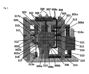
FIGURE 1 is a schematic drawing of a SF-CHIT cell power generator showing a
plasmadynamic converter in accordance with an embodiment of the present
disclosure.
FIGURE 2A is a schematic drawing of a SF-CIHT cell power generator showing a
photovoltaic converter in accordance with an embodiment of the present
disclosure.
FIGURE 2B is a schematic drawing of an arc H20 plasma cell power generator
showing
a photovoltaic converter in accordance with an embodiment of the present
disclosure.
FIGURE 2C is a schematic drawing of a SF-CIHT cell power generator showing an
optical distribution and the photovoltaic converter system in accordance with
an embodiment of
the present disclosure.
FIGURE 2C1 is a schematic drawing of a SF-CIHT cell power generator showing an
optical distribution and the photovoltaic converter system and auxiliary
system elements in
accordance with an embodiment of the present disclosure.
FIGURE 2C2 is a schematic drawing of a SF-CIHT cell power generator showing
the
ignition system and auxiliary system elements in accordance with an embodiment
of the present
disclosure.
FIGURE 2C3 is a schematic drawing of a SF-UHT cell power generator showing a
louver fan accordance with an embodiment of the present disclosure.
FIGURE 21) is a schematic drawing of a SF-CI.HT cell power generator showing
the
ignition system with an applicator wheel in accordance with an embodiment of
the present
disclosure.
12
SUBSTITUTE SHEET (RULE 26)
CA 02948640 2016-11-09
WO 2015/184252
PCT/US2015/033165
FIGURE 2E is a schematic drawing of a SF-I-FT cell power generator showing a
perspective inside of the optical distribution and photovoltaic converter
system comprising
semitransparent mirrors and photovoltaic cells in accordance with an
embodiment of the present
disclosure.
FIGURE 2F is a schematic drawing of a SF-CIIIT cell power generator showing
the
ignition system with mirrors in accordance with an embodiment of the present
disclosure.
FIGURE 20 is a schematic drawing of a SF-CIHT cell power generator showing the
placement of motors, pumps, and other components outside of the region housing
the roller
electrodes in accordance with an embodiment of the present disclosure.
FIGURE 201 is a schematic drawing of a SF-CIIIT cell power generator showing
the
placement of motors, pumps, and other components outside of the region housing
the roller
electrodes and further showing a fuel recirculation system with a louver fan
in accordance with
an embodiment of the present disclosure.
FIGURE 201a is a schematic drawing of a SF-CIFIT cell power generator showing
details of the rinsing line with jets and gas distribution ducts of a fuel
recirculation system in
accordance with an embodiment of the present disclosure.
FIGURE 2Glb is a schematic drawing of a SF-CIITI cell power generator showing
the
ducts of a fuel recirculation system with a perforated window gas diffuser in
accordance with an
embodiment of the present disclosure.
FIGURE 2G1.c is a schematic drawing of a SF-CIHT cell power generator showing
details of the gas distribution ducts and duct blower of a fuel recirculation
system in accordance
with an embodiment of the present disclosure.
FIGURE 2G:Id is a schematic drawing of a SF-CHTF cell power generator showing
details of a V-shaped screen in the walls of the slurry trough in accordance
with an embodiment
of the present disclosure.
FIGURE 2G1d1 is a schematic drawing of a SF-ClifT cell power generator showing
details of a pivoting bus bar ignition system in accordance with an embodiment
of the present
disclosure.
FIGURE 2Gle is a schematic of a piezoelectric actuator system in accordance
with an
embodiment of the present disclosure.
FIGURE 2Glel is a schematic drawing of a SF-CIHT cell power generator showing
details of fuel powder injection and ignition system in accordance with an
embodiment of the
present disclosure.
13
SUBSTITUTE SHEET (RULE 26)
CA 02948640 2016-11-09
WO 2015/184252
PCT/US2015/033165
FIGURE 2G1e2 is a schematic drawing of a SF-UHT cell power generator showing
details of fuel powder injection and ignition system with a blower and cyclone
separator fuel
recirculation-regeneration system in accordance with an embodiment of the
present disclosure.
FIGURE 2G1.e3 is a schematic drawing of a SF-CIEIT cell power generator
showing
details of fuel powder injection and ignition system with a blower and cyclone
separator fuel
recirculation-regeneration system in accordance with an embodiment of the
present disclosure:
FIGURE 2G1.e4 is a schematic drawing of a photoelectronic cell of the
transmission or
semitransparent type in accordance with an embodiment of the present
disclosure.
FIGURE 2G1e5 is a schematic drawing of a photoelectronic cell of the
reflective or
opaque type in accordance with an embodiment of the present disclosure.
FIGURE 2G1e6 is a schematic drawing of a photoelectronic cell of the
reflective or
opaque type comprising a grid anode or collector in accordance with an
embodiment of the
present disclosure.
FIGURE H1 is a schematic drawing of a SF-CIFIT cell power generator showing a
cell
capable of maintaining a vacuum, an ignition system having a railgun shot
injection system fed
by two transporters, augmented plasma railgun and gravity recovery systems, a
pelletizer, and a
photovoltaic converter system in accordance with an embodiment of the present
disclosure.
FIGURE H2 is a schematic drawing of a SF-CIHT cell power generator showing a
cell.
capable of maintaining a vacuum, an ignition system having a railgun shot
injection system fed
by two transporters, augmented plasma railgun and gravity recovery systems, a
pelletizer, and a
photovoltaic converter system showing the details of the ignition system and
it power supply in
accordance with an embodiment of the present disclosure.
FIGURE 113 is a schematic drawing of a SF-UHT cell power generator showing a
cell
capable of maintaining a vacuum, an ignition system having a railgun shot
injection system fed
by two transporters, augmented plasma railgun and gravity recovery systems, a
pelletizer, and a
photovoltaic converter system showing the details of the ignition system and
the photovoltaic
converter system in accordance with an embodiment of the present disclosure.
FIGURE 114 is a schematic drawing of a SF-UHT cell power generator showing a
cell
capable of maintaining a vacuum, an ignition system having a railgun shot
injection system fed
by two transporters, augmented plasma railgun and gravity recovery systems, a
pelletizer, and a
photovoltaic converter system showing the details of the ignition and
injection systems, the
ignition product recovery systems, and the pelletizer to form shot fuel in
accordance with an
embodiment of the present disclosure,
FIGURE Ti is a schematic drawing of a SF-CHIT cell power generator showing two
views of a cell capable of maintaining a vacuum, an ignition system having a
railgun shot
14
SUBSTITUTE SHEET (RULE 26)
CA 02948640 2016-11-09
WO 2015/184252
PCT/US2015/033165
injection system fed directly from a pelletizer, augmented plasma railgun and
gravity recovery
systems, the pelletizer, and a photovoltaic. converter system in accordance
with an embodiment
of the present disclosure.
FIGURE 12 is a schematic drawing of a SF-CIHT cell power generator showing a
cell
capable of maintaining a vacuum, an ignition system having a railgun shot
injection system fed
directly from a pelletizer, augmented plasma railgun and gravity recovery
systems, the pelletizer,
and a photovoltaic converter system in accordance with an embodiment of the
present disclosure,
FIGURE 13 is a schematic drawing of a SF-Cliff cell power generator showing a
cell
capable of maintaining a vacuum, an ignition system having a railgun shot
injection system fed
directly from a pelletizer, augmented plasma railgun and gravity recovery
systems, the pelletizer,
and a photovoltaic converter system showing the details of the railgun
injector and ignition
system and the photovoltaic converter system in accordance with an embodiment
of the present
disclosure.
FIGURE 14 is a schematic drawing of a SF-CIHT cell power generator showing a
cell
capable of maintaining a vacuum, an ignition system having a railgun shot
injection system fed
directly from a pelletizer, augmented plasma railgun and gravity recovery
systems, the pelletizer,
and a photovoltaic converter system showing the details of the injection
system having a
mechanical agitator, the ignition system, the ignition product recovery
systems, and the pelletizer
to form shot fuel in accordance with an embodiment of the present disclosure.
FIGURE 15 is a schematic drawing of a SF-CHIT cell power generator showing a
cell
capable of maintaining a vacuum, an ignition system having a railgun shot
injection system fed
directly from a pelletizer, augmented plasma railgun and gravity recovery
systems, the pelle.tizer,
and a photovoltaic converter system showing the details of the injection
system having a water
jet agitator, the ignition system, the ignition product recovery systems, and
the pelletizer to form
shot fuel in accordance with an embodiment of the present disclosure.
FIGURE 2J is a schematic of a thermal power system in accordance with an
embodiment
of the present disclosure.
FIGURE 3 is the absolute spectrum in the 120 nm to 450 MT' region of the
ignition of a
80 mg shot of silver comprising absorbed H2 and 1420 from gas treatment of
silver melt before
dripping into a water reservoir showing an average optical power of 172 kW,
essentially all in
the ultraviolet spectral region according to a fuel embodiment.
FIGURE 4 is the setup of the Parr 1341 calorimeter used for the energy balance
determination.
FIGURE 5 shows brilliant-light emitting expanding plasma formed from the high-
current
detonation of the solid fuel Cu + CuO + 1120 filmed at 6500 frames per second.
SUBSTITUTE SHEET (RULE 26)
CA 02948640 2016-11-09
WO 2015/184252
PCT/US2015/033165
FIGURE 6 shows the temporal full width half maximum light intensity of the
ignition
event of solid fuel Cu + H20 measured with a fast photodiode was 0.7 ms.
FIGURE 7 shows the Raman spectrum obtained on a In metal foil exposed to the
product
gas from a series of solid fuel ignitions under argon, each comprising .1.00
mg of Cu mixed with
30 mg of deionized water. Using the Thermo Scientific DXR SmartRaman
spectrometer and the
780 nin laser, the spectrum showed an inverse Raman effect peak at 1982 cm l
that matches the
free rotor energy of 112(114) (0,2414 eV) to four significant figures.
FIGURE 8 shows the Raman spectrum recorded on the In metal foil exposed to the
product gas from the argon-atmosphere ignition of SO mg of NII4NO3 sealed in
the DSC pan.
Using the Thermo Scientific DXR SmartRaman spectrometer and the 780 Mil laser
the spectrum
showed the H2(114) inverse Raman effect peak at 1988 cm4
.
FIGURE 9 shows the Raman-mode second-order photoluminescence spectrum of the
KOH-KC1 (1:1 wt%) getter exposed to the product gases of the ignition of solid
fuel samples of
100 mg Cu with 30 nig deionized water sealed in the DSC pan using a Horiba
Jobin 'Yvon
LabRam ARAMIS 325nm laser with a 1200 grating over a range of 8000-19,000 cm-1
Raman
shift.
FIGURE 10 shows a plot comparison between the theoretical energies and
assignments
given in Table 16 with the observed Raman spectrumõ
FIGURES 11A-B show the XPS spectra recorded on the indium metal foil exposed
to
gases from sequential argon-atmosphere ignitions of the solid fuel 100 mg Cu +
30 rng deionized
water sealed in the DSC pan. (A) A survey spectrum showing only the elements
In, C, 0, and
trace K peaks were present. (B) High-resolution spectrum showing a peak at
498.5 eV assigned
to 112(1/4) wherein other possibilities were eliminated based on the absence
of any other
corresponding primary element peaks.
FIGURES 12A-B show XPS spectra recorded on KOH-KCI. (1:1. wt%) getter exposed
to
gases from sequential argon-atmosphere ignitions of the solid fuel 85 mg of Ti
mixed with 30 mg
of deionized water sealed in the .DSC pan. (A) A survey spectrum showing only
the eiements K,
C, 0, N, and trace I peaks were present. (B) High-resolution spectrum showing
a peak at 496 eV
assigned to H2(1/4) wherein other possibilities were eliminated based on the
absence of any other
corresponding primary element peaks.
FIGURESA-B 13 show XPS spectra recorded on internal KOH-KCI (1:1 wt%) getter
exposed to gases argon-atmospheric ignition of the solid fuel 50 mg NII4NO3 +
KOH + KC!
(2:1:1 wt.) + 15 mg 1120 sealed in the aluminum DSC pan. (A) A survey spectrum
showing only
the elements K, Cu, CI, Si, Al, C. 0, and trace F peaks were present. (B) High-
resolution
spectrum showing a peak at 4% eV assigned to E2(1/4) wherein other
possibilities were
16
SUBSTITUTE SHEET (RULE 26)
CA 02948640 2016-11-09
WO 2015/184252
PCT/US2015/033165
eliminated based on the absence of any other corresponding primary element
peaks.
FIGURE 14 is the experimental setup for the high voltage pulsed discharge
cell. The
source emits its light spectra through an entrance aperture passing through a
slit, with the spectra
dispersed off a grazing-incidence grating onto a CCD detection system.
FIGURE 15 is the photograph of the high voltage pulsed discharge light source.
FIGURE 16 is the experimental setup for the ignition of conductive solid fuel
samples
and the recording of the intense plasma emission. The plasma expands into a
vacuum chamber
such that it becomes optically thin. The source emits its light spectrum
through an entrance
aperture passing through a slit, with the spectrum dispersed off a grazing-
incidence grating onto
CCD detection system.
FIGURES 17A-B is the transmission curves of filters for EUV light that blocked
visible
light, (A) The Al filter (150 nm thickness) having, a cutoff to short
wavelengths at -1.7 rum. (B)
The Zr filter (150 mil thickness) having high transmission at the predicted
H(1/4) transition
cutoff 10.1 nm.
FIGURES 18A-D are the emission spectra (2.5-45 am) comprising 1.000
superpositions
of electron-beam-initiated, high voltage pulsed gas discharges in helium or
hydrogen. Only
known helium and oxygen ion lines were observed with helium in the absence of
a continuum.
Continuum radiation was observed for hydrogen only independent of the
electrode, grating,
spectrometer, or number of CCD image superpositions. (A) Helium and hydrogen
plasmas
maintained with Mo electrodes and emission recorded using the CIA EUV grazing
incidence
spectrometer with the BLP 600 lines/mm grating. (B) Helium and hydrogen
plasmas maintained
with Ta electrodes and emission recorded using the CfA EUV grazing incidence
spectrometer
with the BLP 600 lines/ram grating. (C) Helium and hydrogen plasmas maintained
with W
electrodes and emission recorded using the CIA EUV grazing incidence
spectrometer with the
CIA 1200 lines/mm grating. (D) Helium and hydrogen plasmas maintained with W
electrodes
and emission recorded using the CfA. EUV grazing incidence spectrometer with
the BLP 600
lines/mm grating.
FIGURE 19 is the emission spectra (5-50 run) of electron-beam-initiated, high
voltage
pulsed discharges in helium-hydrogen mixtures with W electrodes recorded by
the EUV grazing
incidence spectrometer using the 600 lines/mm grating and 1000 superpositions
showing that the
continuum radiation increased in intensity with increasing hydrogen pressure.
FIGURES 20A4D are the emission spectra (5-40 rim) comprising 1000
superpositions of
electron-beam-initiated, high voltage pulsed gas discharges in hydrogen with
and without an Al
filter. No continuum radiation was observed from Al and Mg anodes. (A)
Hydrogen plasmas
maintained with an Al anode. (B) Hydrogen plasmas maintained with an Al anode
with the
17
SUBSTITUTE SHEET (RULE 26)
CA 02948640 2016-11-09
WO 2015/184252
PCT/US2015/033165
spectrum recorded with an Al filter. (C) Hydrogen plasmas maintained with an
Mg anode, (D)
Hydrogen plasmas maintained with an Mg anode with the spectrum recorded with
an Al filter.
FIGURES 21A-B shows high-speed photography of brilliant light-emitting
expanding
plasma formed from the low voltage, high current detonation of the solid
fuels. (A) Cu + 010
H20 filmed at 6500 frames per second. The white-blue color indicates a large
amount of UV
emission from a blackbody with a temperature of 5500-6000 K, equivalent to the
Sun's. (B)
55.9 mg Ag (10 at%) coated on Cu (87 wt%) Bal2 2H20 (13 wt%), filmed at 17,791
frames per
second with a VI waveform that shows plasma at a time when there was no
electrical input
power (noted by the yellow vertical line), and no chemical reaction was
possible. The plasma
persisted for 21,9 ms while the input power was zero at 1.275 ms. The peak
reactive voltage
measured at the welder connection to the bus bar was about 20 V, and the
corresponding voltage
at the other end near the fuel was < 15 V.
FIGURE 22 shows the plasma conductivity as a function of time following
detonation of
the solid fuel /00 nut 4- 30 mg H20 sealed in the DSC pan at a pair of
conductivity probes spaced
1..5875 cm apart. The time delay between the pair of conductivity probes was
measured to be 42
ps that. corresponded to a plasma expansion velocity of 378 m/s which averaged
to sound speed,
343 m/s, over multiple measurements.
FIGURE 23 shows the intensity-normalized, superposition of visible spectra of
the
plasmas formed by the low voltage, high current ignition of solid fuels 100 mg
Ti 30 mg H20
and 100 mg Cu + 30 mg H20 both sealed in the DSC pan, compared with the
spectrum of the
Sun's radiation at the Earth's surface. The overlay demonstrates that all the
sources emit
blackbody radiation of about 5000-6000 K, but the solid fuel blackbody
emission (before
normalization) is over 50,000 times more intense than sunlight at the Earth's
surface.
FIGURE 24 shows the fast photodiode signal as a function of time capturing the
evolution of the light emission following the. ignition event of the solid
fuel 100 mg Ti + 30 nig
H20 sealed in the DSC pan. The temporal full width half maximum light
intensity measured
with the fast photodiode was 0.5 ms.
FIGURE 25 shows the visible spectrum of the plasma formed by the low voltage,
high
current ignition of solid fuel paraffin wax sealed in the DSC pan taken at 427
cm from the blast.
This source also emits blackbody radiation of about 5000-6000 K, similar to
the spectra of the
Sun and I120-based solid fuels shown in Figure 23.
FIGURES 26A-B show the high resolution, visible spectra in the spectral region
of the H
Balmer a line measured using the Jobin Yvon Horiba 1.250 M spectrometer with a
20 pm slit,
(A) The full width half maximum (FWHM) of the 632.8 nm HeNe laser line was
0.07 A that
confirmed the high spectral resolution. (B) The FWHM of the Balmer a line from
the emission
18
SUBSTITUTE SHEET (RULE 26)
CA 02948640 2016-11-09
WO 2015/184252
PCT/US2015/033165
of the ignited solid fuel 100 mg Cu 4- 30 mg H20 sealed in the DSC pan was
22.6 A
corresponding to an electron density of 3.96 X 10²³/m3. The line was shifted
by +1.2 A. The
plasma was almost completely ionized at the blackbody temperature of 6000 K.
The Balmer (x.
line width from the emission of the ignited solid fuel 100 mg Ti + 30 mg H.20
sealed in the DSC
pan could not be measured due to the excessive width, significantly greater
than 24 A
corresponding to a 100% ionized plasma at a blackbody temperature of at least
5000 K.
FIGURE 27 shows the optical energy density spectrum (350 run to 1000 nm)
measured
with the Ocean Optics spectrometer by temporal integration of the power
density spectrum taken
over a time span of 5s to collect all of the optical energy from the 0.5 31Is
light emission pulse of
the ignited solid fuel 100 mg Ti + 30 mg H20 sealed in a DSC pan. The energy
density obtained
by integrating the energy density spectrum was 5.86 Jim2 recorded at a
distance of 353,6 cm.
FIGURE 28 shows the calibration emission spectrum (0-45 nm) of a high voltage
pulsed
discharge in air (100 inTorr) with NV electrodes recorded using the EUV
grazing incidence
spectrometer with the 600 lines/mm grating and Al filters showing that only
known oxygen and
nitrogen lines and the zero order peak were observed in the absence of a
continuum.
FIGURE 29 shows the emission spectra (0-45 nm) of the plasma emission of the
conductive Ni0OH pellet ignited with a high current source having an AC peak
voltage of less
than 15 V recorded with two Al filters alone and additionally with a quartz
filter. Only EUV
passes the Al filters, and the EUV light is blocked by the quartz filter. A
strong EUV continuum
with secondary ion emission was observed in the region 17 to 45 nm n with a
characteristic Al
filter notch at 1.0 to 17 rim as shown in Figure 17A. The EUV spectrum (0-45
nm) and intense
zero order peak were completely cut by the quartz filter confirming that the
solid fuel plasma
emission was EUV.
FIGURE 30 shiows the emission spectrum (0-45 nm) of the plasma emission of a 3
mm
pellet of the conductive Ag (10%)-Cuff3a12 2F110 fuel ignited with a high
current source having
an AC peak voltage of less than 15 V recorded with two Al filters with a
superimposed
expansion to present details. A strong EUV continuum with secondary ion
emission was
observed in the region 17 to 45 nm with a characteristic Al filter notch at
1.0 to 17 nm as shown
in Figure 17A.
FIGURE 31 shows the emission spectrum (0-45 nm) of the plasma emission of a 3
mm
pellet of the conductive Ag (10%)-CulBa12 21120 fuel ignited with a high
current source having
an AC peak voltage of less than 15 V recorded with two Al filters with a
superimposed
expansion to present details. A strong EUV continuum with secondary ion
emission was
observed having a 10..1 nm cutoff as predicted by Eqs. (230) and (233) that
was transmitted by
the zirconium filter as shown in Figure .17B.
19
SUBSTITUTE SHEET (RULE 26)
CA 02948640 2016-11-09
WO 2015/184252
PCT/US2015/033165
FIGURE 32 shows the emission spectra (0-45 inn) of the plasma emission of
paraffin
wax sealed in the conductive DSC pan ignited with a high current source having
an AC peak
voltage of less than 15 V recorded with the two Al filters alone and
additionally with a quartz
filter. A zero order BUY peak was observed. The zero order peak was completely
cut by the
quartz filter confirming that the solid fuel plasma emission was BUY.
FIGURE 33 shows the emission spectra (0-45 nm) of the plasma emission of
conductive
Ni0OH pellet ignited with a high current source having an AC peak voltage of
less than 15 V
recorded with two Al filters alone and additionally with a quartz filter. An
extraordinarily
intense zero order peak and BIN continuum was observed due to -RN photon
scattering of the
massive emission and large slit width of 100 pm. The emission comprised 2.32 X
101 photon
counts that corresponded to a total distance-and-solid-angle-corrected energy
of 1.48 J of EUV
radiation. The EUV spectrum (0-45 nm) and zero order peak were completely cut
by the quartz
filter confirming that the solid fuel plasma emission was -EUV:
FIGURE 34 shows the emission spectra (0-45 rim) of the plasma emission of 5 mg
energetic material NII4NO3 sealed in the conductive Al DSC pan ignited with a
high current
source having an AC peak voltage of less than 15 V recorded with two Al
filters alone and
additionally with a quartz filter. An extraordinarily intense zero order peak
was observed as
shown by the comparison with H2 pinch discharge emission (lower trace). The
emission
corresponded to a total distance-and-solid-anale-corrected energy of 125 I of
BUY radiation.
The BUY spectrum (0-45 rim) and zero order peak were completely cut by the
quartz filter
confirming that the solid fuel plasma emission was EUV.
FIGURE 35 shows an exemplary model of the BUY continuum spectrum of the
photosphere of a white dwarf using a temperature of 50,000 K and a number
abundance of Hefli
lir showing the He II and H I Lyman absorption series of lines at 22.8 rim
(228 A) and 91.2
rim (912 A), respectively. From M. A. Barstow and J. B. Holberg, Extreme
Ultraviolet
Astronomy, Cambridge Astrophysics Series 37, Cambridge University Press,
Cambridge, (2003).
FIGURE 36 shows the Skylab (Harvard College Observatory spectrometer) average
extreme ultraviolet spectra of the Sun recorded on a prominence (Top), quiet
Sun-center
(Middle), and corona above the solar limb (Bottom) from M. Stix, The Sun,
Springer-Verlag,
Berlin, (1991), Figure 9.5, p. 321. In the quiet Sun-center spectrum, the 91.2
nm continuum to
longer wavelengths is expected to be prominent and is observed despite
attenuation by the
corona' gas. The continuum was greatly reduced in the prominence and the
corona wherein the
H concentration was much reduced and absent, respectively. The emission from
chromospheric
lines and the continuum was also severely attenuated in the corona. The
strongest lines in the
coronal spectrum and to a lesser extent the prominence are multiply ionized
ions such as the
SUBSTITUTE SHEET (RULE 26)
CA 02948640 2016-11-09
WO 2015/184252
PCT/US2015/033165
doublets of Ne VIII, Mg X, or Si X/I that could be due to absorption of high
energy continuum
radiation rather than thermal excitation. From E. M. Reeves, E. C. M. Huber,
G. J. Timothy,
"Extreme UV spectroheliometer on the Apollo telescope mount", Applied Optics,
Vol. 16,
(1977), pp. 837-848.
FIGURE 37 shows the dark matter ring in galaxy cluster. This Hubble Space
Telescope
composite image shows a ghostly "ring" of dark matter in the galaxy cluster Cl
0024+17. The
ring is one of the strongest pieces of evidence to date for the existence of
dark matter, a prior
unknown substance that pervades the universe. Courtesy of NASA/ESA, M.J. Jee
and H. Ford
(Johns Hopkins University), Nov. 2004.
Disclosed here in are catalyst systems to release energy from atomic hydrogen
to form
lower energy states wherein the electron shell is at a closer position
relative to the nucleus. The
released power is harnessed for power generation and additionally new hydrogen
species and
compounds are desired products. These energy states are predicted by classical
physical laws
and require a catalyst to accept energy from the hydrogen in order to undergo
the corresponding
energy-releasing transition.
Classical physics gives closed-form solutions of the hydrogen atom, the
hydride ion, the
hydrogen molecular ion, and the hydrogen molecule and predicts corresponding
species having
fractional principal quantum numbers. Using Maxwell's equations, the structure
of the electron
was derived as a boundary-value problem wherein the electron comprises the
source current of
time-varying electromagnetic fields during transitions with the constraint
that the bound n 1
state electron cannot radiate energy. A reaction predicted by the solution of
the H atom involves
a resonant, nonradiative energy transfer from otherwise stable atomic hydrogen
to a catalyst
capable of accepting the energy to form hydrogen in lower-energy states than
previously thought
possible. Specifically, classical physics predicts that atomic hydrogen may
undergo a catalytic
reaction with certain atoms, excimers, ions, and diatomic hydrides which
provide a reaction with
a net enthalpy of an integer multiple of the potential energy of atomic
hydrogen, Eh = 27,2 eV
where E, is one Hartree. Specific species (e.g. He', Art, K, Li, Ha, and
NaH, OH, Sii,
SeH, nascent H20, nH (n.integer)) identifiable on the basis of their known
electron energy levels
are required to be present with atomic hydrogen to catalyze the process. The
reaction involves a
nonradiative energy transfer followed by q = 13.6 eV continuum emission or q
.13.6 eV transfer
toll to form extraordinarily hot, excited-state H and a hydrogen atom that is
lower in energy
than unreacted atomic hydrogen that corresponds to a fractional principal
quantum number. That
is, in the formula for the principal energy levels of the hydrogen atom:
7
e- 13.598 eV
" 1128HE ha if n'=
21
SUBSTITUTE SHEET (RULE 26)
CA 02948640 2016-11-09
WO 2015/184252 PCT/US2015/033165
n =1,2,3,.,. (2)
where ail is the Bohr radius for the hydrogen atom (52.947 pm), e is the
magnitude of the
charge of the electron, and E0 is the vacuum permittivity, fractional quantum
numbers:
where p .137 is an integer (3)
2 3' 4 p
replace the well known parameter n integer in the Rydberg equation for
hydrogen excited
states and represent lower-energy-state hydrogen atoms called "hydrinos."
Then, similar to an
excited state having the analytical solution of Maxwell's equations, a hydrino
atom also
comprises an electron, a proton, and a photon. However, the electric field of
the latter increases
the binding corresponding to desorption of energy rather than decreasing the
central field with
the absorption of energy as in an excited state, and the resultant photon-
electron interaction of
the hydrino is stable rather than radiative.
1.
The n 1 state of hydrogen and the n=
states of hydrogen are nonradiative, but
integer
a transition between two nonradiative states, say n = Ito n =1/ 2, is possible
via a nonradiative
energy transfer, Hydrogen is a special case of the stable states given by Eqs,
(1) and (3) wherein
the corresponding radius of the hydrogen or hydrino atom is given by
r (4)
where p = 1,2,3,õ.. In order to conserve energy, energy must be transferred
from the hydrogen
atom to the catalyst in units of
m = 27.2 eV , (5)
a
an , d the radius transitions to ___________________ .
The catalyst reactions involve two steps of energy release: a
p
nonradiative energy transfer to the catalyst followed by additional energy
release as the. radius
decreases to the corresponding stable final state. It is believed that the
rate of catalysis is
increased as the net enthalpy of reaction is more closely matched to ?Ti 27.2
eV. It has been
found that catalysts having a net enthalpy of reaction within 10% preferably
5% , of
in, 27.2 eV are suitable for most applications. In the case of the catalysis
of hydrino atoms to
lower energy states, the enthalpy of reaction of in = 27,2 eV (Eq. (5)) is
relativistically corrected
by the same factor as the potential energy of the hydrino atom.
Thus, the general reaction is given by
a
m = 27.2 eV 4- Cat."' + ¨> Cat("+. .4- re- + * a -I- in-
27.2 eV (6)
P (n+ P)
22
SUBSTITUTE SHEET (RULE 26)
CA 02948640 2016-11-09
WO 2015/184252 PCT/US2015/033165
atl
H *=el ______________________ +[(rn + p)2 ¨ p2] -1.3.6 eV -- m = 27.2 eV
(7)
(m + p) ( m + p)
- . - -
Cai(q+r)+ + re- ¨*Catq' + m = 27.2 eV and (8)
the overall reaction is
i a a If
+ [(rn + p)2 ¨ p2 i = 13.6 eV (9)
I P _ (In+ P) .
_
_
q, r, m ,. and p are integers. II * . a fl , has the radius of the hydrogen
atom
[
(m + p, ) _
(corresponding to 1 in the denominator) and a central field equivalent to (m +
p) times that of a
aii 1
proton, and II µ is the corresponding stable state with the radius of . __
, that of if.
(m + p ) (m + p)
As the electron undergoes radial acceleration from the radius of the hydrogen
atom to a radius of
I
this distance, energy is released as characteristic light emission or as third-
body kinetic
(in + p)
energy. The emission may be in the form of an extreme-ultraviolet continuum
radiation having
91/
an edge at [(p + m)2 ¨ p2 ¨ 2m] = 13.6 eV or ----7------;------- nm and
extending to longer
[(m+ p) = ¨ p = ¨ 2rn]
wavelengths: In addition to radiation, a resonant kinetic energy transfer to
form fast H may
occur. Subsequent excitation of these fast H (ti = I) atoms by collisions with
the background H2
followed by emission of the corresponding H (n = 3) fast atoms gives rise to
broadened Balmer
a emission. Alternatively, fast H is a direct product of H or hydrino serving
as the catalyst
wherein the acceptance of the resonant energy transfer regards the potential
energy rather than
the ionization energy. Conservation of energy gives a proton of the kinetic
energy corresponding
to one half the potential energy in the former case and a catalyst ion at
essentially rest in the
latter case: The H recombination radiation of the fast protons gives rise to
broadened Balmer a
emission that is disproportionate to the inventory of hot hydrogen consistent
with the excess
power balance.
In the present disclosure the terms such as hydrino reaction, H catalysis, H
catalysis
reaction, catalysis when referring to hydrogen, the reaction of hydrogen to
form hydrinos, and
hydrino formation reaction all refer to the reaction such as that of Eqs. (6-
9)) of a catalyst
defined by Eq. (5) with atomic H to form states of hydrogen having energy
levels given by Eqs.
(I) and (3). The corresponding terms such as hydrino reactants, hydrino
reaction mixture,
catalyst mixture, reactants for hydrino formation, reactants that produce or
form lower-energy
23
SUBSTITUTE SHEET (RULE 26)
CA 02948640 2016-11-09
WO 2015/184252
PCT/US2015/033165
state hydrogen or hydrinos are also used interchangeably when referring to the
reaction mixture
that performs the catalysis of H to H. states or hydrino states having energy
levels given by Eqs.
(1) and (3).
The catalytic lower-energy hydrogen transitions of the present disclosure
require a
catalyst that may be in the form of an endothermic chemical reaction of an
integer in of the
potential energy of uncatalyzed atomic hydrogen, 27.2 eV, that accepts the
energy from atomic
H to cause the transition. The endothermic catalyst reaction may be the
ionization of one or
more electrons from a species such as an atom or ion (e.g. in 3 for Li _)
and may further
comprise the concerted reaction of a bond cleavage with ionization of one or
more electrons
from one or more of the partners of the initial bond (e.g. in 2 for NaH .Na'4"
+ H). He+
fulfills the catalyst criterion¨a chemical or physical process with an
enthalpy change equal to an
integer multiple of 27.2 eV since it ionizes at 54,417 eV, which is 2 27.2 eV.
An integer
number of hydrogen atoms may also serve as the catalyst of an integer multiple
of 27.2 eV
enthalpy. Hydrogen atoms 11(1/ p) p can undergo further transitions to
lower-
energy states given by Eqs, (1) and (3) wherein the transition of one atom is
catalyzed by one or
more additional H atoms that resonantly and nonradiatively accepts in- 27.2 eV
with a
concomitant opposite change in its potential energy. The overall general
equation for the
transition of .11 p) to H(1/ (in + p)) induced by a resonance transfer of
in 27,2 eV to
H (11 p') is represented by
l'
H (1/ p H (1. .p) H + H (1. / (in + p)) + I2 pm + inc p' .) .6
(10)
Hydrogen atoms may serve as a catalyst wherein in = 1, m = 2, and in = 3 for
one, two,
and three atoms, respectively, acting as a catalyst for another. The rate for
the two-atom-
catalyst, 211, may be high when extraordinarily fast 11 collides with a
molecule to form the 21-I
wherein two atoms resonantly and nonradiatively accept 54.4 eV from a third
hydrogen atom of
the collision partners. By the same mechanism, the collision of two hot 112
provide 3H to serve
as a catalyst of 327.2 eV for the fourth. The EIN continua at 22,8 nin and
10,1 mn,
extraordinary (>100 eV) Balmer a line broadening, highly excited H states, the
product gas
H2 (it 4) , and large energy release is observed consistent with predictions.
H(1/4) is a preferred hydrino state based on its multipolarity and the
selection rules for its
formation. Thus, in the case that 11(1/3) is formed, the transition to H(114)
may occur rapidly
catalyzed by H according to Eq. (10). Similarly, H(1./4) is a preferred state
for a catalyst energy
greater than or equal to 81.6 eV corresponding to m.3 in Eq. (5). In this case
the energy transfer
to the catalyst comprises the 81.6 eV that forms that 11*(1/4) intermediate of
Eq. (7) as well as an
integer of 27.2 eV from the decay of the intermediate. For example, a catalyst
having an
24
SUBSTITUTE SHEET (RULE 26)
CA 02948640 2016-11-09
WO 2015/184252
PCT/US2015/033165
enthalpy of 108,8 eV may form I1(1/4) by accepting 81.6 eV as well as 27.2 eV
from the
1-1*(1/4) decay energy of 122.4 eV. The remaining decay energy of 95.2 eV is
released to the
environment to form the preferred state H(1/4) that then reacts to form
142(114).
A suitable catalyst can therefore provide a net positive enthalpy of reaction
of
m = 27,2 eV That is, the catalyst resonantly accepts the nonradiative energy
transfer from
hydrogen atoms and releases the energy to the surroundings to affect
electronic transitions to
fractional quantum energy levels. As a consequence of the nonradiative energy
transfer, the
hydrogen atom becomes unstable and emits further energy until it achieves a
lower-energy
nonradiative state having a principal energy level given by Eqs. (1) and (3).
Thus, the catalysis
releases energy from the hydrogen atom with a commensurate decrease in size of
the hydrogen
atom, r, = na where n is given by Eq.. (3). For example, the catalysis of J-1
(n ,== 1) to
1
/ 4) releases 204 eV , and the hydrogen radius decreases from a,, to a
' 4
The catalyst product, 1-1(1 / ,
may also react with an electron to form hydrino hydride
ion IF( p), or two HO / p) may react to form the corresponding molecular
hydrino
fir,, (1/ p). Specifically, the catalyst product, If (1 / p) , may also react
with an electron to form
a novel hydride ion 11-- (1 p) with a binding energy E
qs(s +1) itgoe- f:
(11)
+ ........................... "1: a11 3 1+ NIS(S +
a ¨
=
where p = integer > s 11 2, h is Planck's constant bar, JJ is the permeability
of vacuumm in
in, is the mass of the electron, p, is the reduced electron mass given by Ai,=
where
t,'
mp is the mass of the proton, is
the Bohr radius, and the ionic radius is ¨ _ is (s +1))
P \
. From Eq. (11), the calculated ionization energy of the hydride ion is
0.75418 eV, and the
experimental value is 6082.99 0.15 cm (0.75418 eV), The binding energies of
hydrino
hydride ions may be measured by X-ray photoelectron spectroscopy (XPS).
Upfield-shifted NMR peaks are direct evidence of the existence of lower-energy
state
hydrogen with a reduced radius relative to ordinary hydride ion and having an
increase in
diamagnetic shielding of the proton. The shift is given by the :sum of the
contributions of the
SUBSTITUTE SHEET (RULE 26)
CA 02948640 2016-11-09
WO 2015/184252 PCT/US2015/033165
diamagnetism. of the two electrons and the photon field of magnitude p
GUTCP Eq
(7.87));
oe2
.................................... po + _________________________ = -
(p29.9 p21..59 X l.0) ppm (12)
Pima+ )
r 0 8 ,
where the first term applies to ir with p= 1 and p= integer >1 for /-/- (1/ p)
and a is the
fine structure constant. The predicted hydrino hydride peaks are
extraordinarily upfield shifted
relative to ordinary hydride ion. In an embodiment, the peaks are upfield of
TMS. The NMR
shift relative to TMS may be greater than that known for at least one of
ordinary Fr, H, H2, or If
alone or comprising a compound. The shift may be greater than at least one of
0, -1, -2, -3, -4, -
5, -6, -7, -8, -9, -1.0, -11, -12, -13, -14, -15, -16, -17, -18, -19, -20, -
21, -22, -23, -24, -25, -26, -
27, -28, -29, -30, -31, -32, -33, -34, -35, -36, -37, -38, -39, and -40 ppm.
The range of the
absolute shift relative to a bare proton, wherein the shift of TMS is about -
31.5 relative to a bare
proton, may be -(p29.9 p22.74) ppm (Eq. (1.2)) within a range of about at
least one of 5 ppm,
ppm, 20 ppm, 30 ppm, 40 ppm, 50 ppm, 60 ppm, 70 ppm, 80 ppm, 90
ppm, and .100 ppm. The range of the absolute shift relative to a bare proton
may be -(p29.9
p21,59 X 10 ppm (Eq. (12)) within a range of about at least one of about 0.1%
to 99%, I.% to
50%, and 1% to 10%. in another embodiment, the presence of a hydrino species
such as a
hydrino atom, hydride ion, or molecule in a solid matrix such as a matrix of a
hydroxide such as
NaOH or KOH causes the matrix protons to shift upheld. The matrix protons such
as those of
NaOH or KOH may exchange. In an embodiment, the shift may cause the matrix
peak to be in
the range of about -0.1 ppm to -5 ppm relative to TMS. The NMR determination
may comprise
magic angle spinning iH nuclear magnetic resonance spectroscopy (MAS '11 NMR).
11 (1 i.' pi may react with a proton and two 11(1/ p) may react to form I/2
(1. p) and
,
112(1/ p), respectively. The hydrogen molecular ion and molecular charge and
current density
functions, bond distances, and energies were solved from the Laplacian in
ellipsoidal coordinates
with the constraint of nonradiation.
(flaqi
-4 ---;(R, -(R -aC6 )4- (4- ri)R -(1?,-)= 0 (13)
The total energy ET of the hydrogen molecular ion having a central field of
+pe at each
focus of the prolate spheroid molecular orbital is
26
SUBSTITUTE SHEET (RULE 26)
CA 02948640 2016-11-09
WO 2015/184252 PCT/US2015/033165
r ..
; r"--1=s,s,-,77,=-.= "1
,
i
Ii 421E. 12a,. )3
I 1 m
,
__________________ (41n3 1 21n3) 1+ p = ,
- 87re a m c-
f;-: ._ ....,.,õ: . 0 1 i
= , .. . .
1. r , 2 (14)
r,e
. r . ne2
,-
,
1
ha 3a., 4re .. 1' 8rp h
0
1 = p , p
2 = 12 :1
,
=::: -p216,13392 eV- P30.118755 eV
where p is an integer, c is the speed of light in vacuum, and p is the.
reduced nuclear mass,
The total energy of the hydrogen molecule having a central field of +pe at
each focus of the
prolate spheroid molecular orbital is
f .:
r
. i e
. .
. i I 4.7rE a' i 0
0
F.- \---------
e' i= . i=-= .r." q2 I v2 +1 1 y
m
................. '-= . = - 2v2 , - A./24. . In , sE2 la- p.1¨
.,'
. /2
'_N ¨/ . = M C' :
-, ,,,,,,,,,,,,,,,,, õõõõõõõõõõõõõõõõõõõ,
_L.. '.. ¨ zi ===
! ....... ,
1 ................... pe2 Pc 2 .
(15)
i ....1 ..
0..
-.,,- ,
I Q 1 a - [. 1 N
1 urCE 0 14- 1--- at., .
. ,
; I P . -q2 i- .=== I 8rE - .==
'
P,.
2 P
= - 1)231.351 eV - p30.326469 eV
The bond dissociation energy, ED , of the hydrogen molecule H2 (I / p) is the
difference
between the total energy of the corresponding hydrogen atoms and Er
ED = E(2H (1 I p))- ET (16)
where
E(2.11(1,1 p)) = -p227,20 eV (17
E1, is given by Eqs. (1647) and (15):
E D = -p227.20 eV - Er
. -p227.20 eV -(- p231.351 ell. - p30.326469 ell) (18)
. p24.151 eV + p0.326469 eV
27
SUBSTITUTE SHEET (RULE 26)
CA 02948640 2016-11-09
WO 2015/184252
PCT/US2015/033165
I 2(1 p) may be identified by X-ray photoelectron spectroscopy (XPS) wherein
the
ionization product in addition to the ionized electron may be at least one of
the possibilities such
as those comprising two protons and an electron, a hydrogen (H) atom, a
hydrino atom, a.
molecular ion, hydrogen molecular ion, and 112(11 p) wherein the energies may
be shifted by
the matrix.
The NMR of catalysis-product gas provides a definitive test of the
theoretically predicted
chemical shift of H 2(1 / p) In general, the ti MAR resonance of H2(1/ p) is
predicted to be
upfield from that of H2 due to the fractional radius in elliptic coordinates
wherein the electrons
AB
are significantly closer to the nuclei. The predicted shift, , for
H (11 ps) is given by the
2 ,
sum of the contributions of the diamagnetism of the two electrons and the
photon field of
magnitude p (Mills GUTCP Eqs. (1.1.415-11.41.6)):
AIL Ai'7
+
Ile
4-21n r .. (1+ pal) (19)
2 - )36aorn,
AB
________ - -(1)28.01+ p21.49 X 10-) ppm (20)
where the first term applies to H.2 with p = 1 and p = integer >1 for "2 / p)
. The
experimental absolute 1/2 gas-phase resonance shift of -28.0 ppm is in
excellent agreement with
the predicted absolute gas-phase shift of -28.01 ppm (Eq. (20)). The predicted
molecular
hydrino peaks are extraordinarily upfield shifted relative to ordinary H2. In
an embodiment, the
peaks are upfield of TMs. The NMR shift relative to TIVIS may be greater than
that known for at
least one of ordinary If, H,112, or H+ alone or comprising a compound. The.
shift may be greater
than at least one of 0,4, -2, -3, -4, -5, -6, -7, -8, -9, -10, -11, -12, -13, -
14, -15, -16, -17, -18, -19,
-20, -21, -22, -23, -24, -25, -26, -27, -28, -29, -30, -31, -32, -33, -34, -
35, -36, -37, -38, -.39, and -
40 ppm. The range of the absolute shift relative to a bare proton, wherein the
shift of TMS is
about -31.5 ppm relative to a bare proton, may be -(p28.01 p2156) ppm (Eq,
(20)) within a
range of about at least one of 5 ppm, 10 ppm, 20 ppm, 30 ppm, 40 ppm,
50 ppm,
60 ppm, 70 ppm, 80 ppm, 90 ppm, and 100 ppm. The range of the absolute
shift
relative to a bare proton may be -(p28.01 p21,49 X 10-3) ppm (Eq. (20)) within
a range of about
at least one of about 0.1% to 99%, 1c';6 to 50%, and 1% to 1.0%.
The vibrational energies, E,, for the v -0 to v =1 transition of hydrogen-type
molecules 112(1/ p3 are
p20.515902 eV (21)
28
SUBSTITUTE SHEET (RULE 26)
CA 02948640 2016-11-09
WO 2015/184252
PCT/US2015/033165
where p is an integer
The rotati.onal energies, E, for the J to J +1. transition of hydrogen-type
molecules
H2 (1 / p) are
h2
E= Ej+,¨ E j= +1. = p2(..1 +1)0.01509 eV (22)
where p is an integer and I is the moment of inertia. Ro-vibrational emission
of H2 / 4) was
observed on e-beam excited molecules in gases and trapped in solid matrix.
The p2 dependence of the rotational energies results from an inverse p
dependence of
the internuclear distance and the corresponding impact on the moment of
inertia I , The
predicted internuclear distance 2c for /12(1.1 ls
2c) ____________________________________________________________ (23)
At least one of the rotational and vibration energies of If1(1/p) may be
measured by at
least one of electron-beam excitation emission spectroscopy, Raman
spectroscopy, and Fourier
transform infrared (FTIR) spectroscopy. H2(1/p) may be trapped bt a matrix for
measurement
such as in at least one of MOH, MX, and M2CO3 (M = alkali; X = halide) matrix.
1. Catalysts
Fle+, Ark, Sr', Li, K, Nall, di (n = integer), and H20 are predicted to serve
as catalysts
since they meet the catalyst criterion a chemical or physical process with
an enthalpy change
equal to an integer multiple of the potential energy of atomic hydrogen, 27.2
eV , Specifically, a
catalytic system is provided by the ionization of t electrons from an atom
each to a continuum
energy level such that the sum of the ionization energies of the t electrons
is approximately
m 27.2 eV where in is an _integer. Moreover, further catalytic transitions may
occur such as in
the case wherein 11(1./2) is first formed: n = ¨¨ and so on. Once catalysis
2 3' 3 44 5'
begins, hydrinos autocatalyze further in a process called disproportionation
wherein H or H(1./p)
serves as the catalyst for another H or 14( lip') (p may equal p').
Hydrogen and hydrinos may serves as catalysts. Hydrogen atoms
H.(1/ p) p= .1,2,3,.,..137 can undergo transitions to lower-energy states
given by Eqs. (1) and
(3) wherein the transition of one atom is catalyzed by a second that
resonantly and nonradiatively
accepts in 272 eV with a concomitant opposite change in its potential energy.
The overall
general equation for the transition of H / p) to HO/ (rn + pi) induced by a
resonance transfer
of m= 27.2 eV to 11(1/ p) is represented by Eq. (10), Thus, hydrogen atoms may
serve as a
29
SUBSTITUTE SHEET (RULE 26)
CA 02948640 2016-11-09
WO 2015/184252
PCT/US2015/033165
catalyst wherein m.:1, in. 2, and m:::: 3 for one, two, and three atoms,
respectively, acting as
a catalyst for another. The rate for the two or three-atom-catalyst case would
be appreciable
only when the H density is high. But, high H densities are not uncommon. A
high hydrogen
atom concentration permissive of 2H or 311 serving as the energy acceptor for
a third or fourth
may be achieved under several circumstances such as on the surface of the Sun
and stars the to
the temperature and gravity driven density, on metal surfaces that support
multiple monolayers,
and in highly dissociated plasmas, especially pinched hydrogen plasmas.
Additionally, a three
-
body H interaction is easily achieved when two II atoms arise with the
collision of a hot H
with H.,. This event can commonly occur in plasmas having a large population
of
extraordinarily fast H. This is evidenced by the unusual intensity of atomic
Ft emission, In such
cases, energy transfer can occur from a hydrogen atom to two others within
sufficient proximity,
being typically a few angstroms via multipole coupling. Then, the reaction
between three
hydrogen atoms whereby two atoms resonantly and nonradiatively accept 54.4 eV
from the third
hydrogen atom such that 2/1 serves as the catalyst is given by
..
a
54.4 eV 2/1 + H .---> 2/1f':(a! + 2e- + H * ¨4- +54A eV (24)
-- -
,-- -,
11 *-1-6 ----) 11-11-61 . 4- 544 eV
[3 I. 3 .. (2$)
Ur; + 2e ----> 211 +54.4 eV (26)
jam
And, the overall reaction is
a
H ---) H ¨IL +[32 ¨11=116 eV (27)
3
a '
wherein H * --12-`= has the radius of the hydrogen atom and a central field
equivalent to 3 times
3
aõ
that of a proton and H --IL is the corresponding stable state with the radius
of 1/3 that of H.
3
As the electron undergoes radial acceleration from the radius of the hydrogen
atom to a radius of
1/3 this distance, energy is released as characteristic light emission or as
third-body kinetic
energy.
- a,,71 .
In another II -atom catalyst reaction involving a direct transition to ¨ i
state, two hot
4 i -
112 molecules collide and dissociate such that three 11 atoms serve as a
catalyst of 3, 27.2 eV
for the fourth. Then, the reaction between four hydrogen atoms whereby three
atoms resonantly
SUBSTITUTE SHEET (RULE 26)
CA 02948640 2016-11-09
WO 2015/184252
PCT/US2015/033165
and nonradiatively accept 81.6 eV from the fourth hydrogen atom such that 3H
serves as the
catalyst is given by
r-
a .
81.6 eV. + 3H + .H 311+, + 3e- +1/ * + 81.6 eV (28)
psi 4
H * H +122A eV (29)
4 i 4
L
311+ + 311 + 81 6 eV (30)
ci
And, the overall reaction is
H H 1+ [42 ¨1.2] .13.6 eV (31)
4 :
r
a
The extreme-ultraviolet continuum radiation band due to the H "
intermediate of
4
-
Eq. (28) is predicted to have short wavelength cutoff at 122.4 eV (10.1 nm)
and extend to longer
wavelengths. This continuum band was confirmed experimentally. In general, the
transition of
H to II a,õ
= due by the acceptance of in = 272 eV gives a continuum band with a short
wavelength cutoff and energy Ei given by
n -4 H{ ...................... 4 "
1
p 1)
r
tn2 .1.3.6 eV (32)
"
a
Lp-m+11
- - =. 91;2 no? (33)
H
,p=m+
and extending to longer wavelengths than the corresponding cutoff. The
hydrogen emission
series of 10.1 nm, 22.8 DM, and 91.2 nm continua were observed experimentally
in interstellar
medium, the Sun and white dwarf stars.
The potential energy of 1120 is 8L6 eV (Eq. (43)) [Mills GUT]. Then, by the
same
mechanism, the nascent H20 molecule (not hydrogen bonded in solid, liquid, or
gaseous state)
may serve as a catalyst (Eqs. (44-47)). The continuum radiation band at 10.1
rim and going to
longer wavelengths for theoretically predicted transitions of H to lower-
energy, so called
"hydrino" states, was observed only arising from pulsed pinched hydrogen
discharges first at
BlackLight Power, Inc. (BLP) and reproduced at the Harvard Center for
Astrophysics (CfA).
Continuum radiation in the 10 to 30 nm region that matched predicted
transitions of H to hydrino
states, were observed only arising from pulsed pinched hydrogen discharges
with metal oxides
that are thermodynamically favorable to undergo H. reduction to form H.GEI
catalyst; whereas,
31
SUBSTITUTE SHEET (RULE 26)
CA 02948640 2016-11-09
WO 2015/184252
PCT/US2015/033165
those that are unfavorable did not show any continuum even though the low-
melting point metals
tested are very favorable to forming metal ion plasmas with strong short-
wavelength continua in
more powerful plasma sources.
Alternatively, a resonant kinetic energy transfer to form fast H may occur
consistent
with the observation of extraordinary Balmer a line broadening corresponding
to high-kinetic
energy H. The energy transfer to two 11 also causes pumping of the catalyst
excited states, and
fast H is produced directly as given by exemplary Eqs. (24), (28), and (47)
and by resonant
kinetic energy transfer.
IL Hydri nos
A hydrogen atom having a binding energy given by
13.6 eV
Binding Energy (34)
p)
where p is an integer greater than 1, preferably from 2 to 137, is the product
of the H catalysis
reaction of the present disclosure. The binding energy of an atom, ion, or
molecule, also known
as the ionization energy, is the energy required to remove one electron from
the atom, ion or
molecule. A hydrogen atom having the binding, energy given in -Eq. (34) is
hereafter referred to
a 1õ
as a "hydrino atom" or "hydrino." The designation for a hydrino of radius
,where au is the
a õ
radius of an ordinary hydrogen atom and p is an integer, is . A hydrogen
atom with a
radius ail is hereinafter referred to as "ordinary hydrogen atom" or "normal
hydrogen atom."
Ordinary atomic hydrogen is characterized by its binding energy of 13.6 eV.
Hydrinos are formed by reacting an ordinary hydrogen atom with a suitable
catalyst
having a net enthalpy of reaction of
in = 27.2 eV (35)
where m is an integer. It is believed that the rate of catalysis is increased
as the net enthalpy
reaction is more closely matched to in 27.2 eV. It has been found that
catalysts having a net
enthalpy of reaction within 10% , preferably 5%, of m = 27.2 eV are suitable
for most
applications.
This catalysis releases energy from the hydrogen atom with a commensurate
decrease in
size of the hydrogen atom, rm =, null: For example, the catalysis of 11(n...1)
to ./1(n =1/ 2)
1
releases 40.8 eV, and the hydrogen radius decreases from afi to -5a11. A
catalytic system is
provided by the ionization of t electrons from an atom each to a continuum
energy level such
32
SUBSTITUTE SHEET (RULE 26)
CA 02948640 2016-11-09
WO 2015/184252
PCT/US2015/033165
that the sum of the ionization energies of the t electrons is approximately in
= 27.2 eV where m
is an integer. As a power source, the energy given off during catalysis is
much greater than the
energy lost to the catalyst. The energy released is large as compared to
conventional chemical
reactions. For example, when hydrogen and oxygen gases undergo combustion to
form water
11,õ (g) +-1.02 (g).--+ HP (1)
(36)
2
the known enthalpy of formation of water is titif = -286 kj mole or 1.48 eV
per hydrogen
atom. By contrast, each (a -,1) ordinary hydrogen atom undergoing catalysis
releases a net of
1 1 1 1 1 1
40.8 eV. Moreover, further catalytic transitions may occur: a= ->, and
2 3' 3 4 4 5
so on. Once catalysis begins, hydrinos autocatalyze further in a process
called
disproportionation. This mechanism is similar to that of an inorganic ion
catalysis: But, hydrino
catalysis should have a higher reaction rate than that of the inorganic ion
catalyst due to the
better match of the enthalpy to m 27.2 eV
ilL Hydrino Catalysts and.Hydrino Products
Hydrogen catalysts capable of providing a net enthalpy of reaction of
approximately
ra, 27,2 eV where m is an integer to produce a hydrino (whereby t electrons
are ionized from
an atom or ion) are given in TABLE 1, The atoms or ions given in the first
column are ionized
to provide the net enthalpy of reaction of m= 27.2 eV given in the tenth
column where in is
given in the eleventh column. The electrons, that participate in ionization
are given with the
ionization potential (also called ionization energy or binding energy). The
ionization potential of
the a di electron of the atom or ion is designated by 11' and is given by the
CRCõ That is for
example, Li + 5.39172 eV e- and Li + 75.6402 eV e- .
The first ionization
potential, IT; = 5,39172 eV, and the second ionization potential, 1.P2 =
75.6402 eV are given in
the second and third columns, respectively. The net enthalpy a reaction for
the double
ionization of Li is 81.0319 eV as given in the tenth column, and m = 3 in Eq.
(5) as given in
the eleventh column.
TABLE .1::Hydrolen Catalysts.
Catalys 1P1 P2 IP3 1P4 1P5 1P6 1P7 1P8 Enthalpy
Li 5.39172 75.6402 81.032 3
Be 9.32263 18.2112 27.534 1
Mg 7.646235 15.03527 80.1437 100.2655 141.27 353.3607 13
33
SUBSTITUTE SHEET (RULE 26)
CA 02948640 2016-11-09
WO 2015/184252
PCT/US2015/033165
K 4.34066 31.63 45,806 81.777 3
Ca 6.11316 11,8717 50.9131 67.27 136.17 5
Ti 6.8282 13.5755 27.4917 43.267 99.3 190.46
7
V 6.74.63 14,66 29.311 46.709 65.2817 162.71 6
Cr 6.76664 16.4857 30.96 54.212. 2
Mn 7,43402. 15.64 33.668 51,2 107,94 4
Fe 7.9024 16.1.878 30.652 54.742 2
Fe 7,9024 16.1878 30.652 54.8 109.54 4
Co 7,881 17.083 33.5 51.3 109.76 4
Co 7,881 17.083 33,5 51,3 79.5 189,26 7
Ni 7,6398 18.1688 35,19 54,9 76,06 191,96 7
Ni 7,6398 18.1688 35.19 54.9 76.06 108 299,96 11
Cu 7,72638 20.2924 28,019 I.
Zn 9.39405 17.9644 27.358 I.
Zn 9.39405 17.9644 39.723 59.4 82.6 108 134 1.74
625,08 23
Ga. 5.999301 20.51514 26.5144 1
A3 9.8152. 18.633 28.35/ 50.13 62,63 127.6 297,16 11
Se 9.75238 21.19 30.8204 42.945 68.3 81,7 155.4
410.11 15
Kr 13.99% 24.3599 36.95 52.5 64.7 78.5 271.01 10
Kr 13,9996 24.3599 36.95 52.5 64.7 78.5 111
382.01 14
Rh 4.17713 27,285 40 52.6 71 84.4 99.2 378.66 14
Rh 4.1771.3 27,285 40 52,6 71 84.4 99.2 136
514,66 19
Sr 5.59484 11,0301 42.89 57 71.6 188 , 21
7
Nb 6.75885 14,32 25,04 38,3 50.55 134.97 5
Mo 7.09243 16.1.6 27,13 46,4 54.49 68.8276 220,10 8
Mo 7,09243 16.16 27,13 46,4 54,49 68.8276 125,664
143.6 489,36 18
Ru 7.3605 16.76 28.47 50 60 162,5905 6
Pd 8.3369 19.43 27,767 1
SE3 7.34381 14.6323 30.5026 40.735 72.28 165,49
6
l'e 9.0096 18.6 27.61 I
Te 9.0096 18.6 27.96 55,57 2
Cs 1 8030 23.1575 27.051 1
Ba 5.211664 10.00383 35.84 49 62
162.0555 6
Ba 5.21 10 17.3
cc 5.5387 10,85 20.198 36,758 65.55 138.89 5
34
SUBSTITUTE SHEET (RULE 26)
CA 02948640 2016-11-09
WO 2015/184252 PCT/US2015/033165
Ce 5.5387 10.85 20.198 36.758 65.55 M5
216.49 8
Pr 5.464 10.55 21.624 38.98 57.53 134.15 5
Sin 5.6437 11.07 23.4 41.4 81,514 3
d 6.15 12.09 20.63 44 82.87 3
Dy 5.9389 11.67 22.8 41.47 81.879 3
Ph 7.41666 15.0322 31.9373 54.386 2
Pt 8.9587 18.563 27.522 1
He' 54.4178 54.418 2
Ne 47.2864 71.6200 98.91. 217.816 8
Mg 80.1437 80.1437 3
27,285 27.285 1
Fe 34 54.8 54.8 2
M 621 27 õ13 27.13 1
m044 54.49 54.49 2
54 54 2
Ar+ 27.62 27.62 1
Sr + 11.03 42.89 53.92 2
The hydrino hydride ion of the present disclosure can be formed by the
reaction of an
electron source with a hydrino, that. is, a hydrogen atom having a binding
energy of about
13.6,07 , where n and p is an
integer greater than 1. The hydrino hydride ion is
represented by 1-1-- (n =11 p) or 11.- p)
r 1
a
(n=1/ p) (37)
LP
a
=
H + e-- (38)
P
The hydrino hydride ion is distinguished from an ordinary hydride ion
comprising an
ordinary hydrogen nucleus and two electrons having a binding energy of about
0.8 eV. The
latter is hereafter referred to as "ordinary hydride ion" or "normal hydride
ion." The hydrino
hydride ion comprises a hydrogen nucleus including proteum, deuterium, or
tritium, and two
indistinguishable electrons at a binding energy according to Eqs. (39) and
(40).
The binding energy of a hydrino hydride ion can be represented by the
following
formula:
SUBSTITUTE SHEET (RULE 26)
CA 02948640 2016-11-09
WO 2015/184252 PCT/US2015/033165
r ..............................
Pr< s(s ek.
Binding Energy ,,,,,,,, (39)
1 M.- a-
+ 4s(s +.1) H vsts
8pica,; = =
where p is an integer greater than one, s =11 2, n is pi, h is Planck's
constant bar, Pr is the
permeability of vacuum, m, is the mass of the electron, is
the reduced electron mass given by
Ion m
,,,, , --- ----- where inp is the mass of the proton, aH is the radius of the
hydrogen atom, is
m
,r3 = p
4
the Bohr radius, and e is the elementary charge. The radii are given by
r:,, ..................
r = r = a (1.+4:s(s-F-1.4 -1. (40)
e: 2
The binding energies of the hydrino hydride ion, ir 1 p) as a function of
p,
where p is an integer, are shown in TABLE 2õ
TABLE 2. The representative binding energy of the hydrino hydride ion H .1
/ p) as a
function of p Eq. (39).
Hydride Ion r, (a )a Binding Energy (eV)b wavelength (mu)
= L8660 0.7542 1644
Ii (n=11 2) 0,9330 3.047 406.9
1 / 3) 0.6220 6.610 187.6
(n 1/ 4) 0.4665 11.23 110.4
115) 03732 16.70 74.23
.11-(n 1/ 6) 0.3110 22.81 54.35
1 7) 0.2666 2934 42.25
1/8) 0.2333 36.09 34.46
(ri .1 I 9) 0.2073 42.84 28.94
(n .1/10) 0.1866 49.38 25.11
H (n = 1/11) 0.1696 55.50 22.34
Min = 1/12) 0.1555 60.98 20.33
(n = 1/13) 0.1435 65.63 18.89
36
SUBSTITUTE SHEET (RULE 26)
CA 02948640 2016-11-09
WO 2015/184252
PCT/US2015/033165
.11In-1/14) 0,1333 69.22 1.7.91
= 1/ 0.1244 7L55 17,33
Hill =1./16) 0.1166 72.40 17.12
11- = 1.11.7) 0.1098 71.56 17.33
= 1/18) 01037 68.83 18.01
11-(n =1 / 19) 0.0982 63,98 19.38
1:11 n = / 20) 0.0933 56.81 21.82
ir(n=1/21) 0.0889 47.11 26.32
H= (pi =1 / 22) 0.0848 34.66 35.76
ff(n=i!23) 0.0811 19.26 64.36
ir(n =1 / 24) 0.0778 0.6945 1785
a Eq. (40)
b Eq. (39)
According to the present disclosure, a hydrino hydride ion (F0 having a
binding energy
according, to Eqs. (39) and (40) that is greater than the binding of ordinary
hydride ion (about
0.75 eV) for p = 2 up to 23, and less for p = 24 (1) is provided. For p = 2 to
p = 24 of Eqs.
(39) and (40), the hydride ion binding energies are respectively 3, 6.6, 11.2,
16.7, 22.8, 29.3,
36.1, 42.8, 49.4, 55.5, 61.0, 65.6, 69.2, 71.6, 72.4, 71.6, 68.8, 64.0, 56.8,
47.1, 34.7, 19.3, and
0.69 eV. Exemplary compositions comprising the novel hydride ion are also
provided herein.
Exemplary compounds are also provided comprising one or more hydrino hydride
ions
and one or more other elements. Such a compound is referred to as a "hydrino
hydride
compound."
Ordinary hydrogen species are characterized by the following binding energies
(a)
hydride ion, 0.754 eV ("ordinary hydride ion"); (b) hydrogen atom ("ordinary
hydrogen atom"),
13.6 eV; (c) diatomic hydrogen molecule, 15.3 eV ("ordinary hydrogen
molecule"); (d)
hydrogen molecular ion, 16.3 eV ("ordinary hydrogen molecular ion"); and (e)
íç, 22.6 eV
("ordinary trihydrogen molecular ion"). Herein, with reference to forms of
hydrogen, "normal"
and "ordinary" are synonymous.
According to a further embodiment of the present disclosure, a compound is
provided
comprising at least one increased binding energy hydrogen species such as (a)
a hydrogen atom
37
SUBSTITUTE SHEET (RULE 26)
CA 02948640 2016-11-09
WO 2015/184252
PCT/US2015/033165
13,5 eV
having a binding energy of about such as within a range of about 0.9 to 1.1
dines
1
r,t
vOef,p wt integer Odin .Z:0 (b) a hydride ion ( having a binding energy
of
"
. =
.
2.
tr
,, . .....
about Binding Energy , such as
3
2 :
2 1+ :=si SO' + ge .c H .1+ VS(S + 1)
a;)
within a range of about 0,9 to Li times the binding energy, where p is an
integer from 2 to 24;
(c) 1-1:(1./ p) (d) a trihydrino molecular ion, IV: (1/ p), having a binding
energy of about
22.6 22.6
___________________________________________ eV such as within a range of
about 0.9 to 1.1 times eV where p is an integer from
= 2 f 2
1
P P
15.3
2 to 137; (e) a dihydrino having a binding energy of about eV such ;,ts
within a range of
abnulA9 to 1;,1. t integer from 2: to 137; (f) a dihydrino
molecular
(
16.3
ion with a binding energy of about eV such as within a range of about 0.9
to 1.1. times
,2
1
16.3 .
__ \., eV where p is an integer, preferably an integer from 2 to 137.
.1
p
According to a further embodiment of the present disclosure, a compound is
provided
comprising at least one increased binding energy hydrogen species ucb as (a) a
dihydrino
molecular ion having a total energy of about
38
SUBSTITUTE SHEET (RULE 26)
CA 02948640 2016-11-09
WO 2015/184252
PCT/US2015/033165
.7.7¨ .
1: 1 ... Le
1 1 4 itE ., 12a .,1
.: p ..12/4i ......................................
Iii., i)
e2 m,
(41n 3 ¨ 1¨ 2 In 3) 1
s.-
2 8ne a .= m c:
--1) - ..:: " h ,, . <, - .i.
.2 (41)
:s.
i9e
= I
2a ..; ...=
.., '
=i ..m4
" = B.R.j. ":
p. ,i;
... : :
n n
: ,:.= - ill ..
. : .
= ¨p216.13392 eV ¨ p30.1.18755 eV
such as within a range of about 0.9 to 1.1 times the total energy ET, where p
is an integer, h is
Planck's constant bar, me is the mass of the electron, c is the speed of light
in vacuum, and p is
the reduced nuclear mass, and (b) a dihydrino molecule having a total energy
of about
f=---[.
r,==-.-,-,-,-,-,-,=== :
I e
. . ¨ ..
11 .¨.) - .............
¨ C; \ \ - 1 m
e2
µI.. V.:1= + V E +1 i
.................................. In -s1 ¨1 =
87re. a 2 2: ,., . r '
m r
=
0 0 : - = "."
E.i. = ---p2 ......
1 :' pe2 . (42)
: =
:
a
: 1+ ..................................... r- r20
I
1 h
87t. : -V I
= E --- --- ...... - ¨ ----- -
., e .
.:
1-4
= ¨p231..351 eV ¨ p30.326469 eV
such as within a range of about 0.9 to 1.1 times ET, where p is an integer and
a is the Bohr
radius.
According to one embodiment of the present disclosure wherein the compound
comprises
a negatively charged increased binding energy hydrogen species, the compound
further
comprises one or more cations, such as a proton, ordinary II; , or ordinary
11; .
A method is provided herein for preparing compounds comprising at least one
hydrino
hydride ion. Such compounds are hereinafter referred to as "hydrino hydride
compounds." The
method comprises reacting atomic hydrogen with a catalyst having a net
enthalpy of reaction of
about ¨m = 27 eV, where m is an integer greater than 1, preferably an integer
less than 400, to
39
SUBSTITUTE SHEET (RULE 26)
CA 02948640 2016-11-09
WO 2015/184252
PCT/US2015/033165
1.3.6 eV
produce an increased binding energy hydrogen atom having a binding energy of
about
\2
1 1
P
where p is an integer, preferably an integer from 2 to 137. A further product
of the catalysis is
energy. The increased binding energy hydrogen atom can be reacted with an
electron source, to
produce an increased binding energy hydride ion. The increased binding energy
hydride ion can
be reacted with one or more cations to produce a compound comprising at least
one increased
binding energy hydride ion.
The novel hydrogen compositions of matter can comprise:
(a) at least one neutral, positive, or negative hydrogen species (hereinafter
"increased binding energy hydrogen species") having a binding energy
(i) greater than the binding energy of the corresponding ordinary hydrogen
species, or
(ii) greater than the binding energy of any hydrogen species for which the
corresponding ordinary hydrogen species is unstable or is not observed because
the ordinary
hydrogen species binding energy is less than thermal energies at ambient
conditions (standard
temperature and pressure, STP), or is negative; and
(b) at least one other element. The compounds of the present disclosure are
hereinafter referred to as "increased binding energy hydrogen compounds."
By "other element" in this context is meant an element other than an increased
binding
energy hydrogen species. Thus, the other element can be an ordinary hydrogen
species, or any
element other than hydrogen. In one group of compounds, the other element and
the increased
binding energy hydrogen species are neutral. In another group of compounds,
the other element
and increased binding energy hydrogen species are charged such that the other
element provides
the balancing charge to form a neutral compound. The former group of compounds
is
characterized by molecular and coordinate bonding; the latter group is
characterized by ionic
bonding.
Also provided are novel compounds and molecular ions comprising
(a) at least one neutral, positive, or negative hydrogen species (hereinafter
"increased
binding energy hydrogen species") having a total energy
(i) greater than the total energy of the corresponding ordinary hydrogen
species,
OT
(ii) greater than the total energy of any hydrogen species for which the
corresponding ordinary hydrogen species is unstable or is not observed because
the ordinary
SUBSTITUTE SHEET (RULE 26)
CA 02948640 2016-11-09
WO 2015/184252
PCT/US2015/033165
hydrogen species total energy is less than thermal energies at ambient
conditions, or is negative;
and
(b) at least one other element.
The total energy of the hydrogen species is the sum of the energies to remove
all of the
electrons from the hydrogen species. The hydrogen species according to the
present disclosure
has a total energy greater than the total energy of the corresponding ordinary
hydrogen species.
The hydrogen species having an increased total energy according to the present
disclosure is also
referred to as an "increased binding energy hydrogen species" even though some
embodiments
of the hydrogen species having an increased total energy may have a first
electron binding
energy less that the first electron binding energy of the corresponding
ordinary hydrogen species.
For example, the hydride ion of Eqs. (39)and (40) for p = 24 has a first
binding energy that is
less than the first binding energy of ordinary hydride ion, while the total
energy of the hydride
ion of Eqs. (39) and (40) for p = 24 is much greater than the total energy of
the corresponding
ordinary hydride ion.
Also provided herein are novel compounds and molecular ions comprising
(a) a plurality of neutral, positive, or negative hydrogen species
(hereinafter "increased
binding energy hydrogen species") having a binding energy
(i) greater than the binding energy of the corresponding ordinary hydrogen
species, or
(ii) greater than the binding energy of any hydrogen species for which the
corresponding ordinary hydrogen species is unstable or is not observed because
the ordinary
hydrogen species' binding energy is less than thermal energies at ambient
conditions or is
negative; and
(b) optionally one other element. The compounds of the present disclosure are
hereinafter referred to as "increased binding energy hydrogen compounds."
The increased binding energy hydrogen species can be formed by reacting one or
more
hydrino atoms with one or more of an electron, hydrino atom, a compound
containing at least
one of said increased binding energy hydrogen species, and at least one other
atom, molecule, or
ion other than an increased binding energy hydrogen species.
Also provided are novel compounds and molecular ions comprising
(a) a plurality of neutral, positive, or negative hydrogen species
(hereinafter "increased
binding energy hydrogen species") having a total energy
(i) greater than the total energy of ordinary molecular hydrogen, or
(ii) greater than the total energy of any hydrogen species for which the
corresponding ordinary hydrogen species is unstable or is not observed because
the ordinary
41
SUBSTITUTE SHEET (RULE 26)
CA 02948640 2016-11-09
WO 2015/184252
PCT/US2015/033165
hydrogen species total energy is less than thermal energies at ambient
conditions or is negative;
and
(b) optionally one other element. The compounds of the present disclosure are
hereinafter referred to as "increased binding energy hydrogen compounds."
In an embodiment, a compound is provided comprising at least one increased
binding
energy hydrogen species chosen from (a) hydride ion having a binding energy
according to Eq.s.
(39) and (40) that is greater than the binding of ordinary hydride ion (about
0,8 eV) for p 2 up
to 23, and less for p = 2.4 ("increased binding energy hydride ion" or
"hydrino hydride ion");
(b) hydrogen atom having a binding energy greater than the binding energy of
ordinary hydrogen
atom (about 13.6 eV) ("increased binding energy hydrogen atom" or "hydrino");
(c) hydrogen
molecule having a first binding energy greater than about 15.3 eV ("increased
binding energy
hydrogen molecule" or "dihydrino"); and (d) molecular hydrogen ion having a
binding energy
greater than about 16.3 eV ("increased binding energy molecular hydrogen ion"
or "dihydrino
molecular ion"). In the present disclosure, increased binding energy hydrogen
species and
compounds is also referred to as lower-energy hydrogen species and compounds.
Hydrinos
comprise an increased binding energy hydrogen species or equivalently a lower-
energy hydrogen
species.
IV. Additional MH-Type Catalysts and Reactions.
In general, MH type hydrogen catalysts to produce hydrinos provided by the
breakage of
the M-H bond plus the ionization of t electrons from the atom M each to a
continuum energy
level such that the sum of the bond energy and ionization energies of the t
electrons is
approximately m = 27.2 eV where m is an integer are given in TABLE 3A. Each MB
catalyst
is given in the first column and the corresponding M-H bond energy is given in
column two.
The atom M of the ME species given in the first column is ionized to provide
the net enthalpy of
reaction of m = 27.2 eV with the addition of the bond energy in column two.
The enthalpy of the
catalyst is given in the eighth column where in is given in the ninth column.
The electrons that
participate in ionization are given with the ionization potential (also called
ionization energy or
binding energy). For example, the bond energy of NaH , 1.9245 eV ,is given in
column two.
The ionization potential of the n th electron of the atom or ion is designated
by LP., and is given
by the CRC. That is for example, .Na +5.13908 eV Na' + e- and
Na + + 47,2864 eV Na2+ e. The first ionization potential, tp, .5.13908 eV,
and the
second ionization potential, 11-32 = 47.2864 eV ,are given in the second and
third columns,
respectively. The net enthalpy of reaction for the breakage of the Nall bond
and the double
ionization of Na is 54.35 eV as given in the eighth column, and in = 2 in Eq.
(35) as given in
42
SUBSTITUTE SHEET (RULE 26)
CA 02948640 2016-11-09
WO 2015/184252
PCT/US2015/033165
the ninth column. The bond energy of Ball is 1..98991 eV and 11)1, IP2, and WI
are 5.211.7 eV,
10.00390 eV, and 373 eV, respectively. The net enthalpy of reaction for the
breakage of the
Bali bond and the triple ionization of Ba is 54.5 eV as given in the eighth
column, and rn..2 in
Eq. (35) as given in the ninth column. The bond energy of Sr11 is 130 eV and
1P1, P2, 1P3/IP
and 1Ps are 5.69484 eV, 11_03013 eV, 42.89 eV, 57 eV, and 71.6 eV,
respectively. The net
enthalpy of reaction for the breakage of the Sill bond and the ionization of
Sr to Sr 5+ is 190 eV
as given in the eighth column, and m=7 in Eq. (35) as given in the ninth
column.
43
SUBSTITUTE SHEET (RULE 26)
CA 02948640 2016-11-09
WO 2015/184252
PCT/US2015/033165
TABLE 3A, MIL type hydrogen catalysts capable of providing a net enthalpy of
reaction of
Hproximately in = 27.2 eV. Energies are in eV..
Catalyst M-H 1P3 1P2 1.P3 1114 Ps Erahalpy :??1
Bo ad
Alli 198 5.985768 18.82855 27.79 1
AsH 2.84 9,8152 18,633 28.351 50.13 109.77 4
Ball 1.99 5,21170 10.00390 37.3 54.50 2
811-1 2.936 7.2855 16,703 26.92 1
Cal 0.72 8.99367 16.90832 26.62 1
OH 4.4703 12,96763 23.8136 39.61. 80.86 3
Coll 2.538 7.881R1 17,084 27,50 1
Gell 2.728 7.89943 15.93461 26.56 1
Ink! 2.520 5.78636 18.8703 27.18 1
Na H 1.925 5.139076 47.2864 54.35 2
Nbli 2.30 6.75885 14,32 25.04 38.3 50.55 137.26
5
OH 4.4556 13.61806 35,11730 53,3 2
OH 4.4556 13.61806 35,11730 54.9355 1.08.1
4.
OH 4.4556 13.61806 35.11730 80,39 3
+ 13.6 RE + 13,6 KE
RhH 2,50 7.4589 18.08 28,0 1
Ru H 2.311. 7,36050 16.76 26.43 1
SH 3.67 10.36001 23.3379 34.79 47.222 72.5945 191.97 ,
Shii 2.484 8.60839 16.63 27.72 1
SOH 3.239 9.75239 21.19 30.8204 42.9450
107.95 4
Siii 3.040 8.15168 16.34584 27.54 1
Suii 2.736 7.34392 14,6322 30.50260 55.21. ,
Srif 1..70 5.69484 11.03013 42.89
57 71.6 190 7
TIII 2.02 6.10829 20.428 28.56 1.
In other embodiments, MH.- type hydrogen catalysts to produce hydrinos
provided by the
transfer of an electron to an acceptor A, the breakage of the M-H bond plus
the ionization of t
electrons from the atom M each to a continuum energy level such that the sum
of the electron
transfer energy comprising the difference of electron affinity (EA) of MR and
A, M-1-1 bond
energy, and ionization energies of the t electrons from M is approximately in
= 27.2 eV where
44
SUBSTITUTE SHEET (RULE 26)
CA 02948640 2016-11-09
WO 2015/184252 PCT/US2015/033165
m is an integer are given in TABLE 313. Each MW catalyst, the acceptor A, the
electron affinity
of MH, the electron affinity of A, and the M-171 bond energy, are is given in
the first, second,
third and fourth columns, respectively. The electrons of the corresponding
atom M of MB that
participate in ionization are given with the ionization potential (also called
ionization energy or
binding energy) in the subsequent columns and the enthalpy of the catalyst and
the
corresponding integer m are given in the last column. For example, the
electron affinities of OH
and H are 1.82765 eV and 0.7542 eV, respectively, such that the electron
transfer energy is
1.07345 eV as given in the fifth column. The bond energy of OH is 4,4556 eV is
given in
column six. The ionization potential of the n th electron of the atom or ion
is designated by II,.
That is for example, 0 +13,61806 eV 0+ e" and O' +35.1i73() eV 02' + e- The
first
ionization potential, WI 13.61806 eV , and the second ionization potential,
JP2 = 35,11730 eV
, are given in the seventh and eighth columns, respectively. The net enthalpy
of the electron
transfer reaction, the breakage of the OH bond, and the double ionization of 0
is 54.27 eV as
given in the eleventh column, and m 2 in Eq. (35) as given in the twelfth
column. In other
embodiments, the catalyst for H to form hydrinos is provided by the ionization
of a negative ion
such that the sum of its EA plus the ionization energy of one or more
electrons is approximately
m = 27.2 eV where m is an integer. Alternatively, the first electron of the
negative ion may be
transferred to an acceptor followed by ionization of at least one more
electron such that the sum
of the electron transfer energy plus the ionization energy of one or more
electrons is
approximately m 272 eV where m is an integer. The electron acceptor may be H.
TABLE 3B. MIT type hydrogen catalysts capable of providing a net enthalpy of
reaction of
ayproximatelv in, 27.2 eV Energies.are..in.eV,
Catalyst Acceptor EA EA Electron NI-H 1P1 1132 1P3 1P,
Enthalpy ni
(A) (WO (A) Transfer Bond
Enerp
Oft
H 1.82765 0.7542 1.07345 4.4556
13.6/806 35.11730 54.27 2
Sill' i 1.277 0.7542 0.5228 3.)40
8.15168 16.34584 28.06 1
Coif 0.671 0.7542 -0.0832 2.538 7.88101 17.084 27.42 1
NUTH 0.481 0.7542 -0.2732 2.487
7.6398 18.16884 28.02 1
Seff H 2.2125 0.7542 1.4583 3.239 9.75239
21.19 30.8204 42.9450 109.40 4
In other embodiments, MW type hydrogen catalysts to produce hydrinos are
provided by
the transfer of an electron from an donor A which may be negatively charged,
the breakage of
the M-1-1 bond, and the ionization of I electrons from the atom M each to a
continuum energy
SUBSTITUTE SHEET (RULE 26)
CA 02948640 2016-11-09
WO 2015/184252
PCT/US2015/033165
level such that the sum of the electron transfer energy comprising the
difference of ionization
energies of MH and A, bond M-H. energy, and ionization energies of the t
electrons from M is
approximately m = 27.2 eV where In is an integer.
In an embodiment, the catalyst comprises any species such as an atom,
positively or
negatively charged ion, positively or negatively charged molecular ion,
molecule, excimer,
compound, or any combination thereof in the ground or excited state that is
capable of accepting
energy of in 27.2 eV, in = 1,2,3,4,õõ (Eq. (5)). It is believed that the rate
of catalysis is
increased as the net enthalpy of reaction is more closely matched to in = 27.2
eV . It has been
found that catalysts having a net enthalpy of reaction within 10%, preferably
5%, of
m = 27.2 eV are suitable for most applications. In the case of the catalysis
of hydrino atoms to
lower energy states, the enthalpy of reaction of in, 27.2 eV (Eq. (5)) is
relativistically corrected
by the same factor as the potential energy of the hydrino atom. In an
embodiment, the catalyst
resonantly and radiationless accepts energy from atomic hydrogen. in an
embodiment, the
accepted energy decreases the magnitude of the potential energy of the
catalyst by about the
amount transferred from atomic hydrogen. Energetic ions or electrons may
result due to the
conservation of the kinetic energy of the initially bound electrons. At least
one atomic H serves
as a catalyst for at least one other wherein the 27.2 eV potential energy of
the acceptor is
cancelled by the transfer or 27,2 eV from the donor H atom being catalyzed.
The kinetic energy
of the acceptor catalyst H may be conserved as fast protons or electrons.
Additionally, the
intermediate state (Eq. (7)) formed in the catalyzed H decays with the
emission of continuum
energy in the form of radiation or induced kinetic energy in a third body.
These energy releases
may result in current flow in the CIHT cell of the present disclosure.
In an embodiment, at least one of a molecule or positively or negatively
charged
molecular ion serves as a catalyst that accepts about m27.2 eV from atomic H
with a decrease in
the magnitude of the potential energy of the molecule or positively or
negatively charged
molecular ion by about m27.2 eV,. For example, the potential energy of 1120
given in Mills
GUMP is
V j k. _______________ 81.8715 eV (43)
2 2
847 AI b2 a
-a =
A molecule that accepts in 27,2 eV from atomic H with a decrease in the
magnitude of
the potential energy of the molecule by the same energy may serve as a
catalyst. For example,
the catalysis reaction (m =3) regarding the potential energy of 11-20 is
-
r a
81..6 eV +20 + L aft 21/1- + 0- a- e." + 81.6 eV (44)
lase 4 j
46
SUBSTITUTE SHEET (RULE 26)
CA 02948640 2016-11-09
WO 2015/184252
PCT/US2015/033165
a a
+122.4 eV (45)
[4 L
21.1' +O + +81.6 eV (46)
And, the overall reaction is
H[aill--) HaH +81..6 eV +122.4 eV (47)
4
-
a
wherein H * --IL- has the radius of the hydrogen atom and a central field
equivalent to 4 times
4
-
Fa -
that of a proton and H is the
corresponding stable state with the radius of 1/4 that of H.
4
As the electron undergoes radial acceleration from the radius of the hydrogen
atom to a radius of
1/4 this distance, energy is released as characteristic light emission or as
third-body kinetic
energy. Based on the 10% energy change in the heat of vaporization in going
from ice at O'C to
water at 1.00cC, the average number of H bonds per water molecule in boiling
water is 16.
Thus, in an embodiment, H20 must be formed chemically as isolated molecules
with suitable
activation energy in order to serve as a catalyst to form hydrinos. In an
embodiment, the H20
catalyst is nascent H20.
In an embodiment, at least one of nH, 0, nO, 02, OH, and H20 (n = integer) may
serve as
the catalyst. The product of H and OH as the catalyst may be H(115) wherein
the catalyst
enthalpy is about 108.8 eV. The product of the reaction of H and H20 as the
catalyst may be
H(1/4). The hydrino product may further react to lower states. The product of
H(114) and H as
the catalyst may be H(1./5) wherein the catalyst enthalpy is about 27.2 eV,
The product of 1-1(1./4)
and OH as the catalyst may be 11(1/6) wherein the catalyst enthalpy is about
54.4 eV. The
product of H(1/5) and H as the catalyst may be H(1/6) wherein the catalyst
enthalpy is about 27.2
eV.
Additionally, OH may serve as a catalyst since the potential energy of OH is
VIT-2771;2-
.............. ................... . 40.92709 eV (48)
= .
The difference in energy between the H states p = 1 and p = 2 is 40.8 eV.
Thus, OH may
accept about 40.8 eV from H to serve as a catalyst to form H(1/2).
Similarly to H20, the potential energy of the amide functional group NII2
given in Mills
GUTCP is -7837719 eV. From the CRC, Ail for the reaction of NH 2 to form KNI12
calculated
from each corresponding Alif is (428.9484.9) kJ/mole = -313.8 kJ/mole (125
eV). From the
CRC, All for the reaction of NI12 to form NaNH2 calculated from each
corresponding Atif is (-
47
SUBSTITUTE SHEET (RULE 26)
CA 02948640 2016-11-09
WO 2015/184252
PCT/US2015/033165
123.8484.9) kJ/mole = -308.7 kJ/mole (3.20 eV). From the CRC, MI for the
reaction of NH2
to form LiNII2 calculated from each corresponding &If is (-179,5-184.9)
kilniole = -364.4
kJ/mole (3.78 eV). Thus, the net enthalpy that may be accepted by alkali
amides MNI12 (M = K,
Na, Li) serving as H catalysts to form hydrinos are about 82.03 eV, 81.98 eV,
and 82.56 eV
(m.3 in Eq. (S)), respectively, corresponding to the sum of the potential
energy of the amide
group and the energy to form the amide from the amide group. The hydrino
product such as
molecular hydrino may cause an upfield matrix shift observed by means such as
MAS NMR.
Similarly to 11.20, the potential energy of the 171:2S functional group given
in Mills GUTCP
is -72.81 eV. The cancellation of this potential energy also eliminates the
energy associated with
the hybridization of the 3p shell. This hybridization energy of 7.49 eV is
given by the ratio of
the hydride orbital radius and the initial atomic orbital radius times the
total energy of the shell.
Additionally, the energy change of the S3p shell due to forming the two S-H
bonds of 1.10 eV is
included in the catalyst energy. Thus, the net enthalpy of H2S catalyst is
81.40 eV (m.3 in Eq.
(5)). 112S catalyst may be formed from MHS (M = alkali) by the reaction
2MHS to M2S (49)
This reversible reaction may form H2S in an active catalytic state in the
transition state to
product H2S that may catalyze H to hydrino. The reaction mixture may comprise
reactants that
form H2S and a source of atomic H. The hydrino product such as molecular
hydrino may cause
an upfield matrix shift observed by means such as MAS NMR.
Furthermore, atomic oxygen is a special atom with two unpaired electrons at
the same
radius equal to the Bohr radius of atomic hydrogen. When atomic H serves as
the catalyst, 27.2
eV of energy is accepted such that the kinetic energy of each ionized H
serving as a catalyst for
another is 13.6 eV. Similarly, each of the two electrons of 0 can be ionized
with 1.3.6 eV of
kinetic energy transferred to the 0 ion such that the net enthalpy for the
breakage of the 0-H
bond of OH with the subsequent ionization of the two outer unpaired electrons
is 80.4 eV as
given in TABLE 3. During the ionization of Off to OH, the energy match for the
further
reaction to 1-1(1/4) and 02+ .4. 2e may occur wherein the 204 eV of energy
released contributes to
the Cliff cell's electrical power. The reaction is given as follows:
80.4 eV + OH H = ... U11
ihst
(50)
+2e +11 ............ [(p + 3)2 ¨ p21 13.6 eV
( P
+ 2e: 0 + 80.4 eV (51.)
And, the overall reaction is
48
SUBSTITUTE SHEET (RULE 26)
CA 02948640 2016-11-09
WO 2015/184252
PCT/US2015/033165
a a
H ---+ h __ +[(p+ 3)2 ¨ p2] = 13.6 eV (52)
- --
where in = 3 in Eq. (5). The kinetic energy could also be conserved in hot
electrons. The
observation of H population inversion in water vapor plasmas is evidence of
this mechanism.
The hydrino product such as molecular hydrino may cause an upfieid matrix
shift observed by
means such as MAS NMR. Other methods of identifying the molecular hydrino
product such as
MIR, Raman, and XPS are given in the present disclosure.
In an embodiment wherein oxygen or a compound comprising oxygen participates
in the
oxidation or reduction reaction, 01 may serve as a catalyst or a source of a
catalyst: The bond
energy of the oxygen molecule is 5.165 eV, and the first, second, and third
ionization energies of
an oxygen atom are 13.61806 eV, 35.11730 eV, and 54.9355 eV, respectively. The
reactions
02 0 + 02+ , 02 0 + 0, and 20 20+ provide a net enthalpy of about 2, 4, and
1 times
respectively, and comprise catalyst reactions to form hydrino by accepting
these energies
from H to cause the formation of hydrinos.
In an embodiment, the molecular hydrino product is observed as an inverse
Raman effect
(IRE) peak at about 1950 The peak is enhanced by using a conductive
material comprising
roughness features or particle size comparable to that of the Raman laser
wavelength that
supports a Surface Enhanced Raman Scattering (SERS) to show the IRE peak.
Chemical Reactor
The present disclosure is also directed to other reactors for producing
increased binding
energy hydrogen species and compounds of the present disclosure, such as
dihydrino molecules
and hydrino hydride compounds. Further products of the catalysis are power and
optionally
plasma and light depending on the cell type. Such a reactor is hereinafter
referred to as a
"hydrogen reactor" or "hydrogen cell." The hydrogen reactor comprises a cell
for making
hydrinos. The cell for making hydrinos may take the form of a chemical reactor
or gas fuel cell
such as a gas discharge cell, a plasma torch cell, or microwave power cell,
and an
electrochemical cell. Exemplary embodiments of the cell for making hydrinos
may take the
form of a liquid-fuel cell, a solid-fuel cell, a heterogeneous-fuel cell, a
our cell, and an SF-
CU-IT cell. Each of these cells comprises: (i) a source of atomic hydrogen;
(ii) at least one
catalyst chosen from a solid catalyst, a molten catalyst, a liquid catalyst, a
gaseous catalyst, or
mixtures thereof for making hydrinos; and (iii) a vessel for reacting hydrogen
and the catalyst for
making hydrinos. As used herein and as contemplated by the present disclosure,
the term
"hydrogen," unless specified otherwise, includes not only proteum (H), but
also deuterium (
217 ) and tritium (3if ). Exemplary chemical reaction mixtures and reactors
may comprise SF-
49
SUBSTITUTE SHEET (RULE 26)
CA 02948640 2016-11-09
WO 2015/184252
PCT/US2015/033165
CIHT, CHTT, or thermal cell embodiments of the present disclosure. Additional
exemplary
embodiments are. given in this Chemical Reactor section. :Examples of reaction
mixtures having
11.10 as catalyst formed during the reaction of the mixture are given in the
present disclosure.
Other catalysts such as those given in TABLES 1 and 3 may serve to form
increased binding
energy hydrogen species and compounds. An exemplary M-H type catalyst of TABLE
3A is
Nan The reactions and conditions may be adjusted from these exemplary cases in
the
parameters such as the reactants, reactant wt%'s, 1-12 pressure, and reaction
temperature. Suitable
reactants, conditions, and parameter ranges are those of the present
disclosure. Hydrinos and
molecular hydrino are shown to be products of the reactors of the present
disclosure by predicted
continuum radiation bands of an integer times 13.6 eV, otherwise unexplainable
extraordinarily
high H kinetic energies measured by Doppler line broadening of H lines,
inversion of H lines,
formation of plasma without a breakdown fields, and anomalously plasma
afterglow duration as
reported in Mills Prior Publications. The data such as that regarding the CH-
IT cell and solid
fuels has been validated independently, off site by other researchers. The
formation of hydrinos
by cells of the present disclosure was also confirmed by electrical energies
that were
continuously output over long-duration, that were multiples of the electrical
input that in most
cases exceed the input by a factor of greater than 10 with no alternative
source. The predicted
molecular hydrino H2(1/4) was identified as a product of MIT cells and solid
fuels by MAS H
NMR that showed a predicted upfield shifted matrix peak of about -4.4 ppm, ToF-
SIMS and
ESI-ToFMS that showed 112(1/4) complexed to a getter matrix as m/e = M n2
peaks wherein M
is the mass of a parent ion and n is an integer, electron-beam excitation
emission spectroscopy
and photoluminescence emission spectroscopy that showed the predicted
rotational and vibration
spectrum of H2(1/4) having 16 or quantum number p -= 4 squared times the
energies of
Raman and MIR spectroscopy that showed the rotational energy of H2(114) of
1950 cm-1, being
16 or quantum number p = 4 squared times the rotational energy of H2, XPS that
showed the
predicted total binding energy of H2(1/4) of 500 eV, and a ToF-SIMS peak with
an arrival time
before the m/e=1 peak that corresponded to H with a kinetic energy of about
204 eV that
matched the predicted energy release for H to H(1/4) with the energy
transferred to a third body
H as reported in Mills Prior Publications and in R. Mills X Yu, Y. Lu, 0 Chu,
J. He, J. Lotoski,
"Catalyst Induced Hydrino Transition (CHIT) Electrochemical Cell",
International Journal of
Energy Research, (2043) and R. Mills, J. Lotoski, S. Kong, G Chu, J. He, J.
Trevey, "High-
Power-Density Catalyst Induced Hydrino Transition (CHIT) Electrochemical Cell"
(2014) which
are herein incorporated by reference in their entirety.
Using both a water flow calorimeter and a Setaram DSC 131 differential
scanning
calorimeter (DSC), the formation of hydrinos by cells of the present
disclosure such as ones
SUBSTITUTE SHEET (RULE 26)
CA 02948640 2016-11-09
WO 2015/184252
PCT/US2015/033165
comprising a solid fuel to generate thermal power was confirmed by the
observation of thermal
energy from hydrino-forming solid fuels that exceed the maximum theoretical
energy by a factor
of 60 times. The MAS H NMR showed a predicted H2(1/4) upheld matrix shift of
about -4.4
ppm. A Raman peak starting at 1950 cm-' matched the free space rotational
energy of H2(1/4)
(0.2414 eV). These results are reported in Mills Prior Publications and in R.
Mills, J. Lotoski,
W. Good, J. He, "Solid Fuels that Form HOH Catalyst", (2014) which k herein
incorporated by
reference in its entirety.
In an embodiment, a solid fuel reaction forms H20 and H as products or
intermediate
reaction products. The H20 may serve as a catalyst to form hydrinos. The
reactants comprise at
least one oxidant and one reductant, and the reaction comprises at least one
oxidation-reduction
reaction. The reductant may comprise a metal such as an alkali metal. The
reaction mixture may
further comprise a source of hydrogen, and a source of 1120, and may
optionally comprise a
support such as carbon, carbide, boride, nitride, carbonitrile such as TiCN,
or nitrile. The
support may comprise a metal powder. In an embodiment, a hydrogen support
comprises Mo or
a Mo alloy such as those of the present disclosure such as M.oPt, MoNi, Moat,
and MoCo. In an
embodiment, oxidation of the support is avoided by methods such as selecting
the other
components of the reaction mixture that do not oxidize the support, selecting
a non-oxidizing
reaction temperature and conditions, and maintaining a reducing atmosphere
such as a I-12
atmosphere as known by one skilled in the art, The source of H may be selected
from the group
of alkali, alkaline earth, transition, inner transition, rare earth hydrides,
and hydrides of the
present disclosure. The source of hydrogen may be hydrogen gas that may
further comprise a
dissociator such as those of the present disclosure such as a noble metal on a
support such as
carbon or alumina and others of the present disclosure. The source of water
may comprise a
compound that dehydrates such as a hydroxide or a hydroxide complex such as
those of Al, Zn,
SD, Cr, Sb, and Pb. The source of water may comprise a source of hydrogen and
a source of
oxygen. The oxygen source may comprise a compound comprising oxygen. Exemplary
compounds or molecules are 07, alkali or alkali earth oxide, peroxide, or
superoxide, Te02,
Se029 P02, P205, SO2, SO3, M2SO4, MHSO4, CO2, M2S205, MMn04, M2Mn704, M9HyPO4
(X, y
= integer), POBr2, MC104, MN03, NO, N20, NO2, N203, C1207, and 02 (M alkali;
and alkali
earth or other cation may substitute for M). Other exemplary reactants
comprise reagents
selected from the group of Li, LiH, LiNO3, LiNO, LiNO2, Li3N, Li2NH, L1NH2,
La, NH3,
LiBH4, UM-14, Li3A11:16, Li0H, Li2S, LiHS, LiFeSi, 112CO3, LiIIC03, Li2SO4,
LIHSO4, L13PO4,
Li2HPO4, LiH2PO4, Li2Mo04, LiNb03, Li2B.407 (lithium tetraborate), LiB02,
Li2W04, LiAIC14,
LiGaCI4, Li2CrO4, Li2Cr207, Li2TiO3, LiZr03, LiA102, LiCo02, LiGa02, L12Ge03,
LiMn204,
Li2SiO3, LiTa03, LiCuC14, LiPdC14, LiV03, LiI03, LiBr03, LiX03 (X = F, Br, Cl,
r),
51
SUBSTITUTE SHEET (RULE 26)
CA 02948640 2016-11-09
WO 2015/184252
PCT/US2015/033165
LiFe02, LiIO4, LiBr04, LiI04, LiX04 (X = F, Br, Cl, 1), Li&On, LiTi00, LiVO0,
LiCr0õõ
LiCr700, LiMn200, LiPe00, LiCo0õ, LiNi00, LiNi200, LiCu0õ, and LiZnOn, where
2,3, or
4, an oxyanion, an oxyanion of a strong acid, an oxidant, a molecular oxidant
such as V203, 1205,
Mn02, Re207, Cr03, Ru02, AgO, Pd0, NO2, PtO, NO2, and NI-14X wherein X is a
nitrate or
other suitable anion given in the CRC, and a reductant. Another alkali metal
or other cation may
substitute for Li. Additional sources of oxygen may be selected from the group
of MCo02,
M0a02, M2Ge03, MMn204, M4SiO4, NI1SiO3, MTa03, MV03, M103, MFe02, M104, MC104,
MScOn, MTiOn, MVO,õ MCrOn, MCr20õ, MNIn200, MFe00, MCo0õ, MNiO0, MNi20õ,
MCu0õ,
and MZ.nOn, where -l%4 is alkali and n.1, 2,3, or 4, an oxyanion, an oxyanion
of a strong acid, an
oxidant, a molecular oxidant such as V203, 1205, Mn02, Re207, Cr03, Ru02, AgO,
Pd0, NO2,.
Pt , Pt02, 1204, 1205, 1709, SO2, 503, CO2, N20, NO, NO2, N703, N204, N205,
C120, C102,
C1203, C1206, C1207, P02, P203, and P205. The reactants may be in any desired
ratio that forms
hydrinos. An exemplary reaction mixture is 0.33 g of La!, 1.7 g of LiNO3 and
the mixture of I g
of MgH2 and 4 g of activated C powder. Another exemplary reaction mixture is
that of gun
powder such as KNO3 (75 wt%), softwood charcoal (that may comprise about the
formulation
C71140) (15 wt%), and S (10 wt%); KNO3 (70.5 wt%) and softwood charcoal (29.5
wt%) or
these ratios within the range of about 1-30 wt%. The source of hydrogen may
be charcoal
comprising about the formulation C71140.
In an embodiment, the reaction mixture comprises reactants that form nitrogen,
carbon
dioxide, and 1120 wherein the latter serves as the hydrino catalyst for H also
formed in the
reaction. In an embodiment, the reaction mixture comprises a source of
hydrogen and a source
of 1120 that may comprise a nitrate, sulfate, perchlorate, a peroxide such as
hydrogen peroxide,
peroxy compound such as triacetone-triperoxide (TATP) or diacteone-diperoxide
(DADP) that
may also serve as a source of H especially with the addition of 02 or another
oxygen source such
as a nitro compound such as nitrocellulose (APNC), oxygen or other compound
comprising
oxygen or oxyanion compound. The reaction mixture may comprise a source of a
compound or
a compound, or a source of a functional group or a functional group comprising
at least two of
hydrogen, carbon, hydrocarbon, and oxygen bound to nitrogen. The reactants may
comprise a
nitrate, nitrite, nitro group, and nitramine, The nitrate may comprise a metal
such as alkali
nitrate, may comprise ammonium nitrate, or other nitrates known to those
skilled in the art such
as alkali, alkaline earth, transition, inner transition, or rare earth metal,
or Al, Gaõ In, Sn, or Pb
nitrates. The nitro group may comprise a functional group of an organic
compound such as
nitromethane, nitroglycerin, trinitrotoluene or a similar compound known to
those skilled in the
art. An exemplary reaction mixture is NH4NO3 and a carbon source such as a
long chain
hydrocarbon (C8H2N-2) such as heating oil, diesel fuel, kerosene that may
comprise oxygen such
52
SUBSTITUTE SHEET (RULE 26)
CA 02948640 2016-11-09
WO 2015/184252
PCT/US2015/033165
as molasses or sugar or nitro such as nitTomethane or a carbon source such as
coal dust. The H
source may also comprise the NH4, the hydrocarbon such as fuel oil, or the
sugar wherein the H
bound to carbon provides a controlled release of H. The H release may be by a
free radical
reaction. The C may react with 0 to release H and form carbon-oxygen compounds
such as CO,
CO2, and formate. In an embodiment, a single compound may comprise the
functionaiities to
form nitrogen, carbon dioxide, and H20. A nitramine that further comprises a
hydrocarbon
functionality is cyclotrimethylene-ttinitramine, commonly referred to as
Cyclonite or by the code
designation RDX. Other exemplary compounds that may serve as at least one of
the source of H
and the source of 1120 catalyst such as a source of at least one of a source
of 0 and a source of H
are at least one selected from the group of ammonium nitrate (AN), black
powder (75% KNO3
15% charcoal + 10% ,S), ammonium nitrate/fuel oil (ANFO) (943 % AN + 5.7% fuel
oil),
erythritol tetranitrate, trinitrotoluene cfm), amatol (80% TNT + 20% AN),
tetrytol (70% tetryl
+ 30% TNT), tetryl (2,4,6-trinitrophenylmethylnitramine (C7115N508)), C-4 (91%
RDX), C-3
(RDX based), composition B (63% RDX + 36% TNT), nitroglycerin, RDX
(cyclotrimethylenetrinitramine), Semtex (94.3% PETN + 5.7% RDX), PETN
(pentaery thri to].
tetranitrate), HMX or octogen (octahydro-1,3,5,7-tetranitro-1,3,5,7-
tetrazocine), HNIW (CL-20)
(2,4,6,8,10,12-hexanitro-2,4,6,8,10,12-hexaazaisawurtzitane), DDF, (4,4'-
dinitro-3,3'-
diazenofuroxan), heptanitrocubane, oetanitrocubane, 2,4,6-tris(trinitromethyl)-
1,3,5-triazine,
TATNB (1,3,5-trinitrobenzeneõ3,5-triazido-2,4,6-trinitrobenzene),
trinitroanaline, TNP (2,4,6-
trinitrophenol or picric acid), dunnite (ammonium picrate), methyl picrate,
ethyl picrate, picrate
chloride (2-chloro-1,3,5-trinitrobenzene), trinitocresol, lead styphnate (lead
2,4,6-
trinitroresorcinate, C6I/N308:Pb), TATB (triaminotrinitrobenzene), methyl
nitrate, nitroglycol,
mannitol hexanitrate, ethylenedinitramine, nitroguanidine,
tetranitroglycoluril, nitrocellulos, urea
nitrate, and hexamethylene triperoxide diamine (HMTD). The ratio of hydrogen,
carbon,
oxygen, and nitrogen may be in any desired ratio. In an embodiment of a
reaction mixture of
ammonium nitrate (AN) and fuel oil (FO) known as ammonium nitrate/fuel oil
(ANFO),
suitable stoichiometry to give about a balanced reaction is about 94.3 wt% AN
and 5.7 wt% FO,
but the FO may be in excess. An exemplary balanced reaction of AN and
nitromethane is
3N114NO3 2CH3NO2 to 4N2 2CO2 + 91120 (80)
wherein some of the H is also converted to lower energy hydrogen species such
as H2(1./p) and
11-(11p) such as p =4. In an embodiment, the molar ratios of hydrogen,
nitrogen, and oxygen are
similar such as in RDX having the formula C3H6N606.
In an embodiment, the energetics are increased by using an additional source
of atomic
hydrogen such as H2 gas or a hydride such as alkali, alkaline earth,
transition, inner transition,
and rare earth metal hydrides and a dissociator such as Ni, Nb, or a noble
metal on a support
53
SUBSTITUTE SHEET (RULE 26)
CA 02948640 2016-11-09
WO 2015/184252
PCT/US2015/033165
such as carbon, carbide, boride, or nitride or silica or alumina. The reaction
mixture may
produce a compression or shock wave during reaction to form H20 catalyst and
atomic H to
increase the kinetics to form hydrinos. The reaction mixture may comprise at
least one reactant
to increase the heat during the reaction to form H and H20 catalyst. The
reaction mixture may
comprise a source of oxygen such as air that may be dispersed between granules
or prills of the
solid fuel. For example AN prills may comprise about 20% air. The reaction
mixture may
further comprise a sensitizer such as air-filled glass beads. In an exemplary
embodiment, a
powdered metal such as Al is added to increase the heat and kinetics of
reaction. For example,
Al metal powder may be added to .e"-µ,NFO. Other reaction mixtures comprise
pyrotechnic
materials that also have a source of H and a source. of catalyst such as 1-
120.. In an embodiment,
the formation of hydrinos has a high activation energy that can be provided by
an energetic
reaction such as that of energetic or pyrotechnic materials wherein the
formation of hydrinos
contributes to the self-heating of the reaction mixture. Alternatively, the
activation energy can
be provided by an electrochemical reaction such as that of the MT cell that
has a high
equivalent temperature corresponding to 1.1,600 K/eV.
Another exemplary reaction mixture is H2 gas that may be in the pressure range
of about
0,01 atm to 100 atm., a nitrate such as an alkali nitrate such as KNO3, and
hydrogen dissociator
such as PVC, Pd/C, PVAI.203, or Pd/A1203. The mixture may further comprise
carbon such as
graphite or Grade GTA Grafoil (Union Carbide). The reaction ratios may be any
desired such as
about 1. to 10% Pt or Pd on carbon at about 0.1 to 10 wt% of the mixture mixed
with the nitrate
at about 50 wt%, and the balance carbon; though the ratios could be altered by
a factor of about 5
to 10 in exemplary embodiments. In the case that carbon is used as a support,
the temperature is
maintained below that which results in a C reaction to form a compound such as
a carbonate
such as an alkali carbonate. In an embodiment, the temperature is maintained
in a range such as
about 50 0C-300 0C or about 100 0C-250 C such that N113 is formed over N2.
The reactants and regeneration reaction and systems may comprise those of the
present
disclosure or in prior US Patent Applications such as Hydrogen Catalyst
Reactor,
PCT/US08161.455, filed PCT 4/24/2008; Heterogeneous Hydrogen Catalyst Reactor,
PCT/US091052072, filed PCT 7/29/2009; Heterogeneous Hydrogen Catalyst Power
System,
PCT/US10/27828, PCT filed 3/18/2(110; Electrochemical Hydrogen Catalyst Power
System,
PCl/US1.1128889, filed PCT 3/17/2011; 1/20-Based Electrochemical Hydrogen-
Catalyst Power
System, PCT/US12/31369 filed 3/30/2012, and CULT Power System, PCT/US13/041938
filed
5/21/13 ("Mills Prior Applications") herein incorporated by reference in their
entirety.
In an embodiment, the reaction may comprise a nitrogen oxide such as N20, NO2,
or NO
rather than a nitrate. Alternatively the gas is also added to the reaction
mixture. NO, NO2, and
54
SUBSTITUTE SHEET (RULE 26)
CA 02948640 2016-11-09
WO 2015/184252
PCT/US2015/033165
N20 and alkali nitrates can be generated by known industrial methods such as
by the Haber
process followed by the Ostwald process. In one embodiment, the exemplary
sequence of steps
is:
02 > NO N NO
(Si)
N2 Haber ________ )Nil3 031 Wald
proce,V pre:CeSS
Specifically, the Haber process may be used to produce NEI3 from N2 and 112 at
elevated
temperature and pressure using a catalyst such as a -iron containing some
oxide. The Ostwald
process may be used to oxidize the ammonia to NO, NO?, and N20 at a catalyst
such as a hot
platinum or platinum-rhodium catalyst. In an embodiment, the products are at
least one of
ammonia and an alkali compound. NO2 may be formed from NH3 by oxidation. NO2
may be
dissolved in water to form nitric acid that is reacted with the alkali
compound such as M20,
MOH, M2CO3, or MIIC03 to form M nitrate wherein M is alkali.
In an embodiment, at least one reaction of a source of oxygen such as MNO3 (M
to form 1-120 catalyst, (ii) the formation of atomic H from a source such as I-
12, and (iii) the
reaction to form hydrinos occurs by or an on a conventional catalyst such as a
noble metal such
as Pt that may be heated. The heated catalyst may comprise a hot filament. The
filament may
comprise a hot Pt. filament. The source of oxygen such as MNO3 may be at least
partially
gaseous. The gaseous state and its vapor pressure may be controlled by heating
the MNO3 such
as KNO3. The source of oxygen such as MNO3 may be in an open boat that is
heated to release
gaseous MN03. The heating may be with a heater such as the hot filament. In an
exemplary
embodiment. MNO3 is placed in a quartz boat and a Pt filament is wrapped
around the boat to
serve as the heater. The vapor pressure of the MNO3 may be maintained in the
pressure range of
about 0.1 Torr to 1000 Torr or about 1 Torr to 100 Tom The hydrogen source may
be gaseous
hydrogen that is maintained in the pressure range of about 1 Tort to 100 atm,
about 1.0 Tort to 10
atm, or about 100 Tort to 1 atm. The filament also serves to dissociate
hydrogen gas that may be
supplied to the. cell through a gas line. The cell may also comprise a vacuum
line. The cell
reactions give rise to 11.20 catalyst and atomic H that react to form
hydrinos. The reaction may
be maintained in a vessel capable of maintaining at least one of a vacuum,
ambient pressure, or a
pressure greater than atmospheric. The products such as NH3 and MOH may be
removed from
the cell and regenerated: In an exemplary embodiment, MNO3 reacts with the
hydrogen source
to form H20 catalyst and NI-I3 that is regenerated in a separate reaction
vessel or as a separate
step by oxidation. In an embodiment, the source of hydrogen such as 1-12 gas
is generated from
water by at least one of electrolysis or thermally. Exemplary thermal methods
are the iron oxide
cycle, cerium(IV) oxide-cerium(111) oxide cycle, zinc zinc-oxide cycle, sulfur-
iodine cycle,
SUBSTITUTE SHEET (RULE 26)
CA 02948640 2016-11-09
WO 2015/184252 PCT/US2015/033165
copper-chlorine cycle and hybrid sulfur cycle and others known to those
skilled in the art.
Exemplary cell reactions to form H20 catalyst that reacts further with H to
form hydrinos are
KiNTO + 9 / 21-12 ---> K + NH3+ 311.0 , (82)
KNO., + KU + NH 3+ 31120 , (83)
KN01+ 411.2 ---> KOH + NH2 4- 211,0. (84)
KNO3+ C + 2H2-4 KOH + N113+ CO2. (85)
2.KNOõ + C +311 K2CO3+ 1/ 2N2+ 311 ,0 . (86)
An exemplary regeneration reaction to form nitrogen oxides is given by Eq.
(81).
Products such a K, KH, KOH, and K2CO3 may be reacted with nitric acid formed
by addition of
nitrogen oxide to water to form KNO2 or KNO3. Additional suitable exemplary
reactions to
form at least one of the reacts H20 catalyst and H2 are given in TABLES 4, 5,
and 6.
TABLE 4. Thermally reversible reaction cycles regarding H20 catalyst and H2.
[LC. Brown,
G.E. Besenbruch, K.R. Schultz, A.C. Marshall, S.K. Showalter, P.S. Pickard and
J.F. 'Funk,
Nuclear Production of Hydrogen Using Thermochernical Water-Splitting Cycles, a
preprint of a
paper to be presented at the International Congress on Advanced Nuclear Power
Plants (ICAPP)
in Hollywood2 Florida,. June .19,13, 2002, and published in.the.Proceedings]
Cycle Name T/13* T CC)
= Reaction
1 Westinghouse T 850 21-12SO4(g) 2S02(g) 2H20(g)
.1-= 02(g)
E 77 S02(g) +
21120(a) =---* ---> H2SO4(a) 1712(g)
2 Ispra Mark 13 T 850 2112SO4(g) ----> 2S02(g) 2H20(g) + 02(g)
E 77 2IIBr(a) ---> Br2(a) H2(g)
T 77 Br2(1) S02(g) + 21120(1) --a 21-IBr(g) II2SO4(a)
3 UT-3 Univ. of Tokyo T 600 2Br2(g) 2Ca0 2CaBr2 + 02(g)
T 600 3Fe13r2 4H20 ---> Fe301+ 6HBr H2(g)
T 750 CaBr2 11.20 Ca() 2HBr
T 300 Fe304 8HBr ----> Br2 3FeBr2 4H20
4 Sulfur-Iodine T 850 21I2SO4(g) ----> 2S02(g) 21120(g) + 02(g)
T 450 2111 ----> 4(g) 112(g)
T 120 12 + S02(a) 2H20 2H1(a) H2SO4(a)
Julich Center EOS T 800 2Fe304 6FeSO4 61b203 6S02 + 02(g)
T 700 3Fe0 4. 1120 Fe304 112(g)
T 200 Fe203 + S02 =--4 Fe FeSO4
6 Tokyo Inst. Tech. Ferrite T 1000 2MnFe.204 3Na2CO3 1120
2Na3MnFe206 3CO2(g)
4- 112(g)
T 600 4Na3MnFe206+ 6CO2(g) ---> 4MnFe204 6Na2CO3
02(g)
7 Hallett Air Products 1965 T 800 202(&) + 2H20('0 4I1C1(g) +
02(g)
56
SUBSTITUTE SHEET (RULE 26)
CA 02948640 2016-11-09
WO 2015/184252
PCT/US2015/033165
E 25 2HCI ----> C12(g) + 112(g)
8 Gaz de France T 725 2K + 2KOH 2K20 + 112(g)
T 825 21(20 2K + 1(202
T 125 2K202 + 211J0 ----> 4KOH + 02(g)
9 Nickel Ferrite T 800 NiMnFe406 + 2H20 ----> NiMnFe408 + 2112(g)
T 800 NiMnFe408 ---> NiMoFe406 + 02(g)
Aachen Univ Julich 1972 T 850 2C1.2(g) + 2H20(g) ----> 4HC1(g) + 02(g)
T 170 2CrC12 + 2HC1 2Cr03 + H2(g)
T 800 2Cr03 ----> 2Cra2 + C12(g)
11 Ispra Mark IC T 1.00 2CuBr2 + Ca(OH)2 ---> 2CuO + 2CaBr2+ H20
T 900 4CuO(s) 20120(s) + 02(g)
T 730 CaBr2 + 2H20 = Ca(OH)2 + 2HBr
T 100 Cu20 + 4HBr ---> 2CuBr2 + .H2(g) + H20
12 IASI,- U T 25 3CO2 + U308 + H20 ---> 3UO2CO3 + 13/2(g)
T 250 3UO2CO3 3CO2(g) + 3UO3
T 700 6UO3(s) 2U308(s) + 02(g)
13 Ispra Mark 8 T 700 3Mna2 + 4H20 .. > Mn304 + 61I0 + 112(g)
T 900 3Mn02 ----> Mr1304 + 02(g)
T 100 4110 + Mn304 ---> 2MnC12(a) + Mn02 + 2H20
14 Ispra Mark 6 T 850 202(g) + 2H20(g) 4HC1(g) + 02(g)
T 170 2Cra2 + 2110 = 2CrC13 +
T 700 2CrC13 + 2FeC12 ---> 2Cra2 + 2FeC13
T 420 2FeC13 ----> a2(g) + 2Fea2
Ispra Mark 4 T 850 202(g) + 2H20(g) 4H0(g) + 02(g)
T 100 2FeCl2 + 2110 + S ----> 2FeC13 + I1.2S
T 420 2FeCI3 ---> C12(g) + 2FeC12
1' 800 .112S ---> S + 112(g)
1.6 Ispra Mark 3 T 850 202(g) + 21120(g) ----> 4IICI(g) + 02(g)
T 170 2V0Cl2 + 2110 ---> 2V0C13 + H2(g)
T 200 2V0CI.3 C12(g) + 2 VOC12
17 Ispra Mark 2 (1972) T 100 Na20.Mn02 + H20 ----> 2Na0H(a) + Mn02
T 487 4MB02(s) 2Mn203(s) + 02(g)
1' 800 Mn203 + 4Na01-1 ---> 2Na20.Mn02 + H2(g) + H20
18 Ispra CO/Mt/304 T 977 6Mn203 ----> 4Mn30d + 02(g)
T 700 C(s) + 1120(g) CO(g) + H2(g)
T 700 CO(g) + 2Mn304 ---> C + 3Mn203
19 Ispra Mark 7B T 1000 217e203 + 602(g) ----> 4FeC13 + 302(g)
T 420 2FeC1.3 C12(g) + 2F'eC12
T 650 Meek + 4H20 ---> Fe304 + 6HC1+ 1-12(g)
T 350 4F04 + 02(g) ---> 6Fe203
T 400 41-la + 02(g) ---4 202(g) + 2H20
Vanadium Chloride T 850 2C12(g) + 2I120(g) ----> 4FICI(g) + 02(g)
T 25 211C1+ 2VCI2 ---> 2V03 + H2(g)
1 700 2VC13 Vad + VCI2
T 25 2V0.4 -4 02(g) + 2VC13
57
SUBSTITUTE SHEET (RULE 26)
CA 02948640 2016-11-09
WO 2015/184252
PCT/US2015/033165
21 'sprit Mark 7A T 420 2FeCI3(1) C12(g) + 21;e02
T 650 3Fe0.2 + 41120(g) Fe304 + 6I4C1(g) + F12(g)
T 350 4Fe304 + 02(a) 6Fe203
T 1000 6C12(g) + 2Fe203 4FeC13(g) 302(g)
T 120 Fe203 + 611C1(a) 2FeCI3(a) + 3I120(1)
22 GA Cycle 23 T 800 H2S(g) S(g) + H2(g)
T 850 2H2SO4(g) 2S0 (g) 21120(g) + 02(g)
T 700 35 + 21120(g) --> 2H2S(g) + S02(g)
T 25 3S02(g) + 2H20(1) --> 2112SO4(a) + S
125 S(g) + 02(g) S02(g)
23 US -Chlorine T 850 2C12(g) + 2H20(g) ---> 4110(g) + 02(g)
T 200 2CuCi + 2H0 2cu02 +112(g)
T 500 2CuCl2 20.10+ C12(g)
24 !sprit Mark T 420 2FeCI3 C12.(g) + 2FeC.12
T 150 302(g) + 2Fe304 + 12HCI 6FeC13 + 61120 + 02(g)
T 650 3FeCI.2 + 4E120 Fe304 + 61-1CI +112(g)
2.5 Ispra Mark 6C 'F 850 202(g) + 2:H20(g) ---> 4EICI(g) + 02(g)
T 170 2Cr02 + 2H0 2CrCI3 4- H2(g)
T 700 2CrC13 + 2FeC12 --> 2CrC12 + 2FeCI3
T 500 2CuC12 2CuCI + 02(g)
T 300 CuCl+ Fe03 ---> Cua2 + FeCl2
*T= thermochernical, E electrochemical.
TABLE 5, Thermally reversible reaction cycles regarding H20 catalyst and H.
[C.
Perkins and A.W. Weimer, Solar-Thermal Production of Renewable Hydrogen, AlChE
Journal,
.55 (2), (2009),.a.õ 286-293.1
Cycle Reaction Steps
High Temperature Cycles
(: =
Z =,
n/Zn0 ZnO = ' >Zn + ¨0 .
2
Zn + H20 ................................. "C >AO + H2
FeO/Fe304. Fe 0 .. mx'-:"E'' Ve0 +
-3- 4 2 -2
3 4.Fe0 + 11.0 __ Fe 0 +11.
-3 4
Cadmium carbonate ('d0 ,,,,,,,,,,,,,,,,,,,,,,,,,,,,,,,,,,,,,,,, +
Cd. + 1i . CO2 3:5U > CdC0.4. H 2
CdC0 ................................ 5(8) CO + C.7d0
58
SUBSTITUTE SHEET (RULE 26)
CA 02948640 2016-11-09
WO 2015/184252
PCT/US2015/033165
Hybrid cadmium CdO um -.3 5043 ==c >
2 2
Cd 21-1,0 = 's ... YC:d(0õ1:02 + FL
Cd(011 ) ............................... Cd0 1170
Sodium manganeseMu,0 .................... *2111n0 +10
2Mrt0 + 2Na0H -----27--7S-:------>2.1Vakfria,
2NaMng, FLO .11,1n20., +
2Na0H
3
M-Ferrite (M = Coõ Ni, Zrr.) _________ Feõ if 0 12'..4i1$ Fe.. M 0, -4-
¨0
x 4
Fe, M 0 + &HD= ...................................... q'se ,if 04 4- 311
x 4 x 2
Low Temperature Cycles
Sulfur-iodinegso =,
11,30, > Su , 1- /1,0 4- 02
1 4-S0 211,0 ..u5 )2H1- H.S0
2 4 ' 4
2111
Hybrid sulfur H SO4 ..... ,S0 4- H 0 +
2 2 7 2
1
Hybrid copper chloride CuOC, ........ 2040 + ---0.
2Cu 211C1 '2" >11õ 2CuCI
4cucl.,=,õ,a.n.ftn:F 2.T.a:.õ,32cu 2cucl2
2Cua., H20 ____________________________ 325 2.110
59
SUBSTITUTE SHEET (RULE 26)
CA 02948640 2016-11-09
WO 2015/184252
PCT/US2015/033165
TABLE 6. Thermatly raverale reit:lion cycles regaiig lizO clAstyst. acid H.
[S. Abatiades, P. Charvie, Ci: FtiinlafiK, P. Navi333,
Screening of Water-Splitting Thetraochea3icat Cye Pwentisity Atirctivi, fiw
Hydrogen Pte.dtic;:on by C.:meet-Art:led Soisr Energy:
.Busim 31, (200611,43,..28B5-,2822.1....
................... ....... ..... --= . ....=
Na ID Minn of thn cycth U5ii of N,,,,,M af N5:3Xfq,,,
demi:Ws cha0ic41 teinpfi..z . N...n,
nf'..1=====;=;= ======== ....................................................
........ .......... õõ ..;µ,..:=::::
6 ZnO/Zn Zft 2 2000 Z00 -4 2!..4 4 1/202
(2000'C)
1+,) -4 ZnO 4 H3
(3 300 "C)
'7 3-.'n3i-30::0 Fe 1 2200 Fe-,04 ---.3R0 4 1/203
31W 4- .3130 -4- Fn30, + H2
394 33130:413030 in 2 2200
3n203 --> in,0 4 0, (2200 '=c:
1020 4- 2H20 -4 in203+ 231-i.
(800 "(1)
194 0:10-An 6th 2 2650 SfiO3 --4 Sfi 4 (õ):
(20'C)
So 4. 21i30 -4 S003 4 2H3
83 tsin0,141n3304 Mn, S 2 1 300
3i,.12-,304 .¨> 61n0 + SO-, 4 II20z i 1 i 00
it4E30 i- H-3311 + 503 --4 640SO4 4 ii3
(250"C)
:34 Fe0iFit-SO4 141; S 2 3 100
R:804 ---, f.n0 + SO2 ;- 31202 (1 i 00'C)
'
F4.0 ;- 1-i30 + SO3 -4- 3eSO4 ;- 03
(250 ''C)
86 (100/C3)3'30A Co: 0 2 i 100
C-0304 -4- Co0 4 SO-, + LW, 11 10VC)
CO i. 3330 4S03 --->C0SO4 .i ii-,
(200 "C)
200 1e30.,/FeC33 Fe, C3 2 3500 Pc3f31 --% 61-10 -4 3fV.133
31--sea4 +
43) -4 3e=304 .3. (11:13 4. 1-33
(200 "Cl
14 631004 .3fi3ich Fe, S 3 1300
3R-0(s) + 1-120=--4 Fe-õ:04(s) + 347 (-AV.: ''C)
+ 3/2O.
(300 "(T.)
3O(s) + 3S03 ---- 3FeSO4 + 3Fe0(0)
333(30 "C)
SS 3eSO4 Fe, S 3 2300 311e0(0) 4 311.0 --4 Fn30) -3 it!
1209 "Cl
1-4'0.04) 4 3S03(g) ---.13F-eSO4 + 11201
(300 "Cl
Ye5'04 --- 1-00 + 003
(23310%)
109 3'kT -,'n 3 3 1000 Ffi-2(-,(8) + 2(.-30-g..g.) 4 H30 -4
2FeSO4is)
2FeSO4(4) -4. Fe-A(0 -si31g) 4 SO-,(g)
e73.30 "C)
803(g)---> SO;(s) a= 11202W
ONO "C)
23 Sacli fkocess (1:0õS 3 3750
603(0 31190 --*3CO201.93 + 31-i.1 (.5)0 T)
Cu20(s) + 2602 + 3/202.-4 2CfiSO.,
(3310%)
2C430(s)+2CuSO4 -4 6C33+2.803+303
7531%):1
8'7 C3:3104 Co, 3 3 1500 Ci.i 20(9)4 1-110(g) --i3. ci:(0+carii-
i)2 ( i 509 'C.)
SUBSTITUTE SHEET (RULE 26)
CA 02948640 2016-11-09
WO 2015/184252
PCT/US2015/033165
cucom.i.sags)---*cusai:4-E,
f,:ioo ,,,-;)
co.:04+ C.8.)---Cu-Cos) + SO7 + 11207
130 1.P.a. BeSO4 Bs:, 610, S 1..
3 300 502 4- F0 4- It;ime.O., ---) fia&103 4 M003 + 3-370 (3)9C)
113.502 + 11;0 --i ki$S041-
3:804W + MO01(3.) =--*BaMo04(s) 4- S 2(g) ;' .; /202
0 300 "C-3
4 Me-ck 9 Fe, CI 3 900 :Weal..., 43-120 --* Fesa, 4. ;:iiia 4-
f3,2 ;680 'CI
Fe304 + 312CI3 + 61-1C1 ---*3FeC17 f 31-170 .1 11207
(909 'C.)
3R:0s-4.31'e-02 + 31202
(420 "C)
16 Eiiya16(n 1972 F. Ci 3 1000
ilz0 + C1).----> 21-10 + 1/20 (300( "C)
21IC3 4- 2FeCI7 --42FeCi3+ 1-17
(600 C)
2Fea-s ---3.2FeC32+ U.
(359"C)
20 ef, a ..,;;,. 0õ a 3 3500
2C3.17,174, Tr :: 83.5 "C); 2310 --* 2001(8) 4 53-, (23'C)
2('r0,1 (s, `1' :: 3.3 5.0 `);C) -3- 20Cl2(s) 4- 07
(3000 "C)
1120 + Cb. ---*23'1113 + 31202
(1000 '11:3
27 38rk S Me, C.1 3 1009 5inCI7(3) 4. 11-,,O ---3' 2M;33044 12I-
913 + 211-, (MO =";,-_:.).
3134610.,(8) + 12110 --*aina7(s) 3- 313:3604i0
3M00-(8)-*M11304(s) 4- 02
(IOW ÷cr)
37 Ts Funk Ta, Ci 3 2200 H20 + C12 ---i- 21-1CI + 11202
2:TeC3 . + 2.3-1CI ---*2TeCi7.4- 147
(300 =)(1)
2TRCI=3 --4 2TaCl2 + CI7
32209 C.)
IS Meek 3 Ems= 'RC `I, (7) -3
1000 CVO + 1120(g) --* 2110(g) + 1 /201(19 I 009 '8',7)
isf3 ;35y) VOC::#-;(8) + 21-1C1(g..) -4
2V0(.3.(g) + I-1;Q? (3
2N00 7(g)--4 074) + 290C.37(s)
(2310 "C)
144 rii, C3 }3!(3 3 3799 11-,0 + CI-.: -14 MCI + I.11I01
213302 4- 2310 ---:). 2BiCh +
2331C11(i::µ, 233 C,T,õ, ,s 443 'C.) ---.) 2.131Cb. 3- CI7
(1'799 "C)
349 Fe, CI õIeiic8 1,e, C3 .-t
1800 3F4S) 4, 4H1.3 ---> Fe:304(8) 4 4E-11 (700"C3
R.104 + 0E30 --I. 30e02(0 + 313-0 + 1/20-,
(3 500 'V)
3FeC12+3k12 ---.} 3F46)+6i-10
11300 "C)
147 Fe, a Ce3ogne. R. CI 3 1899
312Fe0(8) + 312F4(8) + 2.51470 --* FeA(s) 4- 2.5H2 ( V300 C)
Fe304 + 6FIC.:; ---*3R07(.;) + 31110 + 1/202
(3899 "C)
3FeCI7 ;- 1%0 + Iilah --4 3a,Fe0(5) 4 312R(8) + 6110
(700 'V.)
25 kizlii: 2 MFi, Ns 3 900
64z37019)+4Ne01.1 --- 2N8-,0 - M602+ 1-170 + I-37 4,..,04.; "C)
2,Na2.0 , Mn07+ 2H20 --4 4Na()H, ;- 2134602(8)
(100 C)
nin07.(s) ---*N0320-As.3 + 3120:-
(6111)'C)
28 Li, Me AS kin 1 i 3 3000 51.40H 4- 21516-,04 --4-
31. Nis-,.0-, + 21.320
3L0' 1v133;.0)+ 33-120 -4 61.101-3 4- 3M020:,
(k)''C.)
61
SUBSTITUTE SHEET (RULE 26)
CA 02948640 2016-11-09
WO 2015/184252
PCT/US2015/033165
sm11293.--3,2w4), + 11202
(3800 `",-2)
199 NI n 851 Mo, Ns 3 1500 2Mi:C.1 .3- 2N901-1 ---
2Nstv1;302r 1-32
2NsMaai 4 ;120 --4 M*10.34 2NR01-1
Mo202(1)--3 2.Mo0(s) 4 1/202
(353)0 "C)
#78 1-'s, M ona. F*, 3 i3(18 2.Ft.20, + 8MOH --43MR02 23-
3.20
(:4 ,z- LiX, Na) 3M1:fe.C.r2+ 3E120 ---,63,40#i r
33:e202
31's70s(s) --4 2Fe3C3A(s) 4- 11207
33 So Scurisu So 3 1700 31-1(3) .3. 2.1i2i.) --is Sn02+ 2H:z
(403) 'IC)
2S1!02(5) ¨3- 2,S5K1 -:- 02 (
2Ss30() ---) Si-302r 84)
(700T)
177 Co ORM.. Co, B;: 3 1000 Cf)0(s)+As(3k1)2(s) ¨3
13.3s.,,C00,(8).3.0-x-1:0324(33.2r-y)ii20
(85)"C)
13a,C.300).04.).1.120 --4,.:33401-.1)20)+C00(y-,2-)is)
(100 `sC21
CM:(y.-4W --4 C00(5) + (y-a--.1)/20.i
-13103.1 `µC.1
ig3 Ce: Ti ORM_ C.!.e, Ti, Ns 3
IMO 2C132(s) + 3'1102(s) ---3- 0:202 ' 31102 + 1/20-, (Si(-- !3)'-C)
C:2-02 - 31i02.3- (iNsOki ---> 2CeC.324 3.N3a2Ti054 2S20 + l-12
MO "C)
Cs(); + 3NaTi02-3-3K0 --nt. Ce.V8} .i. 33i020 4- fAsOil
(3.5(3"C)
269 CA=., C.1 OA Cs, CI 1 109 f12-0 + C32 ---3, 21-1(7.1 +
11202
2Ce0.2+ 513a --4 2Ca.:32+ 40 + Ci2
(2S) 'I.)
2et-E.13+ 4,3120 ---3.2Ce02+
62
SUBSTITUTE SHEET (RULE 26)
CA 02948640 2016-11-09
WO 2015/184252
PCT/US2015/033165
Reactants to form H20 catalyst may comprise a source of 0 such as an 0 species
and a
source of H. The source of the 0 species may comprise at least one of 02, air,
and a compound
or admixture of compounds comprising 0. The compound comprising oxygen may
comprise an
oxidant.. The compound comprising oxygen may comprise at least one of an
oxide,
oxyhydroxide, hydroxide, peroxide, and a superoxide. Suitable exemplary metal
oxides are
alkali oxides such as Li.20, Na20, and K20, alkaline earth oxides such as MgO,
CaO, Sr0, and
BaO, transition oxides such as NiO, Ni203, FeO, Fe203, and CoO, and inner
transition and rare
earth metals oxides, and those of other metals and metalloids such as those of
Al, Ga, In, Si, Ge,
Sn, Pb, As, Sb, Bi, Sc. and Te, and mixtures of these and other elements
comprising oxygen,
The oxides may comprise a oxide anion such as those of the present disclosure
such as a metal
oxide anion and a cation such as an alkali, alkaline earth, transition, inner
transition and rare
earth metal cation, and those of other metals and metalloids such as those of
Al, Oa, In, Si, Ge,
Sn, Pb, As, Sb, Bi, Sc, and Te such as MW2),03x+1 or MM'2x04 (M = alkaline
earth, M'
transition metal such as Fe or Ni or Mn, x = integer) and M2M'2x03x41 or
M2M'2,04 (M =
transition metal such as Fe or Ni or Mn, x= integer). Suitable exemplary metal
oxyhydroxides are AlO(OH), Sc0(011), YO(OH), VO(OH), CrO(OH), MnO(OH) (a -
MnO(OH) groutite and y -MnO(OH) inanganite), Fe0(OH), Co0(011), NiO(OH),
RhO(OH),
Ga0(OH), InO(OH), Ni1f2Cow0(OH), and Niv3Colif3Mnit30(OH). Suitable exemplary
hydroxides are those of metals such as alkali, alkaline earth, transition,
inner transition, and rare
earth metals and those of other metals and metalloids such as such as Al, Ga,
In, Si, Ge, Su, Pb,
As, Sb, Bi, Sc, and Te, and mixtures. Suitable complex ion hydroxides are
Li2Zn(OH)4.,
Na2Zn(OH)4, Li2Sn(OH)4, Na2Sn(OH)4, Li2Pb(OH)4, Na2Pb(OH)4, LiSb(OH)4,
NaSb(OH)4,
LiA1(011)4, NaA1(013)4, LiCr(01-1)4, NaCr(OH)4, U2Sn(OH)6, and Na2Sn(OH)6,
Additional
exemplary suitable hydroxides are at least one from Co(OH)2., Zn(OH)2,
Ni(OH)2, other
transition metal hydroxides, Cd(OH)2, Sn(OH)2, and Pb(OH). Suitable exemplary
peroxides are
H202, those of organic compounds, and those of meta/s such as M10/ where M is
an alkali metal
such as Li202, Na202, K201, other ionic peroxides such as those of alkaline
earth peroxides such
as Ca, Sr, or Ba peroxides, those of other electropositive metals such as
those of lanthanides, and
covalent metal peroxides such as those of Zn, Cd, and Hg. Suitable exemplary
superoxides are
those of metals MO2 where M is an alkali metal such as NaO2, K02, Rb02, and
Cs07, and
alkaline earth metal superoxide& In an embodiment, the solid fuel comprises an
alkali peroxide
and hydrogen source such as a hydride, hydrocarbon, or hydrogen storage
material such as
BH3NH3.The reaction mixture may comprise a hydroxide such as those of
alkaline, alkaline
earth, transition, inner transition, and rare earth metals, and Al, Ga, In,
Sn, Pb, and other
elements that form hydroxides and a source of oxygen such as a compound
comprising at least
63
SUBSTITUTE SHEET (RULE 26)
CA 02948640 2016-11-09
WO 2015/184252
PCT/US2015/033165
one an oxyanion such as a carbonate such as one comprising alkaline, alkaline
earth, transition,
inner transition, and rare earth metals, and Al, Ga, In, Sii, Ph, and others
of the present
disclosure. Other suitable compounds comprising oxygen are at least one of
oxyanion compound
of the group of aiuminate, tungstate, zirconate, titanate, sulfate, phosphate,
carbonate, nitrate,
chromate, dichromate, and manganate, oxide, oxyhydroxide, peroxide,
superoxide, silicate,
titanate, tungstate, and others of the present disclosure. An exemplary
reaction of a hydroxide
and a carbonate is given by
Ca(OH)2 Li2CO3 to Ca() + 1-120 + Li20 + CO2 (87)
In other embodiments, the oxygen source is gaseous or readily forms a gas such
as NO2,
NO, N20, CO2, P203, P205, and 502. The reduced oxide product from the
formation of H.70
catalyst such as C, N, NH3, P, or S may be converted back to the oxide again
by combustion with
oxygen or a source thereof as given in Mills Prior Applications. The cell may
produce excess
heat that may be used for heating applications, or the heat may be converted
to electricity by
means such as a Rankine or Brayton system. Alternatively, the cell may be used
to synthesize
lower-energy hydrogen species such as molecular hydrino and hydrino hydride
ions and
corresponding compounds.
In an embodiment, the reaction mixture to form hydrinos for at least one of
production of
lower-energy hydrogen species and compounds and production of energy comprises
a source of
atomic hydrogen and a source of catalyst comprising at least one of H and 0
such those of the
present disclosure such as H20 catalyst. The reaction mixture may further
comprise an acid such
as H/S03, H2SO4, H2CO3, HNO2, HNO3, HCIO4, H3F03, and -H3PO4 or a source of an
acid such
as an acid anhydride or anhydrous acid. The latter may comprise at least one
of the group of
SO2, SO3, C07, NO2, N203, N205, CI20.7, P02, P703, and P205. The reaction
mixture may
comprise at least one of a base and a basic anhydride such as M20 (M= alkali),
M'O (M'
alkaline earth), ZnO or other transition metal oxide, CdO, COO, SnO, AgO, Hg0,
or Al203.
Further exemplary anhydrides comprise metals that are stable to H20 such as
Cu, Ni, Pb, Sb, Bi,
Co, Cd, Ge, Au, Ir, Fe, Hg, Mo, Os, Pd, Re, Rh, Ru, Sc, Ae, re, Te, Ti, Sn, W,
Al, V, Zr, Ti,
.Mn, Zn, Cr, and In. The anhydride may be an alkali metal or alkaline earth
metal oxide, and the
hydrated compound may comprise a hydroxide. The reaction mixture may comprise
an
oxyhydroxide such as Fe0OH, Ni0OH, or Co0OH. The reaction mixture may comprise
at least
one of a source of H2O and H20. The H20 may be formed reversibly by hydration
and
dehydration reactions in the presence of atomic hydrogen. Exemplary reactions
to form H20
catalyst are
Mg(OH)2 to MgO + H20 (88)
MOH to Li20 H2O (89)
64
SUBSTITUTE SHEET (RULE 26)
CA 02948640 2016-11-09
WO 2015/184252
PCT/US2015/033165
Ii2C.,`03 to CO2 + H20 (90)
2Fe0OH to Fe203 + H20 (91)
In an embodiment, ILO catalyst is formed by dehydration of at least one
compound
comprising phosphate such as salts of phosphate, hydrogen phosphate, and
dihydrogen
phosphate such as those of cations such as cations comprising metals such as
alkali, alkaline
earth, transition, inner transition, and rare earth metals, and those of other
metals and metalloids
such as those of Al, Ga, in, Si, Ge, Sn, Pb, As, Sb, Bi, Se, and Te, and
mixtures to form a
condensed phosphate such as at least one of polyphosphates such as [P,9 fn+2)--
, long chain
metaphosphates such as 00.a, r , cyclic metaphosphates such as [(P03).] with n
11..3, and
ultraphosphates such as P4010. Exemplary reactions are
(n-2)NaH2PO4 2Na2HPO4 ---------- Na0+2P0030+1 (polyphosphate) + (n-1)H20
(92)
nNaH2Pa4 (Na.P03),, (metaphosphate) nH20 (93)
The reactants of the dehydration reaction may comprise R-Ni that may comprise
at least
one of A1(OH)3, and A1103. The reactants may further comprise a metal M such
as those of the
present disclosure such as an alkali metal, a metal hydride MH, a metal
hydroxide such as those
of the present disclosure such as an alkali hydroxide and a source of hydrogen
such as 112 as well
as intrinsic hydrogen. Exemplary reactions are
2A1(OH)3 + to A1203 + 3H20 (94)
A1203 + 2NaOH to 2NaA102 + H20 (95)
31µ4/1 Al(OH)3 + to M3A1 3H20 (96)
MoCu 2MOH 402 to M2Mo04 CuO 1120 (M Li, Na, K, Rh, Cs) (97)
The reaction product may comprise an alloy. The R-Ni may be regenerated by
rehydration. The reaction mixture and dehydration reaction to form H20
catalyst may comprise
and involve an oxyhydroxide such as those of the present disclosure as given
in the exemplary
reaction:
3Co(OH)2 to 2Co001I + Co + 2H20 (98)
The atomic hydrogen may be formed from 112 gas by dissociation. The hydrogen
dissociator may be one of those of the present disclosure such as R-Ni or a
noble metal or
transition metal on a support such as Ni or Pt or Pd on carbon or A1203.
Alternatively, the
atomic H may be from H permeation through a membrane such as those of the
present
disclosure. In an embodiment, the cell comprises a membrane such as a ceramic
membrane to
allow 11.2 to diffuse through selectively while preventing H20 diffusion. In
an embodiment, at
least one of H2 and atomic H are supplied to the cell by electrolysis of an
electrolyte comprising
a source of hydrogen such as an aqueous or molten electrolyte comprising
1:120. in an
embodiment, 1120 catalyst is formed reversibly by dehydration of an acid or
base to the
SUBSTITUTE SHEET (RULE 26)
CA 02948640 2016-11-09
WO 2015/184252
PCT/US2015/033165
anhydride form. In an embodiment, the reaction to form the catalyst 1420 and
hydrinos is
propagated by changing at least one of the cell pH or activity, temperature,
and pressure wherein
the pressure may be changed by changing the temperature. The activity of a
species such as the
acid, base, or anhydride may be changed by adding a salt as known by those
skilled in the art. In
an embodiment, the reaction mixture may comprise a material such as carbon
that may absorb or
be a source of a gas such as 111 or acid anhydride gas to the reaction to form
hydrinos. The
reactants may be in any desired concentrations and ratios. The reaction
mixture may be molten or
comprise an aqueous slurry.
In another embodiment, the source of the H20 catalyst is the reaction between
an acid
and a base such as the reaction between at least one of a hydrohalic acid,
sulfuric, nitric, and
nitrous, and a base. Other suitable acid reactants are aqueous solutions of
112SO4, HCI, fiX (X-
halide), H3PO4, 14004, HNO3. HNO, PIN02, H2S, H2CO3, F1Mo04, 1-11\lb03,
H213407 (M
tetraborate), 111302, .H2W04, 112Cr04, 112Cr207, H2TiO3, HZT03, MAI07, HMn204,
11I03, 11104,
11CI04, or an organic acidic such as formic or acetic acid. Suitable exemplary
bases are a
hydroxide, oxyhydroxide, or oxide comprising an alkali, alkaline earth,
transition, inner
transition, or rare earth metal, or Al, Ga, In, Sn, or Pb.
In an embodiment, the reactants may comprise an acid or base that reacts with
base or
acid anhydride, respectively, to form H20 catalyst and the compound of the
cation of the base
and the anion of the acid anhydride or the cation of the basic anhydride and
the anion of the acid,
respectively. The exemplary reaction of the acidic anhydride Si02 with the
base Na0EI is
4NaOH + Si02 to Na4SiO4 2H20 (99)
wherein the dehydration reaction of the corresponding acid is
H4SiO4 to 2H20 Si02 (100)
Other suitable exemplary anhydrides may comprise an element, metal, alloy, or
mixture
such as one from the group of Mo, Ti, Zr, Si, Al, Ni, Fe, Ta, V, B, Nb, Sc,
Te, W, Cr, Mn, 14f,
Co, and Mg. The corresponding oxide may comprise at least one of Mo02, Ti02,
Zr02, Si02,
A1203, NiO, Ni203, FeO, Fe203, TaO2, Ta205, VO, V01, V2O3, V205, 13/03, NbO,
Nb02, -Nb205,
Se02, Se03, Te02, Te03, W02, W03, Cr304, Cr/03, Cr02, Cr03, MnO, Mn304, Mn203,
Mn0/,
Mn707, Hf02, Co203, CoO, Co304, Co/03, and MgO. In an exemplary embodiment,
the base
comprises a hydroxide such as an alkali hydroxide such as MOH (M = alkali)
such as LiOH that
may form the corresponding basic oxide such as M20 such as Li/O, and H20. The
basic oxide
may react with the anhydride oxide to form a product oxide. in an exemplary
reaction of LiOH
with the anhydride oxide with the release of 1120, the product oxide compound
may comprise
Li2Mo03 or Li2Mo04, Li2TiO3, Li2Zr03, Li2SiO3, LiA102, LiNi02, LiFe02, LiTa03,
LiV03,
Li2B407, Li2Nb03, 1.12Se03, Li3PO4, Li2Se04, Li2Te03, Li2Te04, Li2W04,
Li2Cr04, 1.12Cr207,
66
SUBSTITUTE SHEET (RULE 26)
CA 02948640 2016-11-09
WO 2015/184252
PCT/US2015/033165
Li2M004, Li21-1f03, LiCo02, and MgO. Other suitable exemplary oxides are at
least one of the
group of As203, As205, Sb203, Sb204, Sb205, Bi203, SO2, SOS, CO2, NO2, N203,
N205, C1207,
Pa), P203, and P205, and other similar oxides known to those skilled in the
art. Another
example is given by Eq. (91). Suitable reactions of metal oxides are
2LiOH + Ni() to Li2Ni02 + H20 (101)
+ NiO to LiNi02 + H20 + Li20 + 1/2H2 (1.02)
4LiOH + Ni203 to 2Li2Ni02+ 2H20 + 1./202 (1.03)
2LiOH. + Ni203 to 2LiNi02+ H20 (104)
Other transition metals such as Fe, Cr, and Ti, inner transition, and rare
earth metals and
other metals or metalloids such as Al, 6-a, In, Si, Ge, Sn, Pb, As, Sb, Bi,
Se, and Te may
substitute for Ni, and other alkali metal such as Li, Na, RI), and Cs may
substitute for K. In an
embodiment, the oxide may comprise Mo wherein during the reaction to form HA),
nascent H20
catalyst and H may form that further react to form hydrinos. Exemplary solid
fuel reactions and
possible oxidation reduction pathways are
341002+ 41.4011 2.1,i2M604+ Mo + 21120 (105)
2./14 02 + 41,011 ---9-2Li2,41o0,, +2112 (106)
02- -41/ 202 + 2e- (107)
21120 + 2e- 2011- +112 (108)
21120 + 2e- 2011- + H + (11 4) (109)
Afo4- +4e- (110)
The reaction may further comprise a source of hydrogen such as hydrogen gas
and a
dissociator such as Pd/A1203. The hydrogen may be any of proteium, deuterium,
or tritium or
combinations thereof. The reaction to form H20 catalyst may comprise the
reaction of two
hydroxides to form water, The cations of the hydroxides may have different
oxidation states
such as those of the reaction of an alkali metal hydroxide with a transition
metal or alkaline earth
hydroxide. The reaction mixture and reaction may further comprise and involve
H2 from a.
source as given in the exemplary reaction:
LOH + 2CO(OH)2 1/2H2 to LiC002 3H20 + Co (111)
The reaction mixture and reaction may further comprise and involve a metal M
such as
an alkali or an alkaline earth metal as given in the exemplary reaction:
M + LiOn + Co(OH)2 to LiCo02 * H20 4- MH (112)
In an embodiment, the reaction mixture comprises a metal oxide and a hydroxide
that
may serve as a source of H and optionally another source of H wherein the
metal such as Fe of
the metal oxide can have multiple oxidation states such that it undergoes an
oxidation-reduction
reaction during the reaction to form 1420 to serve as the catalyst to react
with H to form hydrinos.
67
SUBSTITUTE SHEET (RULE 26)
CA 02948640 2016-11-09
WO 2015/184252
PCT/US2015/033165
An example is Fe0 wherein Feb can undergo oxidation to Fe3' during the
reaction to form the
catalyst. An exemplary reaction is
FeO 3Li011 to H20 + LiFe02 + 1/(1/p) + Li20 (113)
In an embodiment, at least one reactant such as a metal oxide, hydroxide, or
oxy hydroxide serves as an oxidant wherein the metal atom such as Fe, Ni, Mo,
or Mn may be in
an oxidation state that is higher than another possible oxidation state. The
reaction to form the
catalyst and hydrinos may cause the atom to undergo a reduction to at least
one lower oxidation
state. Exemplary reactions of metal oxides, hydroxides, and oxyhydroxides to
form H20 catalyst
are
2KOH Ni() to lcdsli02 + H20 (114)
3KOH NiO to KNi02 + H20 + .K20 + 1/2112 (115)
2KOH Ni203 to 2KNi02 + H20 (116)
4KOH Ni203 to -2K2N102 + 21110 + 1/202 (117)
2KOH Ni(OH)2 to K2Ni02 2E110 (118)
2Li01 Mo03 to Li2Mo04 + 1120 (119)
3KOH Ni(OH)2 to KNi02 2H20 K20 + 1/2142 (120)
2KOH 2Ni0011 to K2Ni02 21120 Ni() + 1/202 (121)
KOH + Ni0011 to KNi02 + 1120 (122)
2NaOH + Fe203 to 2NaFe% +1120 (123)
Other transition metals such as Ni, Fe, Cr, and Ti, inner transition, and rare
earth metals
and other metals or metalloids such as Al, Ga, In, Si, Ge, Sn, Pb, As, Sb, Bi,
Se, and 'Fe may
substitute for Ni or Fe, and other alkali metals such as Li, Na, K, Rh, and Cs
may substitute for K
or Na. In an embodiment, the reaction mixture comprises at least one of an
oxide and a
hydroxide of metals that are stable to 1120 such as Cu, Ni, Pb, Sb, Bi, Co,
Cd, Ge, Au, Ir, Fe, Hg,
Mo, Os, Pd, Re, Rh, Ru, Se, Ag, To, Te, TI, Sn, W, Al, V. Zr, Ti, Mn, Zn, Cr,
and In.
Additionally, the reaction mixture comprises a source of hydrogen such as 112
gas and optionally
a dissociator such as a noble metal on a support. hi an embodiment, the solid
fuel or energetic
material comprises mixture of at least one of a metal halide such as at least
one of a transition
metal halide such as a bromide such as FeBr2 and a metal that forms a
oxyhydroxide, hydroxide,
or oxide and 1120. In an embodiment, the solid fuel or energetic material
comprises a mixture of
at least one of a metal oxide, hydroxide, and an oxyhydroxide such as at least
one of a transition
metal oxide such as Ni203 and 1120.
The exemplary reaction of the basic anhydride NiO with acid HO is
2HCI Ni0 to 1120 NiC12 (124)
wherein the dehydration reaction of the corresponding base is
68
SUBSTITUTE SHEET (RULE 26)
CA 02948640 2016-11-09
WO 2015/184252
PCT/US2015/033165
Ni(OH)2 to 1120 NiO (125)
The reactants may comprise at least one of a Lewis acid or base and a Bronsted-
Lowry
acid or base. The reaction mixture and reaction may further comprise and
involve a compound
comprising oxygen wherein the acid reacts with the compound comprising oxygen
to form water
as given in the exemplary reaction:
2I/X PDX3 to H20 + PX5 (126)
(X halide). Similar compounds as PDX3 are suitable such as those with P
replaced by
S. Other suitable exemplary anhydrides may comprise an oxide of an element,
metal, alloy, or
mixture that is soluble in acid such as an a hydroxide, oxyhydroxide, or oxide
comprising an
alkali, alkaline earth, transition, inner transition, or rare earth metal, or
Al, Ga, In, Sn, or Ph such
as one from the group of Mo, Ti, Zr, Si, Al, Ni, Fe, Ta, V. B, Nb, Sc, Te, W,
Cr, Mn, Flf, Co, and
Mg. The corresponding oxide may comprise -Mo07, Ti02, Zr02, Si02, A1203, NiO,
Fe0 or
Fe203, Ta02, Ta205, .VO, V02, V203, V205, 13203, NbO, Nb02õ Nb205, Se02, Se03,
Te02, Te03,
W02, W03, Cr304, Cr2O3, Cr02, Cr03, MnO, Mn304, Mn203, Mn02, M0207, Hf02,
CO203,
CoO, Co304, Co203, and MgO. Other suitable exemplary oxides are of those of
the group of Cu,
Ni, Pb, Sb, Bi, Co, Cd, Ge, Au, ir, Fe, Hg, Mo, Os, Pd, Re, Rh, Ru, Sc, A.g,
Tc, Te, TI, Sn, W,
Al, V, Zr, Ti, Mn, Zn, Cr, and in. In an exemplary embodiment, the acid
comprises a hydrohalic
acid and the product is H20 and the metal halide of the oxide. The reaction
mixture further
comprises a source of hydrogen such as H2 gas and a dissociator such as PVC
wherein the H and
H20 catalyst react to form hydrinos.
In an embodiment, the solid fuel comprises a H2 source such as a permeation
membrane
or H2 gas and a dissociator such as Pt/C and a source of 1/20 catalyst
comprising an oxide or
hydroxide that is reduced to H20. The metal of the oxide or hydroxide may form
metal hydride
that serves as a source of H. Exemplary reactions of an alkali hydroxide and
oxide such as LiOH
and 1.420 are
LiOH + H2 to H20 1- UHL (127)
Li20 + 112 to LiOH + LiH (128)
The reaction mixture may comprise oxides or hydroxides of metals that undergo
hydrogen reduction to F110 such as those of Cu, Ni, Pb, Sb, Bi, Co, Cd, Ge,
Au, Ir, Fe, Hg, Mo,
Os, Pd, Re, Rh, Ru, Sc, Ag, Tc, Te, TI, Sn, W, Al, V, Zr, Tiõ Mn, Zn, Cr, and
In and a source of
hydrogen such as H2 gas and a dissociator such as Pt/C.
In another embodiment, the reaction mixture comprises a H2 source such as 112
gas and a
dissociator such as Pt/C and a peroxide compound such as H202 that decomposes
to H20 catalyst
and other products comprising oxygen such as 02. Some of the H2 and
decomposition product
such as 02 may react to also form H20 catalyst.
69
SUBSTITUTE SHEET (RULE 26)
CA 02948640 2016-11-09
WO 2015/184252
PCT/US2015/033165
In an embodiment, the reaction to form .1-120 as the catalyst comprises an
organic
dehydration reaction such as that of an alcohol such as a polyalcohol such as
a sugar to an
aldehyde and H20. In an embodiment, the dehydration reaction involves the
release of 1170 from
a terminal alcohol to form an aldehyde. The terminal alcohol may comprise a
sugar or a
derivative thereof that releases H20 that may serve as a catalyst Suitable
exemplary alcohols are
meso-erythritol, galactitol or dulcitol, and polyvinyl alcohol (PVA). An
exemplary reaction
mixture comprises a sugar + hydrogen dissociator such as Pd/A1203 + H2.
Alternatively, the
reaction comprises a dehydration of a metal salt such as one having at least
one water of
hydration. In an embodiment, the dehydration comprises the loss of H20 to
serve as the catalyst
from hydrates such as aqua ions and salt hydrates such as BaI2 21120 and Euer2
nH20.
In an embodiment, the reaction to form H20 catalyst comprises the hydrogen
reduction of
a compound comprising oxygen such as CO, an oxyanion such as MNO3
¨alkali), a metal
oxide such as NiO, Ni203, Fe203, or Si) , a hydroxide such as Co(OH)2,
oxyhydroxides such as
Fe0011, Co0011, and Ni0OH, and compounds, oxyanions, oxides, hydroxides,
oxyhydroxides,
peroxides, superoxides, and other compositions of matter comprising oxygen
such as those of the
present disclosure that are hydrogen reducible to H20. Exemplary compounds
comprising
oxygen or an oxyanion are SOCl2, Na2S203, NaMn04, P0Br3, K2S208, CO, CO2, NO,
NO2,
P205, N205, N20, SO2, 1205, NaCI02, NaCIO, K2SO4, and KHSO4. The source of
hydrogen for
hydrogen reduction may be at least one of H2 gas and a hydride such as a metal
hydride such as
those of the present disclosure. The reaction mixture may further comprise a
reductant that may
form a compound or ion comprising oxygen. The cation of the oxyanion may form
a product
compound comprising another anion such as a halide, other chalcogenide,
phosphide, other
oxyanion, nitride, suicide, arsenide, or other anion of the present
disclosure. Exemplary
reactions are
4NaNO3(c ) + 5Mg112(c ) to 5Mg0(c ) + 4Na0H(c ) + 31120(l) + 2N2(g) (129)
P205(c) 6Nalf(c) to 2Na-31)04(c) + 31120(g) (130)
NaCI04(c ) + 2MgH2(c ) to 2Mg0(c ) + NaCi(c ) + 211200 (131)
ICHSO4 4112 to KITS + 4H20 (132)
K1SO4 + 4112 to 21(011 + 21120 +112S (133)
LiNO3 + 4112 to IINI12 + 31120 (1:34)
0e07 + 2112 to Ge + 2H20 (135)
CO2 + H2 to C 2H20 (136)
-Pb02 + 2112 to 2E120 + Pb (137)
V205 + 5112 to 2V + 5H20 (138)
Co(OH)2 to Co + 21120 (139)
SUBSTITUTE SHEET (RULE 26)
CA 02948640 2016-11-09
WO 2015/184252
PCT/US2015/033165
Fe203 3H2 to 2Fe 3H20 (140)
3Fe203 4- H2 to 2Fe30.1+ 1120 (141)
Fe2O3 + H2 to 2Fe0 + H20 (142)
Ni203 3H2 to 2N1+ 31420 (143)
3N1203+ 112 to 2Ni304 +1120 (144)
N1203+ H2 to 2Ni0 + H20 (145)
3Fe001I 1/2112 to Fe304 21120 (146)
3N100H + 1/2112 to N1304 + 2H20 (147)
3Co0OH + 1/2112 to C030. 2H20 (148)
Fe0OH + 1/2H2 to Fe() + H20 (149)
Ni0OH 1/2H2 to Ni() +1120 (150)
Co0OH + 1/2112 to Co() +1120 (151)
SnO IL to Sn + H20 (152)
The reaction mixture may comprise a source of an anion or an anion and a
source of
oxygen or oxygen such as a compound comprising oxygen wherein the reaction to
form E{2()
catalyst comprises an anion-oxygen exchange reaction with optionally 112 from
a source reacting
with the oxygen to form 1120: Exemplary reactions are
2Na0I1 4, 112 S to Na2S 2H20 (153)
2Na0I1 + H2 Te to Na2Te 21120 (154)
2NaOH + 112 + Sc to Na2Se 21120 (155)
L1OH f NH3 to LiNII2 + H20 (156)
In another embodiment, the reaction mixture comprises an exchange reaction
between
chalcogenides such as one between reactants comprising 0 and S. An exemplary
chalcogenide
reactant such as tetrahedral ammonium tetra thiomolybdate contains the
(rMoS412) anion. An
exemplary reaction to form nascent H20 catalyst and optionally nascent H
comprises the reaction
of molybdate [Moat]2 with hydrogen sulfide in the presence of ammonia:
[NH4]2[Mo04] + 4112S to [N144]2[MoS4] 4H20 (157)
In an embodiment, the reaction mixture comprises a source of hydrogen, a
compound
comprising oxygen, and at least one element capable of forming an alloy with
at least one other
element of the reaction mixture. The reaction to form H20 catalyst may
comprise an exchange
reaction of oxygen of the compound comprising oxygen and an element capable of
forming an
alloy with the cation of the oxygen compound wherein the oxygen reacts with
hydrogen from the
source to form 1120: Exemplary reactions are
NaOH + 1/2142 Pd to NaPb + H20 (158)
Na011 +1/2H2 Bi to NaBi 1120 (159)
71
SUBSTITUTE SHEET (RULE 26)
CA 02948640 2016-11-09
WO 2015/184252
PCT/US2015/033165
NaOH 1/2112 2Cd to Cd2Na + 1120 (160)
NaOH + 1/2142 + 40a to Ga4Na + 1120 (161)
NaOH +1/2112 + Sn to NaSn + H20 (162)
NaA1114 + A1(011)3 + 5Ni to NaA102 NisAl + 1120 + 5/2H2 (163)
In an embodiment, the reaction mixture comprises a compound comprising oxygen
such
as an oxyhydroxide and a reductant such as a metal that forms an oxide. The
reaction to form
1120 catalyst may comprise the reaction of an oxyhydroxide with a metal to
from a metal oxide
and H20. Exemplary reactions are
2Mn0011 + Sn to 2Mn0 + Sn() + H20 (164)
4k1n001I + Sri to 4Mn0 + Sn02 + 2H20 (165)
2Mn0011 + Zn to 2Mn0 In() + 1120 (166)
In an embodiment, the reaction mixture comprises a compound comprising oxygen
such
as a hydroxide, a source of hydrogen, and at least one other compound
comprising a different
anion such as halide or another element. The reaction to form H20 catalyst may
comprise the
reaction of the hydroxide with the other compound or element wherein the anion
or element is
exchanged with hydroxide to from another compound of the anion or element, and
H20 is
formed with the reaction of hydroxide with H2. The anion may comprise halide.
Exemplary
reactions are
2NaOH + NiC12 + 112 to 2NaC1 + 2H20 Ni (167)
2NaOH + 12 + H2 to 2Nal+ 21120 (168)
2NaOH + XeR, +112 to 2NaF+ 21120 + Xe (1.69)
BiX3 (X.halide) 4Bi(OH)3 to 3BiOX + Bi203 6H20 (1.70)
The hydroxide and halide compounds may be selected such that the reaction to
form 1120
and another halide is thermally reversible. In an embodiment, the general
exchange reaction is
NaOH + 1/2112 1/yMõCly= NaCI + 61120 + xiyM (171.)
wherein exemplary compounds M,Cly are MCI3, BeC12, HfC14, KAgC12, M nC12,
NaA1C14, ScC13,
TiCl2, TiC13, UC13, UCI4, Zrad, EuC13, GdC13, MgC12, NdC13, and YCI3. At an
elevated
temperature the reaction of Eq. (1.71) such as in the range of about 100 0C to
2000 'C has at least
one of an enthalpy and free energy of about 0 kJ and is reversible. The
reversible temperature is
calculated from the corresponding thermodynamic parameters of each reaction.
Representative
are temperature ranges are NaCI-ScC13 at about 800K-900K, NaCI-T1C12 at about
300K-400K.,
NaCI-UCI3 at about 600K-800K, NaC143C14 at about 250K-300K, NaCI-ZrCI4 at
about 250K-
300K, NaCI-MgC12 at about 900K-1300K, NaCI-Euel3 at about 900K-1.000K, NaCI-
NdC13 at
about >1000K, and NaCI-YC13 at about >1000K.
72
SUBSTITUTE SHEET (RULE 26)
CA 02948640 2016-11-09
WO 2015/184252
PCT/US2015/033165
In an embodiment, the reaction mixture comprises an oxide such as a metal
oxide such a
alkali, alkaline earth, transition, inner transition, and rare earth metal
oxides and those of other
metals and metalloids such as those of Al, Ga, In, Si, Ge, Sn, Pb, As, Sb, Bi,
Sc, and Te, a
peroxide such as M202 where NI is an alkali metal such as Li202, Na202, and
K202, and a
superoxide such as MO2 where M is an alkali metal such as Na02, K02, Rb02, and
Cs02, and
alkaline earth metal su.peroxides, and a source of hydrogen. The ionic
peroxides may further
comprise those of Ca, Sr, or Ba. The reaction to form H20 catalyst may
comprise the hydrogen
reduction of the oxide, peroxide, or superoxide to form 11Ø Exemplary
reactions are
Na20 2H2 to 2NaH + H20 (172)
+ H2 to Li20 + H20 (173)
K07 + 3/2H2 to .KOH + H20 (174)
in an embodiment, the reaction mixture comprises a source of hydrogen such as
at least
one of H2, a hydride such as at least one of an alkali, alkaline earth,
transition, inner transition,
and rare earth metal hydride and those of the present disclosure and a source
of hydrogen or
other compound comprising combustible hydrogen such as a metal amide, and a
source of
oxygen such as 02, The reaction to form H20 catalyst may comprise the
oxidation of H2, a
hydride, or hydrogen compound such as metal amide to form 1-120. Exemplary
reactions are
2NaH + 02 to Na20 + H20 (175)
H2 + 1/202 to H20 (176)
LiNH2 + 202 to LiNO3 + H20 (177)
+ 3/202 to 2I,i0H + H20 + N2 (178)
In an embodiment, the reaction mixture comprises a source of hydrogen and a
source of
oxygen. The reaction to form H20 catalyst may comprise the decomposition of at
least one of
source of hydrogen and the source of oxygen to form 1120, Exemplary reactions
are
NII4NO3 to N20 4- 2H20 (179)
NFE4NO3 to N2 + 1/202 + 2H20 (180)
II202 to 1/202 + H20 (181)
11702 + H2 to 2H20 (182)
The reaction mixtures disclosed herein this Chemical Reactor section further
comprise a
source of hydrogen to form hydrinos. The source may be a source of atomic
hydrogen such as a
hydrogen dissociator and 112 gas or a metal hydride such as the dissociators
and metal hydrides
of the present disclosure. The source of hydrogen to provide atomic hydrogen
may be a
compound comprising hydrogen such as a hydroxide or oxy hydroxide. The H that
reacts to form
hydrinos may be nascent H formed by reaction of one or more reactants wherein
at least one
comprises a source of hydrogen such as the reaction of a hydroxide and an
oxide. The reaction
73
SUBSTITUTE SHEET (RULE 26)
CA 02948640 2016-11-09
WO 2015/184252
PCT/US2015/033165
may also form H20 catalyst. The oxide and hydroxide may comprise the same
compound. For
example, an oxyhydroxide such as Fe0OH could dehydrate to provide H20 catalyst
and also
provide nascent H for a hydrino reaction during dehydration:
4Fe0OH to 1120 + Fe203 + 2Fe0 + 02 + 211(1/4) (183)
wherein nascent H formed during the reaction reacts to hydrino. Other
exemplary reactions are.
those of a hydroxide and an oxyhydroxide or an oxide such as NaOH + Fe0OH or -
Fe203 to form
an alkali metal oxide such as NaFe01 +1120 wherein nascent H formed during the
reaction may
form hydrino wherein 1120 serves as the catalyst. The oxide and hydroxide may
comprise the
same compoundõ For example, an oxyhydroxide such as Fe0OH could dehydrate to
provide
1110 catalyst and also provide nascent H for a hydrino reaction during
dehydration:
4Fe0OH to 1120 + Fe203 + 2Fe0 + 02 + 211(1/4) (184)
wherein nascent H formed during the reaction reacts to hydrino. Other
exemplary reactions are
those of a hydroxide and an oxyhydroxide or an oxide such as NaOH + Fe0OH or
Fe203 to form
an alkali metal oxide such as NaFe02 + H20 wherein nascent H formed during the
reaction may
form hydrino wherein H20 serves as the catalyst. Hydroxide ion is both reduced
and oxidized in
forming H20 and oxide ion. Oxide ion may react with 1120 to form Off. The same
pathway
may be obtained with a hydroxide-halide exchange reaction such as the
following
(011), + 2.M a + 2mx2 + 2M '0 +1/202 -4- 211(1. / 4) (185)
wherein exemplary M and 11/1' metals are alkaline earth and transition metals,
respectively, such
as Cu(OH)2 + FeBr2õ Cu(OH)2+ CuBr2, or Co(OH)2 + CuBr2õ In an embodiment, the
solid fuel
may comprise a metal hydroxide and a metal halide wherein at least one metal
is Fe. At least
one of 1120 and 112 may be added to regenerate the reactants. In an
embodiment, M and M.' may
be selected from the group of alkali, alkaline earth, transition, inner
transition, and rare earth
metals, Al, Ga, in, Si, Ge, Sn, Pb, Group 13, 14,15, and 16 elements, and
other cations of
hydroxides or halides such as those of the present disclosure. An exemplary
reaction to form at
least one of HOH catalyst, nascent H, and hydrino is
4M0.H + 4M 'X -41120 + 2M '2 + M20 + 2MX + X2 + 211(1 / 4) (186)
In an embodiment, the reaction mixture comprises at least one of a hydroxide
and a
halide compound such as those of the present disclosure, in an embodiment, the
halide may
serve to facilitate at least one of the formation and maintenance of at least
one of nascent HOH
catalyst and H. In an embodiment, the mixture may serve to lower the melting
point of the
reaction mixture.
In an embodiment, the solid fuel comprises a mixture of Mg(014)2 + CuBr2. The
product
CuBr may be sublimed to form a CuBr condensation product that is separated
from the
nonvolatile MgO. Br2 may be trapped with a cold trap. CuBr may be reacted with
Br2 to form
74
SUBSTITUTE SHEET (RULE 26)
CA 02948640 2016-11-09
WO 2015/184252
PCT/US2015/033165
CuBr2, and MgO may be reacted with H20 to form Mg(011)2. Mg(OH)2 may be
combined with
CuBr2 to form the regenerated solid fuel.
An acid-base reaction is another approach to H20 catalyst. Thus, the thermal
chemical
reaction is similar to the electrochemical reaction to form hydrinos.
Exemplary halides and
hydroxides mixtures are those of 131, Cd, Cu, Co, M.o, and Cd and mixtures of
hydroxides and
halides of metals having low water reactivity of the group of Cu, Ni, Pb, Sb,
131, Co, Cd, Ge, Au,
Ir, Fe, Hg, Mo, Os, Pd, Re, Rh, Ru, Sc, Ag, Tc, Te, TI, Sn, W, and Zn. In an
embodiment, the
reaction mixture further comprises H20 that may serves as a source of at least
one of H and
catalyst such as nascent 1120. 'The water may be in the form of a hydrate that
decomposes or
otherwise reacts during the reaction.
In an embodiment, the solid fuel comprises a reaction mixture of 1120 and an
inorganic
compound that forms nascent H and nascent Ria The inorganic compound may
comprise a
halide such as a metal halide that reacts with the 1:120. The reaction product
may be at least one
of a hydroxide, oxyhydroxide, oxide, oxyhalide, hydroxyhalide, and hydrate.
Other products
may comprise anions comprising oxygen and halogen such as X0-, XO, X0:;', and
X0-.-3 (X =
halogen). The product may also be at least one of a reduced cation and a
halogen gas. The
halide may be a metal halide such as one of an alkaline, alkaline earth,
transition, inner
transition, and rare earth metal, and Al, Ga, In, Sn, Pb, S, Te, Se, N, P, As,
Sb, 131, C, Si, Ge, and
B, and other elements that form halides. The metal or element may additionally
be one that
forms at least one of a hydroxide, oxyhydroxide, oxide, oxyhalide,
hydroxyhalide, hydrate, and
one that forms a compound having an anion comprising oxygen and halogen such
as X0-, X0;-
, X0-3- , and .X04.-- (X = halogen). Suitable exemplary metals and elements
are at least one of an
alkaline, alkaline earth, transition, inner transition, and rare earth metal,
and Al, Ga, in, Sn, Pb,
S, Te, Se, N, P. As, Sb, Bi, C, Si, Ge, and B. An exemplary reaction is
5MX2 -4- 71120 to MXOH M(OH)2 + MO + M203 + I 113(1/4) 9/2X2 (187)
wherein M is a metal such as a transition metal such as Cu and X is halogen
such as Cl.
In an embodiment, 1-1.20 serves as the catalyst that is maintained at low
concentration to
provide nascent H20. In an embodiment, the low concentration is achieved by
dispersion of the
13.20 molecules in another material such as a solid, liquid, or gas. The H20
molecules may be
diluted to the limit of isolated of nascent molecules. The material also
comprises a source of H.
The material may comprise an ionic compound such as an alkali halide such as a
potassium
halide such as KC' or a transition metal halide such as CuBr2. The low
concentration to form
nascent H may also be achieved dynamically wherein H20 is formed by a
reaction. The product
11.20 may be removed at a rate relative to the rate of formation that results
in a steady state low
concentration to provide at least one of nascent H and nascent HOH. The
reaction to form H20
SUBSTITUTE SHEET (RULE 26)
CA 02948640 2016-11-09
WO 2015/184252
PCT/US2015/033165
may comprise dehydration, combustion, acid-base reactions and others such as
those of the
present disclosure. The H20 may be removed by means such as evaporation and
condensation.
Exemplary reactants are Fe00H to form iron oxide and H20 wherein nascent H is
also formed
with the further reaction to from hydrinos. Other exemplary reaction mixtures
are Fe203 + at
least one of Naafi and H2, and Fe0OH + at least one of NaOH and 112. The
reaction mixture
may be maintained at an elevated temperature such as in the range of about 100
"C to 600 'C.
1120 product may be removed by condensation of steam in a cold spot of the
reactor such as a
gas line maintained below 100 C. In another embodiment, a material comprising
H20 as an
inclusion or part of a mixture or a compound such as 1120 dispersed or
absorbed in a lattice such
as that of an ionic compound such as an alkali halide such as a potassium
halide such as KG
may be incident with the bombardment of energetic particles. The particles may
comprise at
least one of photons, ions, and electrons. The particles may comprise a beam
such as an electron
beam. The bombardment may provide at least one of H20 catalyst, H, and
activation of the
reaction to form hydrinos. In embodiments of the SF-CIHT cell, the H20 content
may be high.
The 1120 may be ignited to form hydrinos at a high rate by a high current.
The reaction mixture may further comprise a support such as an electrically
conductive,
high surface area support. Suitable exemplary supports are those of the
present disclosure such
as a metal powder such as Ni or R-Niõ metal screen such as Ni, Ni celmet, Ni
mesh, carbon,
carbides such as TiC and WC, and borides. The support may comprise a
dissociator such as
Pd/C or Pd/C. The reactants may be in any desired molar ratio. In an
embodiment, the
stoichiometry is such to favor reaction completion to form 1120 catalyst and
to provide H to form
hydrinos. The reaction temperature may be in any desired range such as in the
range of about
ambient to .1500 C. The pressure range may be any desired such as in the range
of about 0.01
Torr to 500 atm. The reactions are at least one of regenerative and reversible
by the methods
disclosed herein and in Mills Prior Applications such as Hydrogen Catalyst
Reactor,
PCT/B08/61.455, filed PCT 4/24/2008; Heterogeneous Hydrogen Catalyst Reactor,
PCTTUS09/052072, filed PCT 7/29/2009; Heterogeneous Hydrogen Catalyst Power
System,
PCT/US1.0/27828, PCT filed 3/18/201.0; Electrochemical Hydrogen Catalyst Power
System,
PCTAIS1.1./28889, filed PCT 3/17/201.1.; 1120-Based Electrochemical Hydrogen-
Catalyst Power
System, PCT/US12/31369 filed 3/30/2012, and CIHT Power System,
PCT/US131041.938 filed
5/21/13 herein incorporated by reference in their entirety. Reactions that
form H20 may be
reversible by changing the reaction conditions such as temperature and
pressure to allow the
reverse reaction that consumes 1120 to occur as known by those skilled in the
art. For example,
the 1120 pressure may be increased in the backward reaction to reform the
reactants from the
products by rehydration. In other cases, the hydrogen-reduced product may be
regenerated by
76
SUBSTITUTE SHEET (RULE 26)
CA 02948640 2016-11-09
WO 2015/184252
PCT/US2015/033165
oxidation such as by reaction with at least one of oxygen and H20. In an
embodiment, a reverse
reaction product may be removed from the reaction such that the reverse or
regeneration reaction
proceeds. The reverse reaction may become favorable even in the absence of
being favorable
based on equilibrium thermodynamics by removing at least one reverse reaction
product. In an
exemplary embodiment, the regenerated reactant (reverse or regeneration
reaction product)
comprises a hydroxide such as an alkali hydroxide. The hydroxide may be
removed by methods
such as solvation or sublimation. In the latter case, alkali hydroxide sublime
unchanged at a
temperature in the range. of about 350 'C to 400 C. The reactions may be
maintained in the
power plants systems of Mills Prior Applications. Thermal energy from a cell
producing power
may provide heat to at least one other cell undergoing regeneration as
disclosed previously.
Alternatively, the equilibrium of the reactions to form H20 catalyst and the
reverse regeneration
reaction can be shifted by changing the temperature of the water wall of the
system design
having a temperature gradient due to coolant at selected region of the cell as
previously
disclosed.
In an embodiment, the halide and oxide may undergo an exchange reaction. The
products of the exchange reaction may be separated from each other. The
exchange reaction
may be performed by heating the product mixture. The separation may be by
sublimation that
may be driven by at least one of heating and applying a vacuum. In an
exemplary embodiment,
CaBr2 and Cu() may undergo an exchange reaction due to heating to a high
temperature such as
in the range of about 700 0C to 900 'C to form CuBr2 and CaO. Any other
suitable temperature
range may be used such as in the range of about 100 *C to 2000 C. The CuBr2
may be
separated and collected by sublimation that may be achieved by applying heat
and low pressure.
The CuBr2 may form a separate band. The CaO may be reacted with H20 to form
Ca(OH)2.
In an embodiment, the solid fuel or energetic material coMprises a source of
singlet
oxygen. An exemplary reaction to generate singlet oxygen is
Na0C1 + H202 to 02 + NaCl + H20 (188)
In another embodiment, the. solid fuel or energetic material comprises a
source of or
reagents of the Fenton reaction such as H202.
In an embodiment, lower energy hydrogen species and compounds are synthesized
using
a catalyst comprising at least one of H and 0 such as H20. The reaction
mixture to synthesize
the exemplary lower energy hydrogen compound MHX wherein M is alkali and may
be another
metal such as alkaline earth wherein the compound has the corresponding
stoichiometry, H is
hydrino such as hydrino hydride, and X is an anion such as halide, comprises a
source of M. and
X such as an alkali halide such as Ka, and metal reductant such as an alkali
metal, a hydrogen
dissociator such as Ni such as Ni screen or R-Ni and optionally a support such
as carbon, a
77
SUBSTITUTE SHEET (RULE 26)
CA 02948640 2016-11-09
WO 2015/184252
PCT/US2015/033165
source of hydrogen such as at least one of a metal hydride such as MII that
may substitute for M
and -Hi gas, and a source of oxygen such as a metal oxide or a compound
comprising oxygen.
Suitable exemplary metal oxides are Fe203, Cr203, and NiO. The reaction
temperature may be
maintained in the range of about 200 "C to 1500 C or about 400 'C to 800 'C.
The reactants
may be in any desired ratios. The reaction mixture to form KHCI may comprise
K, Ni screen,
KCI, hydrogen gas, and at least one of Fe203, Cr203, and NiO. Exemplary
weights and
conditions are 1.6 g K, 20 g -KCI, 40 g Ni screen, equal moles of oxygen as K
from the metal
oxides such as 1.5 g Fe/03 and 1.5 g NiO, .1 atm H2, and a reaction
temperature of about 550-600
C. The reaction forms H20 catalyst by reaction of H with 0 from the metal
oxide and H reacts
with the catalyst to form hydrinos and bydrino hydride ions that form the
product KHCI. The
reaction mixture to form KM may comprise K, .R-Ni, KI, hydrogen gas, and at
least one of
Pe203, Cr203, and NiO. Exemplary weights and conditions are 1. g K, 20 g KI,
15 g R-Ni 2800,
equal moles of oxygen as K from the metal oxides such as 1. g Fe203 and 1 g
NiO, 1 atm H2, and
a reaction temperature of about 450-500 C. The reaction forms H20 catalyst by
reaction of H
with 0 from the metal oxide and H reacts with the catalyst to form hydrinos
and hydrino hydride
ions that form the product KHI, In an embodiment, the product of at least one
of the CIHT cell,
SF-CIHT cell, solid fuel, or chemical cell is H7(1/4) that causes an upfield H
NMR matrix shift.
In an embodiment, the presence of a hydrino species such as a hydrino atom or
molecule in a
solid matrix such as a matrix of a hydroxide such as NaOH or KOH causes the
matrix protons to
shift uptick!. The matrix protons such as those of NaOH or KOH may exchange.
In an
embodiment, the shift may cause the matrix peak to be in the range of about -
0,1 to -5 ppm
relative to TMS.
In an embodiment, the regeneration reaction of a hydroxide and halide compound
mixture such as Cu(OH)2 + CuBr, may by addition of at least one H2 and 1-120.
Products such as
halides and oxides may be separated by sublimation of the halide. In an
embodiment, H20 may
be added to the reaction mixture under heating conditions to cause the
hydroxide and halide such
as CUB% and C.u(OH)2 to form from the reaction products. In an embodiment, the
regeneration
may be achieved by the step of thermal cycling. In an embodiment, the halide
such as CuBr2 is
1120 soluble whereas the hydroxide such as Cu(OH)2 is insoluble. The
regenerated compounds
may be separated by filtering or precipitation. The chemicals may be dried
with wherein the
thermal energy may be from the reaction. Heat may be recuperated from the
driven off water
vapor. The recuperation may be by a beat exchanger or by using the steam
directly for heating
or to generate electricity using a turbine and generator for example. In an
embodiment, the
regeneration of Cu(OH)2 from CuO is achieved by using a H20 splitting
catalyst. Suitable
catalysts are noble metals on a support such as Pt/A1203, and CuA102 formed by
sintering CuO
78
SUBSTITUTE SHEET (RULE 26)
CA 02948640 2016-11-09
WO 2015/184252
PCT/US2015/033165
and A1203, cobalt-phosphate, cobalt borate, cobalt methyl borate, nickel
borate, RuO2, LaMn03,
SrTiO3, Ti02, and W03. An exemplary method to form an 1120-splitting catalyst
is the
controlled electrolysis of Co2+ and Ni 2+ solution in about 0..1 M potassium
phosphate borate
electrolyte, pH 9.2, at a potential of 0.92 and 1.1$ V (vs., the normal
hydrogen electrode),
respectively. Exemplary, thermally reversible solid fuel cycles are
T 100 2Cu.Br2 + Ca(011)2 2CuO + 2CaBr7 +1120 (189)
T 730 CaBr2 + 2H70 Ca(OH)2 + 2HBr (190)
T 100 Cu() + 2HBr CIEBr2 + H20 (191)
T 100 2CuBr2 + Cu(OH)2 2CuO + 2CaBr2 + f1.10 (192)
T 730 CuBr2 + 2H20 Cu(OH)2 + 2HBr (193)
T 100 CuO + 211Br CuBr., + H20 (194)
In an embodiment, the reaction mixture of a solid fuel having at least one of
1l2 as a
reactant and 1120 as a product and one or more of 112 or FLO as at least one
of a reactant and a
product is selected such that the maximum theoretical free energy of the any
conventional
reaction is about zero within the range of -500 to + 500 kiinnole of the
limiting reagent or
preferably within the range of -100 to + 100 Id/mole of the limiting reagent.
A mixture of
reactants and products may be maintained at one or more of about the optimum
temperature at
which the free energy is about zero and about the optimum temperature at which
the reaction is
reversible to obtain regeneration or steady power for at least a duration
longer than reaction time
in the absence of maintaining the mixture and temperature. The temperature may
be within a
range of about 11- 500 0C or about +/- 100 0C of the optimum. Exemplary
mixtures and
reaction temperatures are a stoichiometric mixture of Fe, -Fe203, -11, and H20
at 800 K and a
stoichiometric Sn, SnO, 112 and 1120 at 800 K.
In an embodiment, wherein at least one of an alkali metal M such as K or Li,
and nFl (n
=integer), OH, 0, 20, 02, and H20 serve as the catalyst, the source of H is at
least one of a metal
hydride such as MI1 and the reaction of at least one of a metal M and a metal
hydride MH with a
source of H to form H. One product may be an oxidized M such as an oxide or
hydroxide. The
reaction to create at least one of atomic hydrogen and catalyst may be an
electron transfer
reaction or an oxidation-reduction reaction. The reaction mixture may further
comprise at least
one of 112, a 112 dissociator such as those of the present disclosure such as
Ni screen or R-Ni and
an electrically conductive support such as these dissociators and others as
well as supports of the
present disclosure such as carbon, and carbide, a boride, and a carbonitride.
An exemplary
oxidation reaction of M or MH is
4MH + Fe703 to + 1-120 + H(1/p) + M20 + MOH + 2Fe + M (195)
79
SUBSTITUTE SHEET (RULE 26)
CA 02948640 2016-11-09
WO 2015/184252
PCT/US2015/033165
wherein at least one of H20 and M may serve as the catalyst to form F1(1/p),
The
reaction mixture may further comprise a getter for hydrino such as a compound
such as a salt
such as a halide salt such as an alkali halide salt such as KCI or KI. The
product may be MHX
(M metal such as an alkali; X is counter ion such as halide; H is hydrino
species). Other
hydrino catalysts may substitute for M such as those of the present disclosure
such as those of
TABLE 1.
In an embodiment, the source of oxygen is a compound that has a heat of
formation that
is similar to that of water such that the exchange of oxygen between the
reduced product of the
oxygen source compound and hydrogen occurs with minimum energy release.
Suitable
exemplary oxygen source compounds are CdO, CuO, ZnO, SO2, Se02, and Te02.
Others such
as metal oxides may also be anhydrides of acids or bases that may undergo
dehydration reactions
as the source of H20 catalyst are MnOx,Ox, and SiOõ In an embodiment, an oxide
layer
oxygen source may cover a source of hydrogen such as a metal hydride such as
palladium
hydride. The reaction to form H20 catalyst and atomic H that further react to
form hydrino may
be initiated by heating the oxide coated hydrogen source such as metal oxide
coated palladium
hydride. The palladium hydride may be coated on the opposite side as that of
the oxygen source
by a hydrogen impermeable layer such as a layer of gold film to cause the
released hydrogen to
selectively migrate to the source of oxygen such the oxide layer such as a
metal oxide, In an
embodiment, the reaction to form the hydrino catalyst and the regeneration
reaction comprise. an
oxygen exchange between the oxygen source compound and hydrogen and between
water and
the reduced oxygen source compound, respectively. Suitable reduced oxygen
sources are Cd,
Cu, Z11, S, Se, and Te. In an embodiment, the oxygen exchange reaction may
comprise those
used to form hydrogen gas thermally. Exemplary thermal methods are the iron
oxide cycle,
cerium(EV) oxide-cerium(III) oxide cycle, zinc zinc-oxide cycle, sulfur-iodine
cycle, copper-
chlorine cycle and hybrid sulfur cycle and others known to those skilled in
the art. In an
embodiment, the reaction to form hydrino catalyst and the regeneration
reaction such as an
oxygen exchange reaction occurs simultaneously in the same reaction vessel.
The conditions
such a temperature and pressure may be controlled to achieve the simultaneity
of reaction.
Alternately, the products may be removed and regenerated in at least one other
separate vessel
that may occur under conditions different than those of the power forming
reaction as given in
the present disclosure and Mills Prior Applications.
In an embodiment, the NH2 group of an amide such as LiNH2 serves as the
catalyst
wherein the potential energy is about 81.6 eV corresponding to m =3 in Eq.
(5). Similarly to the
reversible H20 elimination or addition reaction of between acid or base to the
anhydride and vice
versa, the reversible reaction between the amide and imide or nitride results
in the formation of
SUBSTITUTE SHEET (RULE 26)
CA 02948640 2016-11-09
WO 2015/184252
PCT/US2015/033165
the NH2 catalyst that further reacts with atomic H to form hydrinos. The
reversible reaction
between amide, and at least one of imide and nitride may also serve as a
source of hydrogen such
as atomic H.
In an embodiment, a hydrino species such as molecular hydrino or hydrino
hydride ion is
synthesized by the reaction of H and at least one of OH and I-120 catalyst.
The hydrino species
may be produced by at least two of the group of a metal such as an alkali,
alkaline earth,
transition, inner transition, and rare earth metal, Al, Ga, In, Ge, Sn, Pb,
As, Sb, and Te, a metal
hydride such as LaNi5H6 and others of the present disclosure, an aqueous
hydroxide such as an
alkaline hydroxide such as KOH at 0.1. M up to saturated concentration, a
support such as
carbon, Pt/C, steam carbon, carbon black, a carbide, a boride, or a nitrile,
and oxygen. Suitable
exemplary reaction mixtures to form hydrino species such as molecular hydrino
are (1) Co NC
KOH (sat) with and without 02; (2) Zn or Sn LaNi5H6 4- KOH (sat), (3) Co, Sn,
Sb, or Zn + 02
+ CB 4- KOH( (sat), (4) Al CB KOH (sat), (5) Sn Ni-coated graphite KOH (sat)
with and without
02, (6) Sn + Sc or CB KOH (sat) + 02, (7) Zn Pt/C KOH (sat) 02, (8) Zn R-Ni
KOH (sat) 02,
(9) Sn LaNi5H6 KOH (sat) 02, (10) Sb LaNistifi KOH (sat) 02, (11) Co, Sn, Zn,
Pb, or Sb
'KOH (Sat aq) K1CO3 + CB-SA, and (12) LiNH2 LiBr and LiH or Li and .E12 or a
source thereof
and optionally a hydrogen dissociator such as Ni or R-Ni. Additional reaction
mixtures comprise
a molten hydroxide, a source of hydrogen, a source of oxygen, and a hydrogen
dissociator.
Suitable exemplary reaction mixtures to form hydrino species such as molecular
hydrino are (1)
Ni(H2) Li0H-LiBr air or 02, (2) Ni(H2) NaOH-NaBr air or 02, and (3) Ni(1711)
KOH-NaBr air or
02.
In an embodiment, the product of at least one of the chemical, ST-CIHT, and
CIHT cell
reactions to form hydrinos is a compound comprising hydrino or lower-energy
hydrogen species
such as H2(1/p) complexed with an inorganic compound. The compound may
comprise an
oxyanion compound such as an alkali or alkaline earth carbonate or hydroxide
or other such
compounds of the present disclosure In an embodiment, the product comprises at
least one of
M2CO3 ,H? (1 / 4) and MOH H2 (1. / 4) (M= alkali or other cation of the
present disclosure)
complex. The product may be identified by TOE-SIMS as a series of ions in the
positive
spectrum comprising M 2C 0 3 = H2(1 I )
and M (KOH -H2(1/ 4)),, , respectively, wherein
n is an integer and an integer and integer p> 1 may be substituted for 4. In
an embodiment, a
compound comprising silicon and oxygen such as Si02 or quartz may serve as a
getter for
H2(1/4). The getter for H2(1/4) may comprise a transition metal, alkali metal,
alkaline earth
metal, inner transition metal, rare earth metal, combinations of metals,
alloys such as a Mo alloy
such as MoCu, and hydrogen storage materials such as those of the present
disclosure.
81
SUBSTITUTE SHEET (RULE 26)
CA 02948640 2016-11-09
WO 2015/184252
PCT/US2015/033165
The lower-energy hydrogen compounds synthesized by the methods of the present
disclosure may have the formula MH, Ma', or M2H2, wherein M is an alkali
cation and H is an
increased binding energy hydride ion or an increased binding energy hydrogen
atom. The
compound may have the formula Win wherein n is 1 or 2, M is an alkaline earth
cation and H is
an increased binding energy hydride ion or an increased binding energy
hydrogen atom. The
compound may have the formula MIIX wherein M is an alkali cation, X is one of
a neutral atom
such as halogen atom, a molecule, or a singly negatively charged anion such as
halogen anion,
and H is an increased binding energy hydride ion or an increased binding
energy hydrogen atom,
The compound may have the formula MFIX wherein M is an alkaline earth cation,
X is a singly
negatively charged anion, and H is an increased binding energy hydride ion or
an increased
binding energy hydrogen atom. The compound may have the formula MHX wherein M
is an
alkaline earth cation, X is a double negatively charged anion, and .11 is an
increased binding
energy hydrogen atom. The compound may have the formula M2HX wherein M is an
al.kali.
cation, X is a singly negatively charged anion, and H is an increased binding
energy hydride ion
or an increased binding energy hydrogen atom. The compound may have the
formula Win
wherein n is an integer, M is an alkaline cation and the hydrogen content Hn
of the compound
comprises at least one increased binding energy hydrogen species. The compound
may have the
formula M2kin wherein n is an integer, M is an alkaline earth cation and the
hydrogen content
Hn of the compound comprises at least one increased binding energy hydrogen
species. The
compound may have the formula M2XHn wherein n is an integer, M is an alkaline
earth cation,
X is a singly negatively charged anion, and the hydrogen content Hn of the
compound comprises
at least one increased binding energy hydrogen species. The compound may have
the formula
M2X2Fin wherein n is l or 2, M is an alkaline earth cation, X is a singly
negatively charged
anion, and the hydrogen content Hn of the compound comprises at least one
increased binding
energy hydrogen species. The compound may have the formula M2X3H wherein M is
an
alkaline earth cation, X is a singly negatively charged anion, and H is an
increased binding
energy hydride ion or an increased binding energy hydrogen atom. The compound
may have the
formula M2XHn wherein n is I. or 2, M is an alkaline earth cation, X is a
double negatively
charged anion, and the hydrogen content Hn of the compound comprises at least
one increased
binding energy hydrogen species. The compound may have the formula M2XX'1-1
wherein M is
an alkaline earth cation, X is a singly negatively charged anion, X' is a
double negatively
charged anion, and H is an increased binding energy hydride ion or an
increased binding energy
hydrogen atom. The compound may have the formula MM'fifl wherein n is an
integer from 1 to
3. M is an alkaline earth cation, M is an alkali metal cation and the hydrogen
content I-in of the
compound comprises at least one increased binding energy hydrogen species. The
compound
82
SUBSTITUTE SHEET (RULE 26)
CA 02948640 2016-11-09
WO 2015/184252
PCT/US2015/033165
may have the formula M.M'Xiln wherein n is I or 2, M is an alkaline earth
cation, M' is an alkali
metal cation, X is a singly negatively charged anion and the hydrogen content
fin of the
compound comprises at least one increased binding energy hydrogen species. The
compound
may have the formula MM'XH wherein M is an alkaline earth cation, M' is an
alkali metal
cation, X is a double negatively charged anion and H is an increased binding
energy hydride ion
or an increased binding energy hydrogen atom. The compound may have the
formula
MM'XX'H wherein M is an alkaline earth cation, M' is an alkali metal cation, X
and X' are
singly negatively charged anion and H is an increased binding energy hydride
ion or an increased
binding energy hydrogen atom. The compound may have the formula MXVHn wherein
n is an
integer from I to 5, M. is an alkali or alkaline earth cation, X is a singly
or double negatively
charged anion, X' is a metal or metalloid, a transition element, an inner
transition element, or a
rare earth element, and the hydrogen content Hn of the compound comprises at
least one
increased binding energy hydrogen species. The compound may have the formula
Man wherein
n is an integer, M is a cation such as a transition element, an inner
transition element, or a rare
earth element, and the hydrogen content Hn of the compound comprises at least
one increased
binding energy hydrogen species. The compound may have the formula M.XHn
wherein n is an
integer, M is an cation such as an alkali cation, alkaline earth cation, X is
another cation such as
a transition element, inner transition element, or a rare earth element
cation, and the hydrogen
content Hn of the compound comprises at least one increased binding energy
hydrogen species,
The compound may have the formula [1.01 .KCO 3] wherein m and n are each an
integer and the
hydrogen content Tim of the compound comprises at least one increased binding
energy
hydrogen species. The compound may have the formula [Kif,./.003]' &IC. wherein
m and n
are each an integer, X is a singly negatively charged anion, and the hydrogen
content II9 of the
compound comprises at least one increased binding energy hydrogen species. The
compound
may have the formula [KIIKNO3] wherein n is an integer and the hydrogen
content H of the
compound comprises at least one increased binding energy hydrogen species. The
compound
may have the formula [KHK0111, wherein n is an integer and the hydrogen
content H of the
compound comprises at least one increased binding energy hydrogen species. The
compound
including an anion or cation may have the formula [ X]
wherein in and n are each an
integer, M and M are each an alkali or alkaline earth cation, X is a singly or
double negatively
charged anion, and the hydrogen content H, of the compound comprises at least
one increased
binding energy hydrogen species. The compound including an anion or cation may
have the
formula [MHM nX-
wherein m and n are each an integer, M and M' are each an alkali
or alkaline earth cation, X and X' are a singly or double negatively charged
anion, and the
83
SUBSTITUTE SHEET (RULE 26)
CA 02948640 2016-11-09
WO 2015/184252
PCT/US2015/033165
hydrogen content 1.1õ, of the compound comprises at least one increased
binding energy
hydrogen species. The anion may comprise one of those of the disclosure.
Suitable exemplary
singly negatively charged anions are halide ion, hydroxide ion, hydrogen
carbonate ion, or nitrate
ion. Suitable exemplary double negatively charged anions are carbonate ion,
oxide, or sulfate
ion.
In an embodiment, the increased binding energy hydrogen compound or mixture
comprises at least one lower energy hydrogen species such as a hydrino atom,
hydrino hydride
ion, and dihydrino molecule embedded in a lattice such as a crystalline
lattice such as in a
metallic or ionic lattice. In an embodiment, the lattice is non-reactive with
the lower energy
hydrogen species. The matrix may be aprotic such as in the case of embedded
hydrino hydride
ions. The. compound or mixture may comprise at least one of H(1/p), 112(1./p),
and H-(1/p)
embedded in a salt lattice such as an alkali or alkaline earth salt such as a
halide. Exemplary
alkali halides are KCI and Kt. The salt may be absent any H20 in the case of
embedded If WO.
Other suitable salt lattices comprise those of the present disclosure. The
lower energy hydrogen
species may be formed by catalysis of hydrogen with an aprotic catalyst such
as those of TABLE
The compounds of the present invention are preferably greater than 0.1 atomic
percent
pure. More preferably, the compounds are greater than 11 atomic percent pure.
Even more
preferably, the compounds are greater than 10 atomic percent pure. Most
preferably, the
compounds are greater than 50 atomic percent pure. In another embodiment, the
compounds are
greater than 90 atomic percent pure. In another embodiment, the compounds are
greater than 95
atomic percent pure.
In another embodiment of the chemical reactor to form hydrinos, the cell to
form
hydrinos and release power such as thermal power comprises the combustion
chamber of an
internal combustion engine, rocket engine, or gas turbine. The reaction
mixture comprises a
source of hydrogen and a source of oxygen to generate the catalyst and
hydrinos. The source of
the catalyst may be at least one of a species comprising hydrogen and one
comprising oxygen.,
The species or a further reaction product may be at least one of species
comprising at least one of
0 and H such as H2, H,11+, 02, 03, 03+ , 0, 0, 0+, 1-120, 1130, OH, OH+, Off,
HOOK 0011,
02-, 0;:, and 0. The catalyst may comprise an oxygen or hydrogen species such
as H20.
In another embodiment, the catalyst comprises at least one of nfi, ri0 (n=
integer), 025 OH, and
H20 catalyst. The source of hydrogen such as a source of hydrogen atoms may
comprise a
hydrogen-containing fuel such as 112 gas or a hydrocarbon. Hydrogen atoms may
be produced
by pyrolysis of a hydrocarbon during hydrocarbon combustion. The reaction
mixture may
further comprise a hydrogen dissociator such as those of the present
disclosure. H atoms may
84
SUBSTITUTE SHEET (RULE 26)
CA 02948640 2016-11-09
WO 2015/184252
PCT/US2015/033165
also be formed by the dissociation of hydrogen. The source of 0 may further
comprise 02 from
air. The reactants may further comprise H20 that may serve as a source of at
least one of H and
0. In an embodiment, water serves as a further source of at least one of
hydrogen and oxygen
that may be supplied by pyrolysis of H20 in the cell. The water can be
dissociated into hydrogen
atoms thermally or catalytically on a surface, such as the cylinder or piston
hea.d. The surface
may comprise material for dissociating water to hydrogen and oxygen. The water
dissociating
material may comprise an element, compound, alloy, or mixture of transition
elements or inner
transition elements, iron, platinum, palladium, zirconium, vanadium, nickel,
titanium, Sc, Cr,
Mn, Co, Cu, Zn, Y, Nb, Mo, Tc, Ru, Rh, .Ag, Cd, La, Hit Ta, W, Re, Os, Ir, Au,
Hg, Ce, Pr, Nd,
Pm, Sm, Eu, 0d, Tb, Dy, Ho, Er, Tm, Yb, Lu, Th, Pa, 1.1, activated charcoal
(carbon), or Cs
intercalated carbon (graphite). The H an 0 may react to form the catalyst and
H to form
hydrinos. The source of hydrogen and oxygen may be drawn in through
corresponding ports or
intakes such as intake valves or manifolds. The products may be exhausted
through exhaust
ports or outlets. The flow may be controlled by controlling the inlet and
outlet rates through the
respective ports.
In an embodiment, hydrinos are formed by heating a source of catalyst and a
source of
hydrogen such as a solid fuel of the present disclosure. The heating may be at
least one of
thermal heating and percussion heating. Experimentally, Raman spectroscopy
confirms that
hydrinos are formed by ball milling a solid fuel such as a mixture of a
hydroxide and a halide
such as a mixture comprising alkali metals such as Li. For example, an inverse
Raman effect
peak is observed from ball milled LiOH Lil and LiOH LiF at 2308 cm. Thus, a
suitable
exemplary mixture is LiOH Lil or LiF. In an embodiment, at least one of
thermal and
percussion heating is achieved by a rapid reaction. In this case, an
additional energetic reaction
is provided by forming hydrinos.
VII Solid Fuel Catalyst Induced Hydtirio..Transition. nip Cal and Pow
el
Converter
In an embodiment, a power system that generates at least one of direct
electrical energy
and thermal energy comprises at least one vessel, reactants comprising: (a) at
least one source of
catalyst or a catalyst comprising nascent H20; (b) at least one source of
atomic hydrogen or
atomic hydrogen; and (c) at least one of a conductor and a conductive matrix,
and at least one set
of electrodes to confine the hydrino reactants, a source of electrical power
to deliver a short burst
of high-current electrical energy, a reloading system, at least one system to
regenerate the initial
reactants from the reaction products, and at least one direct converter such
as at least one of a
plasma to electricity converter such as PDC, a photovoltaic converter, and at
least one thermal to
SUBSTITUTE SHEET (RULE 26)
CA 02948640 2016-11-09
WO 2015/184252
PCT/US2015/033165
electric power converter. in a further embodiment, the vessel is capable of a
pressure of at least
one of atmospheric, above atmospheric, and below atmospheric. In an
embodiment, the
regeneration system can comprise at least one of a hydration, thermal,
chemical, and
electrochemical system. In another embodiment, the at least one direct plasma
to electricity
converter can comprise at least one of the group of plasmadynamic power
converter, E x
direct converter, magnetohydrodynamic power converter, magnetic mirror
magnetohydrodynamic power converter, charge drift converter, Post or Venetian
Blind power
converter, gyrotron, photon bunching microwave power converter, and
photoelectric converter.
In a further embodiment, the at least one thermal to electricity converter can
comprise at least
one of the group of a heat engine, a steam engine, a steam turbine and
generator, a gas turbine
and generator, a Rankine- cycle engine, a Brayton-cycle engine, a Stirling
engine, a thermionic
power converter, and a thermoelectric power converter. The converter may be
one given in
Mills Prior Publications and Mills Prior Applications.
In an embodiment, H20 is ignited to form hydrinos with a high release of
energy in the
form of at least one of thermal, plasma, and electromagnetic (light) power.
("Ignition" in the
present disclosure denotes a very high reaction rate of H to hydrinos that may
be manifest as a
burst, pulse or other form of high power release.) H20 may comprise the fuel
that may be
ignited with the application a high current such as one in the range of about
2000 A to 100,000
A. This may be achieved by the application of a high voltage such as about
5,000 to 100,000 V
to first form highly conducive plasma such as an arc. Alternatively, a high
current may be
passed through a compound or mixture comprising H20 wherein the conductivity
of the resulting
fuel such as a solid fuel is high. (In the present disclosure a solid fuel or
energetic material is
used to denote a reaction mixture that forms a catalyst such as HOH and H that
further reacts to
form hydrinos. However, the reaction mixture may comprise. other physical
states than solid. In
embodiments, the reaction mixture may be at least one state of gaseous,
liquid, solid, slurry, sol
gel, solution, mixture, gaseous suspension, pneumatic flow, and other states
known to those
skilled in the art.) In an embodiment, the solid fuel having a very low
resistance comprises a.
reaction mixture comprising H20. The low resistance may be due to a conductor
component of
the reaction mixture. In embodiments, the resistance of the solid fuel is at
least one of in the
range of about 10-9 ohm to 100 ohms, 10-a ohm to 10 ohms, 10-3 ohm to 1 ohm,
104 ohm to 101
ohm, and 10-4 ohm tole ohm. In another embodiment, the fuel having a high
resistance
comprises 1-120 comprising a trace or minor mole percentage of an added
compound or material.
In the latter case, high current may be flowed through the fuel to achieve
ignition by causing
breakdown to form a highly conducting state such as an arc or arc plasma,
86
SUBSTITUTE SHEET (RULE 26)
CA 02948640 2016-11-09
WO 2015/184252
PCT/US2015/033165
In an embodiment, the reactants can comprise a source of 1120 and a conductive
matrix to
form at least one of the source of catalyst, the catalyst, the source of
atomic hydrogen, and the
atomic hydrogen. In a further embodiment, the reactants comprising a source of
1-120 can
comprise at least one of bulk 1120, a state other than bulk H20, a compound or
compounds that
undergo at least one of react to form 1120 and release bound 1120.
Additionally, the bound 1120
can comprise a compound that. interacts with -EI20 wherein the H20 is in a
state of at least one of
absorbed 1120, bound 1120, physisorbed 1120, and waters of hydration. In
embodiments, the
reactants can comprise a conductor and one or more compounds or materials that
undergo at
least one of release of bulk 1120, absorbed H20, bound H20, physisorbed 1120,
and waters of
hydration, and have H20 as a reaction product. In other embodiments, the at
least one of the
source of nascent 1120 catalyst and the source of atomic hydrogen can comprise
at least one of:
(a) at least one source of H20; (b) at least one source of oxygen, and (c) at
least one source of
hydrogen.
In additional embodiments, the reactants to form at least one of the source of
catalyst, the
catalyst, the source of atomic hydrogen, and the atomic hydrogen comprise at
least One of H20
and the source of 1120: 01, 1120, HOOK 0011, peroxide ion, superoxide ion,
hydride, H2, a
halide, an oxide, an oxyhydroxide, a hydroxide, a compound that comprises
oxygen, a hydrated
compound, a hydrated compound selected from the group of at least one of a
halide, an oxide, an
oxyhydroxide, a hydroxide, a compound that comprises oxygen; and a conductive
matrix. In
certain embodiments, the oxyhydroxide can comprise at least one from the group
of TiO0H,
GdO0H, Co0OH, In0OHõ Fe00H, Ga0OH, N100H, A100H, Cr0011, Mo0011, CtiO0H,
Mn0011, ZnO0H, and Sm00H; the oxide can comprise at least one from the group
of CuO,
0120, CoO, Co203, Co304õ FeO, Fe203, NiO, and Ni203; the hydroxide can
comprise at least one
from the group of 01(011)2, Co(OH)2, Co(011)3, Fe(OH)2, Fe(OH)3, and Ni(OH)2;
the compound
that comprises oxygen can comprise at least one from the group of a sulfate,
phosphate, nitrate,
carbonate, hydrogen carbonate, chromate, pyrophosphate, persulfate,
perchlorate, perbromate,
and periodate, MX03, MX04 (M metal such as alkali metal such as Li, Na, K, Rb,
Cs; X = F,
Br, Cl, I), cobalt magnesium oxide, nickel magnesium oxide, copper magnesium
oxide, Li20,
alkali metal oxide, alkaline earth metal oxide, CuO, Cr04, ZnO, MgO, CaO, -
Mo02, Ti02, Zr02,
Si02, A1203, NiO, FeO, .Fe203, Ta02, Ta205, VO, V02, V203, V.05, P203, P205,
B203, NbO,
Nb02, Nb205, Se02, Se03, Te02, Te03, W02, W03, Cr304, Cr203, Cr02, Cr03, CoO,
Co203,
Co304, FeO, Fe203, NiO, Ni203, rare earth oxide, Ce02, La203, an oxyhydroxide,
TiO0H,
GdO0H, Co0OH, InO0H, ROOK Ga0OH, N100H, AlOOH, CrOOH, Mo0011, Cu0011,
Mn0011, ZnO0H, and Sm001i, and the conductive matrix can comprise at least one
from the
group of a metal powder, carbon, carbide, boride, nitride, carbonitrik such as
TiCN, or nitrile.
87
SUBSTITUTE SHEET (RULE 26)
CA 02948640 2016-11-09
WO 2015/184252
PCT/US2015/033165
In embodiments, the reactants can comprise a mixture of a metal, its metal
oxide, and
H20 wherein the reaction of the metal with 1120 is not thermodynamically
favorable. In other
embodiments, the reactants can comprise a mixture of a metal, a metal halide,
and 1120 wherein
the reaction of the metal with 1420 is not thermodynamically favorable. In
additional
embodiments, reactants can comprise a mixture of a transition metal, an
alkaline earth metal
halide, and 1120 wherein the reaction of the metal with .1120 is not
thermodynamically favorable.
And in further embodiments, the reactants can comprise a mixture of a
conductor, a hydroscopic
material, and 1420. In embodiments, the conductor can comprise a metal powder
or carbon
powder wherein the reaction of the metal or carbon with H20 is not
thermodynamically
favorable. In embodiments, the hydroscopic material can comprise at least one
of the group of
lithium bromide, calcium chloride, magnesium chloride, zinc chloride,
potassium carbonate,
potassium phosphate, carnallite such as KMgC13'6(11.20), ferric ammonium
citrate, potassium
hydroxide and sodium hydroxide and concentrated sulfuric and phosphoric acids,
cellulose
fibers, sugar, caramel, honey, glycerol, ethanol, methanol, diesel fuel,
methamphetamine,
fertilizer chemical, a salt, a desiccant, silica, activated charcoal, calcium
sulfate, calcium
chloride, a molecular sieves, a zeolite, a deliquescent material, zinc
chloride, calcium chloride,
potassium hydroxide., sodium hydroxide and a deliquescent salt. In certain
embodiments, the
power system can comprise a mixture of a conductor, hydroscopic materials, and
1120 wherein
the ranges of relative molar amounts of (metal/conductor), (hydroscopic
material), (1420) are at
least one of about (0.000001 to 100000), (0.000001 to 1.00000), (0.000001. to
100000); (0.00001.
to 1.0000), (0.00001 to 1.0000), (0.00001 to 10000); (0,0001 to 1000), (0.0001
to 1000), (0.0001
to 1000); (0,001 to 100), (0,001 to 100), (0,001 to 100); (0,01 to 100), (0,01
to 1.00), (0.01 to
100); (0.1 to 10), (0,1 to 1.0), (0.I. to 1.0); and (0,5 to 1), (0,5 to 1),
(0,5 to 1). In certain
embodiments, the metal having a thermodynamically unfavorable reaction with
H20 can be at
least one of the group of Cu, Ni, Pb, Sb, Bi, Co, Cd, Ge, Au, Ir, Fe, Hg, Mo,
Os, Pd, Re, Rh, MI,
Sc, Ag, Tc, Te, TI, Sn, W, Al, V. Zr, Ti, Mn, Zn, Cr, and In. In additional
embodiments, the
reactants can be regenerated by addition of 1420.
In further embodiments, the reactants can comprise a mixture of a metal, its
metal oxide,
and F110 wherein the metal oxide is capable of H2 reduction at a temperature
less than 1000 0C.
In other embodiments, the reactants can comprise a mixture of an oxide that is
not easily reduced
with 142 and mild heat, a metal having an oxide capable of being reduced to
the metal with H., at
a temperature less than 1000 C., and 1-120. In embodiments, the metal having
an oxide capable
of being reduced to the metal with H2 at a temperature less than 1000 0C. can
be at least one of
the group of Cu, Ni, Pb, Sb, Bi, Co, Cd, Ge, Au, 1r, Fe, Hg, M.o, Os, Pd, Re,
Rh, RU, Se, Ag, Tc,
T1, Sn, W, Al, V, Zr, Ti, Mn, Zn, Cr, and in. In embodiments, the metal oxide
that is not
88
SUBSTITUTE SHEET (RULE 26)
CA 02948640 2016-11-09
WO 2015/184252
PCT/US2015/033165
easily reduced with H2, and mild heat comprises at least one of alumina, an
alkaline earth oxide,
and a rare earth oxide.
In embodiments, the solid fuel can comprise carbon or activated carbon and H20
wherein
the mixture is regenerated by rehydration comprising addition of H20. In
further embodiments,
the reactants can comprise at least one of a slurry, solution, emulsion,
composite, and a
compound. In embodiments, the current of the source of electrical power to
deliver a short burst
of high-current electrical enemy is sufficient enough to cause the hydrino
reactants to undergo
the reaction to form hydrinos at a very high rate. In embodiments, the source
of electrical power
to deliver a short burst of high-current electrical energy comprises at least
one of the following: a
voltage selected to cause a high AC, DC, or an AC-DC mixture of current that
is in the range of
at least one of 100 A to 1,000,000 A, I kA to 100,000 A, 10 kA to 50 kA; a DC
or peak AC
current density in the range of at least one of 100 A/cm2 to 1,000,000 Alcm2,
1000 A/cm2 to
100,000 A/cm2, and 2000 A/cm2 to 50,000 A/cm2; the voltage is determined by
the conductivity
of the solid fuel or energetic material wherein the voltage is given by the
desired current times
the resistance of the solid fuel or energetic material sample; the DC or peak
AC voltage may be
in at least one range chosen from about 0.1 V to 500 kV, 0.1 V to 100 kV, and
V to 50 kV, and.
the AC frequency may be in the range of about 0.1 Hz to 10 GHz, I Hz to I MHz,
10 Hz to 100
kHz, and 100 Hz to 10 kHz. In embodiments, the resistance of the solid fuel or
energetic
material sample is in at least one range chosen from about 0.001milliohni to
100 Mohm, 0.1 ohm
to 1 Mohm, and 10 ohm to 1 kohm, and the conductivity of a suitable load per
electrode area
active to form hydrinos is in at least one range chosen from about 10-16 ohm-1
cm-2 to 106 ohm-I
cm-2, 10-5 ohm"' cm-2 to 106 ohm-1 cm"2, 10-4 ohm4 cm.-2 to 105 ohrri4 cm-2,
10-3 ohm- cm-2 to 104
cm-2, 1(12 ohm-1 cm-2 to 103 ohm4 cm-2, 10-1 ohm-1 cm"2 to 1.02 ohm-' em-2,
and 1 ohm-1
-
CM2 to 1.0 ohm¨ cm¨.
In an embodiment, the solid fuel is conductive. In embodiments, the resistance
of a
portion, pellet, or aliquot of solid fuel is at least one of in the range of
about 10-9 ohm to WO
ohms, 10-8 ohm to 10 ohms, 10-3 ohm to 1 ohm, 10-3 ohm to 10-' ohm, and 10-3
ohm to 10-2 ohm.
In an embodiment, the hydrino reaction rate is dependent on the application or
development of a
high current. The hydrino catalysis reaction such as an energetic hydrino
catalysis reaction may
be initiated by a low-voltage, high-current flow through the conductive fuel.
The energy release
may be very high, and shock wave may form. In an embodiment, the voltage is
selected to cause
a high AC, DC, or an AC-DC mixture of current that causes ignition such as a
high current in the
range of at least one of 1.00 A to 1,000,000 A, 1 kA to 100,000 A, 10 kA to 50
kA. The current
density may be in the range of at least one of 100 A/cm2 to 1,000,000 A/cm2,
1000 A/cm2 to
100,000 A/cm2, and 2000 A/cm2 to 50,000 A/cm2 of fuel that may comprise a
pellet such as a
89
SUBSTITUTE SHEET (RULE 26)
CA 02948640 2016-11-09
WO 2015/184252
PCT/US2015/033165
pressed pellet. The DC or peak AC voltage may be in at least one range chosen
from about 0.1
V to 100 kV V, 0,1 V to 1 k V, 0.1 V to 100 V, and 0.1 V to 15 V. The AC
frequency may be in
the range of about 0.1 Hz to 10 GHz, 1 Hz to 1 MHz, 10 Hz to 100 kHz, and 100
Hz to 10 kHz,
The pulse time may be in at least one range chosen from about 10-6 s to 10 s,
10-5 s to 1 s, 10-4 s
to 0.1 s, and 10-3 s to 0.01 s.
In an embodiment, the solid fuel or energetic material may comprise a source
of H20 or
1120. The H20 mole % content may be in the range of at least one of about
0.000001% to 100%,
0.00001% to 100%, 0.0001% to 100%, 0.001% to 100%, 0.01% to 100%, 0.1% to
100%, 1% to
100%, 10% to 100%, 0,1% to 50%, 1% to 25%, and 1% to 10%. In an embodiment,
the hydrino
reaction rate is dependent on the application or development of a high
current. In an
embodiment, the voltage is selected to cause a high AC, DC, or an AC-DC
mixture of current
that is in the range of at least one of 100 A to 1,000,000 A, 1 kA to 100,000
A, 10 kA to 50 kA.
The DC or peak AC current density may be in the range of at least one of 100
Alcm2 to
1,000,000 Alcm2, 1000 Alcm2 to 100,000 .A/cm2, and 2000 A/cm2 to 50,000 Alcm2.
In an
embodiment, the voltage is determined by the conductivity of the solid fuel or
energetic material.
The resistance of the solid fuel or energetic material sample is in at least
one range chosen from
about 0.001milliohm. to 100 Mohm, 0.1. ohm to 1 Mohm., and 10 ohm to 1 kohniõ
The
conductivity of a suitable load per electrode area active to form hydrinos is
in at least one range
chosen from about 10-i ohmfl cm-2 to 106 ohm-1 cm-2, 10-5ohm1 CM-2 to 106 ohm-
1 cm-2,10-4
ohm-I cm-2 to 105 ohna1 cm-2, 1(13 ohm-1 cm-2 to 104- ohm1 cm-2, 1012 ohm' cm-
2 to 103 ohm-'
cm-2, 10-1 ohm4 cm12 to 102 ohm-1 cm-2, and 1 ohm-1 cm-2 to 10 ohnfl cm-2. In
an embodiment,
the voltage is given by the desired current times the resistance of the solid
fuel or energetic
material sample. In the exemplary case that the resistance is of the order of
1 mohm, the voltage
is low such as <10 V. In an exemplary case of essentially pure H20 wherein the
resistance is
essentially infinite, the applied voltage to achieve a high current for
ignition is high, such as
above the breakdown voltage of the HA) such as about 5 kV or higher. In
embodiments, the DC
or peak AC voltage may be in at least one range chosen from about 0.1 V to 500
kV, 0,1 V to
100 kV, and 1 V to 50 kV. The AC frequency may be in the range of about 0.1 Hz
to 10 GHz,
Hz to 1 MHz, 10 Hz to 100 kHz, and 100 Hz to 10 kHz. In an embodiment, a DC
voltage is
discharged to create plasma comprising ionized 11.20 wherein the current is
underdamped and
oscillates as it decays.
In an embodiment, the high-current pulse is achieved with the discharge of
capacitors
such as supercapacitors that may be connected in at least one of series and
parallel to achieve the
desired voltage and current wherein the current may be DC or conditioned with
circuit elements
such a transformer such as a low voltage transformer known to those skilled in
the art. The
SUBSTITUTE SHEET (RULE 26)
CA 02948640 2016-11-09
WO 2015/184252
PCT/US2015/033165
capacitor may be. charged by an electrical source such as grid power, a
generator, a fuel cell, or a
battery. In an embodiment, a battery supplies the current. In an embodiment, a
suitable
frequency, voltage, and current waveform may be achieved by power conditioning
the output of
the capacitors or battery.
The solid fuel or energetic material may comprise a conductor or conductive
matrix or
support such as a metal, carbon, or carbide, and 1120 or a source of H20 such
as a compound or
compounds that can react to form 1120 or that can release bound 1120 such as
those of the present
disclosure. The solid fuel may comprise 1120, a compound or material that
interacts with the
H20, and a conductor: The 1-120 may be present in a state other than bulk H70
such as absorbed
or bound H20 such as physisorbed 1120 or waters of hydration. Alternatively,
the 1120 may be
present as bulk H20 in a mixture that is highly conductive or made highly
conductive by the
application of a suitable voltage. The solid fuel may comprise H20 and a
material or compound
such as a metal powder or carbon that provides high conductivity and a
material or compound
such as an oxide such as a metal oxide to facilitate forming H and possibility
II0ff catalyst. A
exemplary solid fuel may comprise R-Ni alone and with additives such as those
of transition
metals and Al wherein R-Ni releases 11 and HOH by the decomposition of
hydrated A1203 and
Al(OH)3. A suitable exemplary solid fuel comprises at least one oxyhydroxide
such as TiO0H,
Gd0011, Co0011, In0011, Fe0OH, Ga00H, Ni0OH, A100H, CrOOH, Mo00II, CuO0H,
MnO0H, ZnO0H, and Sm00H and a conducive matrix such as at least one of a metal
powder
and carbon powder, and optionally H20. The solid fuel may comprise at least
one hydroxide
such as a transition metal hydroxide such as at least one of Cu(011)2,
Co(OH)2, Fe(OH)2 and
Ni(011)2, an aluminum hydroxide such as Al(OH)3, a conductor such as at least
one of carbon
powder and a metal powder, and optionally 1120. The solid fuel may comprise at
least one oxide
such as at least one of a transition metal oxide such as at least one of CuO,
Cu20, NiO, Ni203,
FeO and Fe203, a conductor such as at least one of carbon powder and a metal
powder, and 1120.
The solid fuel may comprise at least one halide such as a metal halide such as
an alkaline earth
metal halide such as MgCl2, a conductor such as at least one of carbon powder
and a metal
powder such as Co or Fe, and 1120. The solid fuel may comprise a mixture of
solid fuels such as
one comprising at least two of a hydroxide, an oxyhydroxide, an oxide, and a
halide such as a
metal halide, and at least one conductor or conductive matrix, and H20. The
conductor may
comprise at least one of a metal screen coated with one or more of the other
components of the
reaction mixture that comprises the solid fuel, R-Ni, a metal powder such as a
transition metal
powder, Ni or Co celmet, carbon, or a carbide or other conductor, or conducing
support or
conducting matrix known to those skilled in the art. In an embodiment, at
least one conductor of
91
SUBSTITUTE SHEET (RULE 26)
CA 02948640 2016-11-09
WO 2015/184252
PCT/US2015/033165
the H20-based solid fuel comprises a metal such as a metal power such as at
least one of a
transition metal such as Cu, Al, and Ag.
In an embodiment, the solid fuel comprises carbon such as activated carbon and
H70. In
the case that the ignition to form plasma occurs under vacuum or an inert
atmosphere, following
plasma-to-electricity generation, the carbon condensed from the plasma may be
rehydrated to
reform the solid in a regenerative cycle. The solid fuel may comprise at least
one of a mixture of
acidic, basic, or neutral 1120 and activated carbon, charcoal, soft charcoal,
at least one of steam
and hydrogen treated carbon, and a metal powder. In an embodiment, the metal
of the carbon-
metal mixture is at least partially unreactive with H20. Suitable metals that
are at least partially
stable toward reaction with H20 are at least one of the group of Cu, Ni, Pb,
Sb, Bi, Co, Cd, Ge,
Au, Ir, Fe, Hg, Mo, Os, Pd, Re, Rh, Ru, Se, Arz, Te, Te, TI, Sn, W, Al, V, Zr,
Ti, Mn, Zn, Cr, and
In. The mixture may be regenerated by rehydration comprising addition of H.20.
In an embodiment, the basic required reactants are a source of H, a source of
0, and a
good conductor matrix to allow a high current to permeate the material during
ignition. The
solid fuel or energetic material may be contained in a sealed vessel such as a
sealed metal vessel
such as a sealed aluminum vessel. The solid fuel or energetic material may be
reacted by a low-
voltage, high-current pulse such as one created by a spot welder such as that
achieved by
confinement between the two copper electrodes of a Taylor-Winfield model ND-24-
75 spot
welder and subjected to a short burst of low-voltage, high-current electrical
energy. The 60 Hz
voltage may be about 5 to 20 V RMS and the current may be about 10,000 to
40,000A/cm2.
Exemplary energetic materials and conditions are at least one of TiO0H,
Gd0014,
Co0OH, InO0H, Fe0OH, Ga.00H, Ni0OH, A100H, CrOOH, Mo0OH, Cu0011, MnO0H,
ZnO0H, Sru0OH, Ni2031120, La2031120, and Na2S041/20 coated onto a Ni mesh
screen as a
slurry and dried and then subjected to an electrical pulse of about 60 Hz, 8 V
RMSõ and to
40,000 Afcm2.
In an embodiment, the solid fuel or energetic material comprises I120 and a
dispersant
and dissociator to form nascent H20 and H. Suitable exemplary dispersants and
dissociators are
a halide compound such as a metal halide such as a transition metal halide
such as a bromide
such as FeBr2, a compound that forms a hydrate such as CuBr2, and compounds
such as oxides
and halides having a metal capable of multiple oxidation states. Others
comprise oxides,
oxy hydroxides, or hydroxides such as those of transition elements such as
Cot), CO203, C7o304,
Co0OH, Co(OH)7, Co(OH)3, NiO, Ni203, Ni0OH, Ni(OH)2õ Pet), Fe203, Fe00H,
Fe(OH)3,
CuO, Cu20, Cu0011, and Cu(OH)2, in other embodiments, the transition metal is
replaced by
another such as alkali, alkaline earth, inner transition, and rare earth
metal, and Group 13 and 14
metals. Suitable examples are 12203, Ce02, and LaX3 (X =halide). In another
embodiment, the
92
SUBSTITUTE SHEET (RULE 26)
CA 02948640 2016-11-09
WO 2015/184252
PCT/US2015/033165
solid fuel or energetic material comprises H20 as a hydrate of an inorganic
compound such as an
oxide, oxyhydroxides, hydroxide, or halide: Other suitable hydrates are metal
compounds of the
present disclosure such as at least one of the group of sulfate, phosphate,
nitrate, carbonate,
hydrogen carbonate, chromate, pyrophosphate, persulfate, hypochiorite,
chlorite, chlorate,
perchlorate, hypobromite, bromite, bromate, perchlorate, hypoiodite, iodite,
iodate, periodate,
hydrogen sulfate, hydrogen or dihydrogen phosphate, other metal compounds with
an oxyanion,
and metal halides. The moles ratios of dispersant and dissociator such as a
metal oxide or halide
compound is any desired that gives rise to an ignition event. Suitable the
moles of at the at least
one compound to the moles H20 are in at least one range of about 0.000001. to
100000, 0.00001
to 10000, 0.0001 to 1000, 0.01 to 100, 0.1 to 10, and 0.5 to 1 wherein the
ratio is defined as
(moles compound/moles 1170). The solid fuel or energetic material may further
comprise a
conductor or conducing matrix such as at least one of a metal powder such as a
transition metal
powder, Ni or Co celmet, carbon powder, or a carbide or other conductor, or
conducing support
or conducting matrix known to those skilled in the art. Suitable ratios of
moles of the hydrated
compound comprising at the least one compound and 1120 to the moles of the
conductor are in at
least one range of about 0.000001 to 100000, 0.00001 to 10000, 0.0001 to1000,
0.01 to 100, 0.1
to 10, and 0.5 to 1 wherein the ratio is defined as (moles hydrated
compound/moles conductor).
In an embodiment, the reactant is regenerated from the product by the addition
of H20.
In an embodiment, the solid fuel or energetic material comprises 1-170 and a
conductive matrix
suitable for the low-voltage, high-current of the present disclosure to flow
through the hydrated
material to result in ignition. The conductive matrix material may be at least
one of a metal
surface, metal powder, carbon, carbon powder, carbide, boride, nitride,
carbonitrile such as
TiCN, nitrile, another of the present disclosure, or known to those skilled in
the art. The addition
of H20 to form the solid fuel or energetic material or regenerate it from the
products may be.
continuous or intermittent.
The solid fuel or energetic material may comprise a mixture of conductive
matrix, an
oxide such as a mixture of a metal and the corresponding metal oxide such as a
transition metal
and at least one of its oxides such as ones selected from Ag, Fe, Cu, Ni, or
Co, and H20, The
1420 may be in the form of hydrated oxide. In other embodiments, the
metal/metal oxide
reactant comprises a metal that has a low reactivity with 1-120 corresponding
to the oxide being
readily capable of being reduced to the metal, or the metal not oxidizing
during the hydrino
reaction. A suitable exemplary metal having low H20 reactivity is one chosen
from Cu, Ni, Pb,
Sb, Bi, Co, Cd, Ge, Au, Ir, Fe, Hg, Mo, Os, Pd, Re, Rh, Ru, Se, Ag, Tc, Te,
Ti, Sn, W, Al, V, Zr,
Ti, Mn, Zn, Cr. The metal may be converted to the oxide during the reaction.
The oxide product
corresponding to the metal reactant may be regenerated to the initial metal by
hydrogen
93
SUBSTITUTE SHEET (RULE 26)
CA 02948640 2016-11-09
WO 2015/184252
PCT/US2015/033165
reduction by systems and methods known by those skilled in the art. The
hydrogen reduction
may be at elevated temperature. The hydrogen may be supplied by the
electrolysis of I120. In
another embodiment, the metal is regenerated form the oxide by carbo-
reduction, reduction with
a reductant such as a more oxygen active metal, or by electrolysis such as
electrolysis in a molten
salt. The formation of the metal from the oxide may be achieved by systems and
methods known
by those skilled in the art. The molar amount of metal to metal oxide to H20
are any desirable
that results in ignition when subjected to a low-voltage, high current pulse
of electricity as given
in the present disclosure. Suitable ranges of relative molar amounts of
(metal), (metal oxide),
(H20) are at least one of about (0.000001 to 100000), (0.000001 to 100000),
(0,000001 to
100000); (0.00001 to 10000), (0.00001 to 10000), (0.00001 to 10000); (0.0001
to 1000), (0.0001.
to 1000), (0.0001 to 1000); (0.001 to 100), (0.001 to 100), (0.001 to 100);
(0,01 to 100), (0.01 to
100), (0.01 to 100); (0.1. to 10), (0.1 to 10), (0.1 to 10); and (0.5 to 1),
(0.5 to 1), (0.5 to 1). The
solid fuel or energetic material may comprise at least one of a slurry,
solution, emulsion,
composite, and a compound.
The solid fuel or energetic material may comprise a mixture of conductive
matrix, a
halide such as a mixture of a first metal and the corresponding first metal
halide or a second
metal halide, and 1120. The 1120 may be in the form of hydrated halide. The
second metal
halide may be more stable than the first metal halide, in an embodiment, the
first metal has a
low reactivity with H20 corresponding to the oxide being readily capable of
being reduced to the
metal, or the metal not oxidizing during the hydrino reaction. A suitable
exemplary metal having
low 1120 reactivity is one chosen from Cu, Ni, Pb, Sb, Bi., Co, Cd, Ge, Au,
ir, Fe, .14, Mo, Os,
Pd, Re, Rh, Ru, Se, Ag, Tc, Te, TI, SII, W, Al, V, Zr, Ti, Mn, Zn, Cr, The
molar amount of metal
to metal halide to H20 are any desirable that results in ignition when
subjected to a low-voltage,
high current pulse of electricity as given in the present disclosure. Suitable
ranges of relative
molar amounts of (metal), (metal halide), (1120) are at least one of about
(0.000001 to 100000),
(0.000001 to .100000), (0.000001 to 100000); (0.00001 to 10000), (0.00001 to
.10000), (0.00001
to 10000); (0.0001 to 1000), (0.0001 to 1.000), (0.0001 to 1000); (0,001 to
100), (0.001 to 1.00),
(0.001 to 100); (0.01. to 100), (0.01 to 100), (0.01 to 100); (0.1 to 10),
((1A to 10), (0.1 to 1.0); and
(0.5 to 1), (0.5 to 1), (0.5 to 1). The solid fuel or energetic material may
comprise at least one of
a slurry, solution, emulsion, composite, and a compound.
In an embodiment, the solid fuel or energetic material may comprise a
conductor such as
one of the present disclosure such as a metal or carbon, a hydroscopic
material, and 1110.
Suitable exemplary hydroscopic materials are lithium bromide, calcium
chloride, magnesium
chloride, zinc chloride, potassium carbonate, potassium phosphate, carnallite
such as
KMgC13'6(F20), ferric ammonium citrate, potassium hydroxide and sodium
hydroxide and
94
SUBSTITUTE SHEET (RULE 26)
CA 02948640 2016-11-09
WO 2015/184252
PCT/US2015/033165
concentrated sulfuric and phosphoric acids, cellulose fibers (such as cotton
and paper), sugar,
caramel, honey, glycerol, ethanol, methanol, diesel fuel, metbamphetamine,
many fertilizer
chemicals, salts (including table salt) and a wide variety of other substances
know to those
skilled in the art as well as a desiccant such as silica, activated charcoal,
calcium sulfate, calcium
chloride, and molecular sieves (typically, zeolites) or a deliquescent
material such as zinc
chloride, calcium chloride, potassium hydroxide, sodium hydroxide and many
different
deliquescent salts known to those skilled in the art. Suitable ranges of
relative molar amounts of
(metal), (hydroscopic material), (1120) are at least one of about (0.000001 to
1.00000), (0,000001
to 100000), (0.000001 to 100000); (0.00001 to 10000), (0.00001 to 10000),
(0.00001 to 10000);
(0.0001 to 1000), (0.0001 to 1000), (0.0001 to 1.000); (0.001 to 100), (0.001
to 100), (0.001. to
100); (0.01 to 100), (0.01 to 100), (0.01 to 1.00); (0.1 to 10), (0.1. to 10),
(0.1. to 10); and (0.5 to
1), (0.5 to 1), (0.5 to I). The solid fuel or energetic material may comprise
at least one of a.
slurry, solution, emulsion, composite, and a compound.
In an exemplary energetic material, 0.05 ml (50 mg) of H.20 was added to 20 mg
or either
Co304 or CLIO that was sealed in an aluminum DSC pan (Aluminum crucible 30111,
D:6.7x3
(Setaram, S08/HBB37408) and Aluminum COW!' D: 6,7, stamped, non-tight
(Setaram,
S08/1/B1337409)) and ignited with a current of ranging from about 15,000 to
25,000 A at about 8
V RMS using a Taylor-Winfield model ND-24-75 spot welder. A large energy burst
was
observed that vaporized the samples, each as an energetic, highly-ionized,
expanding plasma.
Another exemplary solid fuel ignited in the same manner with a similar result
comprises Cu
(42.6 mg) + CuO (14.2 mg) + H20 (16.3 mg) that was sealed in an aluminum DSC
pan (71,1
mg) (Aluminum crucible 30 ul, D:6.7x3 (Setaram, S08/11BB37408) and Aluminum
cover D: 6,7,
stamped, tight (Setaram., S08,11BB37409)).
In an embodiment, the. solid fuel or energetic material comprises a source of
nascent 1-120
catalyst and a source of H.. In an embodiment, the solid fuel or energetic
material is conductive
or comprises a conductive matrix material to cause the mixture of the source
of nascent H20
catalyst and a source of H to be conductive. The source of at least one of a
source of nascent
H20 catalyst and a source of H is a compound or mixture of compounds and a
material that
comprises at least 0 and H. The compound or material that comprises 0 may be
at least one of
an oxide, a hydroxide, and an oxyhydroxide such as alkali, alkaline earth,
transition metal, inner
transition metal, rare earth metal, and group 13 and 14 metal oxide, hydroxide
and oxyhydroxide.
The compound or material that comprises 0 may be a sulfate, phosphate,
nitrate, carbonate,
hydrogen carbonate, chromate, pyrophosphate, persulfate, perch/orate,
perbromate, and
periodate, MX03, MX04 (M = metal such as alkali metal such as Li, Na, K, Rb,
Cs; X = IF, Br,
Cl. I), cobalt magnesium oxide, nickel magnesium oxide, copper magnesium
oxide, Li20, alkali
SUBSTITUTE SHEET (RULE 26)
CA 02948640 2016-11-09
WO 2015/184252
PCT/US2015/033165
metal oxide, alkaline earth metal oxide, CuO, 004, ZnO, MgO, CaO, Mo02, 'NO",
Zr02, Si02,
A1203, NiO, FeO, Fe203, Ta02, Ta205, VOõ V02, V203, V205, P203, P205, 13203,
NbO, Nb02,
Nb205, Se02, Se03, Te02, Te03, W02, W03, Cr304, 0203, Cr02, Cr03, rare earth
oxide such as
Ce02 or La203, an oxyhydroxide such as TiO0H, GdO0H, Co0011, in0OH, ROOK
Ga0OH,
Ni0OH, .A100H, CrOOH, Mo0OH, CuO0H, MnO0H, Zn0011, and SmOOH. Exemplary
sources of H are H20, a compound that has bound or absorbed 1120 such as a
hydrate, a
hydroxide, oxyhydroxide, or hydrogen sulfate, hydrogen or dihydrogen
phosphate, and a
hydrocarbon. The conductive matrix material may be at least one of a metal
powder, carbon,
carbon powder, carbide, boride, nitride, carbonitrile such as TiCN, or
nitrile. The conductors of
the present disclosure may be in different physical forms in different
embodiments, such as bulk,
particulate, power, nanopowder, and other forms know to those skilled in the
art that cause the
solid fuel or energetic material comprising a mixture with the conductor to be
conductive.
Exemplary solid fuels or energetic materials comprise at least one of H20 and
a
conductive matrix. In an exemplary embodiment, the solid fuel comprises 1120
and a metal
conductor such as a transition metal such as Fe in a form such as a Fe metal
powder conductor
and a Fe compound such as iron hydroxide, iron oxide, iron oxyhydroxide, and
iron halide
wherein the latter may substitute for H20 as the hydrate that serves as the
source of H20. Other
metals may substitute for Fe in any of their physical forms such as metals and
compounds as
well as state such as bulk, sheet, screen, mesh, wire, particulate, powder,
nanopowder and solid,
liquid, and gaseous. The conductor may comprise carbon in one or more physical
forms such as
at least one of bulk carbon, particulate carbon, carbon powder, carbon
aerogelõ carbon nanotubes,
activated carbon, graphene, K.OH activated carbon or nanotubes, carbide
derived carbon, carbon
fiber cloth, and fullerene. Suitable exemplary solid fuels or energetic
materials are CuBr2 1170
+ conductive matrix, Cu(OH)2 FeBr2 + conductive matrix material such as carbon
or a metal
powder; Fe0OH + conductive matrix material such as carbon or a metal powder;
Cu(011)Br
conductive matrix material such as carbon or a metal powder; A10011 or
Al(011)3 + Al powder
wherein addition 112 is supplied to the reactions to form hydrinos by reaction
of Al with 1120
formed from the decomposition of A10011 or Al.(0.11)3; H20 in conducting
nanoparticles such as
carbon nanotubes and fullerene that may be steam activated and 1120 in
metalized zeolites
wherein a dispersant may be used to wet hydrophobic material such as carbon;
N114NO3 4- H20
NiAl alloy powder; I.iNH.2 LIN03 Ti powder; LiNTI2 LiNO3 Pt/Ti; LiN112 N144NO3
Ti powder; BH3N113 NH4NO3; BH3NH3 CO2, SO2, NO2, as well as nitrates,
carbonates,
sulfates; Liff N114NO3 + transition metal, rare earth metal, Al or other
oxidizable metal;
NFL4NO3 + transition metal, rare earth metal, Al or other oxidizable metal;
N114NO3
P205 with each of a hydroxide of the present disclosure, LiNO3, LiC104 and
S205 + conductive
96
SUBSTITUTE SHEET (RULE 26)
CA 02948640 2016-11-09
WO 2015/184252
PCT/US2015/033165
matrix; and a source of H such as a hydroxide, oxyhydroxide, hydrogen storage
material such as
one or more of the present disclosure, diesel fuel and a source of oxygen that
may also be an
electron acceptor such as P205 and other acid anhydrides such as CO2, SO2, or
NO2.
The solid fuel or energetic material to form hydrinos may comprise at least
one highly
reactive or energetic material, such as NH4NO3, tritonal, RDX, PETN, and
others of the present
disclosure. The solid fuel or energetic material may additionally comprise at
least one of a
conductor, a conducting matrix, or a conducting material such as a metal
powder, carbon, carbon
powder, carbide, boride, nitride, carbonitrile such as TiCN, or nitrile, a
hydrocarbon such as
diesel fuel, an oxyhydroxide, a hydroxide, an oxide, and H20. In an exemplary
embodiment, the
solid fuel or energetic material comprises a highly reactive or energetic
material such as
tritonal, RDX, and PETN and a conductive matrix such as at least one of a
metal
powder such as Al or a transition metal powder and carbon powder. The solid
fuel or energetic
material may be reacted with a high current as given in the present
disclosure. In an
embodiment, the solid fuel or energetic material further comprises a
sensitizer such as glass
micro-spheres.
A. Plasmadynamic Converter (PD()
The mass of a positively charge ion of a plasma is at least 1800 times that of
the electron;
thus, the cyclotron orbit is 1800 times larger. This result allows electrons
to be magnetically
trapped on magnetic field lines while ions may drift. Charge separation may
occur to provide a
voltage to a plasmadynamic converter.
B. M4gnetohydrodynamic (MI-ID) Converter
Charge separation based on the formation of a mass flow of ions in a crossed
magnetic
field is well known art as magnetohydrodynamic (MM) power conversion. The
positive and
negative ions undergo Lorentzian direction in opposite directions and are
received at
corresponding MID electrode to affect a voltage between them. The typical MI-
ID method to
form a mass flow of ions is to expand a high-pressure gas seeded with ions
through a nozzle to
create a high speed flow through the crossed magnetic field with a set of MHD
electrodes
crossed with respect to the deflecting field to receive the deflected ions. In
the present
disclosure, the pressure is typically greater than atmospheric, but not
necessarily so, and the
directional mass flow may be achieved by reaction of a solid fuel to form a
highly ionize radially
expanding plasma.
C. Electromagnetic. Direct (Crossed Field or Drift) Converter E x B Direct
Converter
97
SUBSTITUTE SHEET (RULE 26)
CA 02948640 2016-11-09
WO 2015/184252
PCT/US2015/033165
The guiding center drift of charged particles in magnetic and crossed electric
fields may
be exploited to separate and collect charge at spatially separated E X B
electrodes. As the
device extracts particle energy perpendicular to a guide field, plasma
expansion may not be
necessary. The performance of an idealized t x a converter relies on the
inertial difference
between ions and electrons that is the source of charge separation and the
production of a voltage
at opposing E x B electrodes relative to the crossed field directions. VB.-
drift collection may
also be. used independently or in combination with E x B collection.
D. Charge Drift Converter
The direct power converter described by Timofeev and Glagolev [A. V. Timofeev,
"A
scheme for direct conversion of plasma thermal energy into electrical energy,"
Soy. J. Plasma
'Phys., Vol. 4, No, 4, July-August, (1978), pp, 464-468; V. M. Glagolev, and
A. V. Timofeev,
'Direct Conversion of thermonuclear into electrical energy a drakon system,"
Plasma Phys. Rep.,
Vol. 19, No. 12, December (1993), pp. 745-749] relies on charge injection to
drifting separated
positive ions in order to extract power from a plasma. This charge drift
converter comprises a
magnetic field gradient in a direction transverse to the direction of a source
of a magnetic flux B
and a source of magnetic flux B having a curvature of the field lines. In both
cases, drifting
negatively and positively charged ions move in opposite directions
perpendicular to plane
formed by B and the direction of the magnetic field gradient or the plane in
which B has
curvature. In each case, the separated ions generate a voltage at opposing
capacitors that are
parallel to the plane with a concomitant decrease of the thermal energy of the
ions. The electrons
are received at one charge drift converter electrode and the positive ions are
received at another.
Since the mobility of ions is much less than that of electrons, electron
injection may be
performed directly or by boiling them off from a heated charge drift converter
electrode. The
power loss is small without much cost in power balance.
E. Magnetic Confinement
Consider that the blast or ignition event is when the catalysis of H to form
hydrinos
accelerates to a very high rate. In an embodiment, the plasma produced from
the blast or ignition
event is expanding plasma. In this case, magnetohydrodynamics (MHD) is a
suitable conversion
system and method. Alternatively, in an embodiment, the plasma is confined, In
this case, the
conversion may be achieved with at least one of a plasmadynamic converter,
magnetohydrodynamic converter, electromagnetic direct (crossed field or drift)
converter, Ex
direct converter, and charge drift converter. In this case, in addition to a
SF-CIIIT cell and
balance of plant comprising ignition, reloading, regeneration, fuel handling,
and plasma to
98
SUBSTITUTE SHEET (RULE 26)
CA 02948640 2016-11-09
WO 2015/184252
PCT/US2015/033165
electric power conversion systems, the power generation system further
comprises a plasma
confinement system. The confinement may be achieved with magnetic fields such
as solenoidal
fields: The magnets may comprise at least one of permanent magnets and
electromagnets such
as at least one of uncooled, water cooled, and superconducting magnets with
the corresponding
cryogenic management system that comprises at least one of a liquid helium
dewar, a liquid
nitrogen dewar, radiation baffles that may be comprise copper, high vacuum
insulation, radiation
shields, and a cyropump and compressor that may be powered by the power output
of a hydrino-
based power generator. The magnets may be open coils such as Helmholtz coils.
The plasma
may further be confined in a magnetic bottle and by other systems and methods
known to those
skilled in the artõ
Two magnetic mirrors or more may form a magnetic bottle to confine plasma
formed by
the catalysis of H to form hydrinos. The theory of the confinement is given in
prior applications
such as Microwave Power Cell, Chemical Reactor, And Power Converter,
PCT/US02/06955,
filed 3/7/02 (short version), PCT/US02/06945 filed 317/02 (long version), US
case number
10/469,913 filed 9/5/03 herein incorporated by reference in their entirety.
Ions created in the
bottle in the center region will spiral along the axis, but will be reflected
by the magnetic mirrors
at each endõ The more energetic ions with high components of velocity parallel
to a desired axis
will escape at the ends of the bottle. Thus, in an embodiment, the bottle may
produce an
essentially linear flow of ions from the ends of the magnetic bottle to a
magnetohydrodynamic
converter. Since electrons may be preferentially confined due to their lower
mass relative to
positive ions, and a voltage is developed in a plasmadynamic embodiment of the
present
disclosure. Power flows between an anode in contact with the confined
electrons and a cathode
such as the confinement vessel wall which collects the positive ions. The
power may be
dissipated in an external load.
F. Solid Fuel Catalyst Induced Hydrino Transition (SF-Cliff) Cell
Chemical reactants of the present invention may be referred to as solid fuel
or energetic
materials or both. A solid fuel may perform as and thereby comprise an
energetic material when
conditions are created and maintained to cause very high reaction kinetics to
form hydrinos. in
an embodiment, the hydrino reaction rate is dependent on the application or
development of a
high current. In an embodiment of an SF-CIHT cell, the reactants to form
hydrinos are subject to
a low voltage, high current, high power pulse that causes a very rapid
reaction rate and energy
re/ease. The rate may be sufficient to create a shock wave. In an exemplary
embodiment, a 60
Hz voltage is less than 15 V peak, the current ranges from 10,000 A/cm2 and
50,000 A/cm- peak,
and the power ranges from 1.50,000 W/cm2 and 750,000 -W/cm2, Other
frequencies, voltages,
99
SUBSTITUTE SHEET (RULE 26)
CA 02948640 2016-11-09
WO 2015/184252
PCT/US2015/033165
currents, and powers in ranges of about 11100 times to 100 times these
parameters are suitable.
In an embodiment, the hydrino reaction rate is dependent on the application or
development of a
high current. in an embodiment, the voltage is selected to cause a high AC,
DC, or an AC-DC
mixture of current that is in the range of at least one of 100 A to 1,000,000
A, 1. kA to 100,000
A, 10 kA to 50 kA. The DC or peak AC current density may be in the range of at
least one of
100 A/cm2 to 1,000,000 A/cm2, 1000 A/cm2 to 100,000 A/cm2, and 2000 A/cm2 to
50,000
A/cm2. The DC or peak AC voltage may be in at least one range chosen from
about 0.1. V to
1000 V, 0.1 V to 100 V, 0.1 V to 15 V, and 1 V to 15 V. The AC frequency may
be in the range
of about 0,1 Hz to 10 6Hz, 1 Hz to 1 MHz, 10 Hz to 100 kHz, and 100 Hz to 10
kHz, The pulse
time may be in at least one range chosen from about 10'6 s to 10 s, 10'5 s to
1 s, 10.4 s to 0,1 s,
and 10-3 s to 0Ø1 s.
During H. catalysis to hydrinos, electrons are ionized from the HOH catalyst
by the
energy transferred from the H being catalyzed to the HOH. The steps of
catalysis are (1) Atomic
hydrogen reacts with an energy acceptor called a catalyst wherein energy is
transferred from
atomic hydrogen to the catalyst that forms positive ions and ionized electrons
due to accepting
the energy; (2) Then, the negative electron of H drops to a lower shell closer
to the positive
proton to form a smaller hydrogen atom, hydrino, releasing energy to produce
electricity or heat
depending on the design of the system; (3) The catalyst positive ions regain
their lost electrons to
reform the catalyst for another cycle with the release of the initial energy
accepted from H
(atomic hydrogen), The high current of the SF-CIHT cell counters the limiting
effect of the
charge accumulation from the catalyst losing its electrons to result in a
catastrophically high
reaction rate. These electrons (Step 2) may be conducted in the applied high
circuit current to
prevent the catalysis reaction from being self-limiting by charge buildup. The
high current may
further give rise to an electron stimulated transitions or electron stimulated
cascade wherein one
or more current electrons increase the rate that a hydrogen (H) atom electron
undergoes a
transition to form hydrino. The high current may give rise to catastrophic
decay or a catastrophic
hydrino reaction rate. Plasma power formed by the hydrino may be directly
converted into
electricity.
A blast is produced by the fast kinetics that in turn causes massive electron
ionization. In
embodiments, the plasma power from the ignition of solid fuel in converted to
electric power
using at least one dedicated plasma to electric converter such as at least one
of a MIID, PDC,
and E x B direct converter. The details of these and other plasma to electric
power converters
are given in prior publications such as R. M. Mayo, R.. L. Mills, M..Nansteel,
"Direct
Plasmadynamic Conversion of Plasma Thermal Power to Electricity," IEEE
Transactions on
Plasma Science, October, (2002), Vol. 30, No. 5, pp. 2066-2073; R. M. Mayo, R.
I,. Mills, M.
100
SUBSTITUTE SHEET (RULE 26)
CA 02948640 2016-11-09
WO 2015/184252
PCT/US2015/033165
Nansteel, "On the Potential of Direct and MHD Conversion of Power from a Novel
Plasma
Source to Electricity for Microdistributed Power Applications," IEEE
Transactions on Plasma
Science, August, (2002), Vol. 30, No. 4, pp. 1568-1578; R. M. Mayo, R. L.
Mills, "Direct
Plasmadynamic Conversion of Plasma Thermal Power to Electricity for
Microdistributed Power
Applications," 40th Annual Power Sources Conference, Cherry Hill, NJ, June 10-
43, (2002), pp,
1-4 ("Mills Prior Plasma Power Conversion Publications") which are herein
incorporated by
reference in their entirety and prior applications such as Microwave Power
Cell, Chemical
Reactor, And Power Converter, PCT/US02/06955, filed 3/7/02 (short version),
PCl/US02/06945
filed 3/7/02 (long version), US case number 10/469,913 filed 9/5/03; Plasma
Reactor And
Process For Producing Lower-Energy Hydrogen Species, PCT/US04/01.0608 filed
4/8/04, US/
10/552,585 filed 10/12/15; and Hydrogen Power, Plasma, and Reactor for Lasing,
and Power
Conversion, PCDUS02/35872 filed 11/8/02, US/ 10/494,571 filed 5/6/04 ("Mills
Prior Plasma
Power Conversion Publications") herein incorporated by reference in their
entirety,
The plasma energy converted to electricity is dissipated in an external
circuit. As
demonstrated by calculations and experimentally in Mills Prior Plasma Power
Conversion
Publications greater than 50% conversion of plasma energy to electricity can
be achieved. Heat
as well as plasma is produced by each SF-CIH.T cell. The heat may be used
directly or converted
to mechanical or electrical power using converters known by those skilled in
the art such as a
heat engine such as a steam engine or steam or gas turbine and generator, a
Rankine or Brayton-
cycle engine, or a Stirling engine. For power conversion, each SF cur cell may
be interfaced
with any of the converters of thermal energy or plasma to mechanical or
electrical power
described in Mills Prior Publications as well as converters known to those
skilled in the art such
as a heat engine, steam or gas turbine system, Stirling engine, or thermionic
or thermoelectric
converter. Further plasma converters comprise at least one of plasmadynamic
power converter,
E x B direct converter, magnetohydrodynamic power converter, magnetic mirror
magnetohydrodynamic power converter, charge drift converter, Post or Venetian
Blind power
converter, gyrotron, photon bunching microwave power converter, and
photoelectric converter
disclosed in Mills Prior Publications. In an embodiment, the cell comprises at
least one cylinder
of an internal combustion engine as given in Mills Prior Thermal Power
Conversion
Publications, Mills Prior Plasma Power Conversion Publications, and Mills
Prior Applications.
A. solid fuel catalyst induced hydrino transition (SF-CIIIT) cell power
generator shown in
FIGURE 1 comprises at least one SP-CIFIT cell 301 having a structural support
frame 3011.a,
each having at least two electrodes 302 that confine a sample, pellet,
portion, or aliquot of solid
fuel 303 and a source of electrical power 304 to deliver a short burst of low-
voltage, high-current
electrical energy through the fuel 303. The current ignites the fuel to
release energy from
101
SUBSTITUTE SHEET (RULE 26)
CA 02948640 2016-11-09
WO 2015/184252
PCT/US2015/033165
forming hydrinos. The power is in the form of thermal power and highly ionized
plasma of the
fuel 303 capable of being converted directly into electricity. (Herein
"ignites or thrms blast"
refers to the establishment of high hydrino reaction kinetics due to a high
current applied to the
fuel.) The plasma may be seeded to increase the conductivity or duration of
the conductivity. In
an embodiment, a composition of matter such as an element or compound such as
an alkali metal
or alkali metal compound such as K2CO3 may be added to at least one of the
solid fuel and the
plasma to seed it with charged ions. In an embodiment, the plasma comprises a
source of ion
seeding such as an alkali metal or alkali metal compound that maintains the
conductivity when
the plasma cools. Exemplary sources of electrical power to achieve ignition of
the solid fuel to
form plasma are those of a Taylor-Winfield model ND-24-75 spot welder and an
EM Test Model
CSS 500N10 CURRENT SURGE GENERATOR, 8/20US UP TO 10KA, in an embodiment,
the source of electrical power 304 is DC, and the plasma to electric power
converter is suited for
a DC magnetic field. Suitable converters that operate with a DC magnetic field
are
magnetohydrodynamic, plasmadynamic, and E X B power converters.
In an embodiment, an exemplary solid fuel mixture comprises a transition metal
powder,
its oxide, and H20. The fine powder may be pneumatically sprayed into the gap
formed between
the electrodes 302 when they open. In another embodiment, the fuel comprises
at least one of a
powder and slurry. The fuel may be injected into a desired region to be
confined between the
electrodes 302 to be ignited by a high current. To better confine the powder,
the electrodes 302
may have male-female halves that form a chamber to hold the fuel. In an
embodiment, the fuel
and the electrodes 302 may be oppositely electrostatically charged such that
the fuel flows into
the inter-electrode region and electrostatically sticks to a desired region of
each electrode 302
where the fuel is ignited.
In an embodiment of the power generator shown in FIGURE 1, the electrodes
surfaces
302 may be parallel with the gravitational axis, and solid fuel powder 303 may
be gravity flowed
from an overhead hopper 305 as intermittent stream wherein the timing of the
intermittent flow
streams matches the dimensions of the electrodes 302 as they open to receive
the flowing
powdered fuel 303 and close to ignite the fuel stream. In another embodiment,
the electrodes
302 further comprise rollers 302a on their ends that are separated by a small
gap filled with fuel
flow. The electrically conductive fuel 303 completes the circuit between the
electrodes 302, and
the high current flow through the fuel ignites it. The fuel stream 303 may be
intermittent to
prevent the expanding plasma from disrupting the fuel stream flow.
In another embodiment, the electrodes 302 comprise a set of gears 302a
supported by
structural element 302b. The set of gears may be rotated by drive gear 302c
powered by drive
gear motor 302d. In another embodiment, the set of rollers may be rotated by
drive roller 302c
102
SUBSTITUTE SHEET (RULE 26)
CA 02948640 2016-11-09
WO 2015/184252
PCT/US2015/033165
powered by drive roller motor 302d. In an embodiment, the drive roller may
comprise a dressing
wheel wherein the applied pressure on the roller electrode may be adjusted. In
an embodiment,
the bearings of the electrodes comprise plain bearings. The electrode bearing
may be lubricated
with a conductive lubricant such as MoS2 or graphite lubricant. The drive gear
302c may further
serve as a heat sink for each gear 302a wherein the heat may be removed by an
electrode heat
exchanger such as 310 that receives heat from the drive gear 302c. The gears
302a such
herringbone gears each comprise an integer n teeth wherein the fuel flows into
the nth inter-tooth
gap or bottom land as the fuel in the n-1" inter-tooth gap is compressed by
tooth n-1 of the
mating gear. Other geometries for the gears or the function of the gears are
within the scope of
the present disclosure such as interdigitated polygonal or triangular-toothed
gears, spiral gears,
and augers as known to those skilled in the art, in an embodiment, the fuel
and a desired region
of the gear teeth of the electrodes 302a such as the bottom land may be
oppositely
electrostatically charged such that the fuel flows into and electrostatically
sticks to the desired
region of one or both electrodes 302a where the fuel is ignited when the teeth
mesh. In an
embodiment, the fuel 303 such as a fine powder is pneumatically sprayed into a
desired region of
the gears 302a. In another embodiment, the fuel 303 is injected into a desired
region to be
confined between the electrodes 302a such as the interdigitation region of the
teeth of the gears
302a to be ignited by a high current. In an embodiment, the rollers or gears
302a maintain
tension towards each other by means such as by being spring loaded or by
pneumatic or
hydraulic actuation. The meshing of teeth and compression causes electrical
contact between the
mating teeth through the conductive fuel. In an embodiment, the gears are
conducting in the
interdigitation region that contacts the fuel during meshing and are
insulating in other regions
such that the current selectively flows through the fuel. In an embodiment,
the gears 302a
comprise ceramic gears that are metal coated to be conductive in the
interdigitation region or
electrically isolated without a ground path. Also, the drive gear 302c may be
nonconductive or
electrically isolated without a ground path. The electrical contact and supply
from the electrodes
302 to the interdigitating sections of the teeth may be provided by brushes.
An exemplary brush
comprises a carbon bar or rod that is pushed into contact with the gear by a
spring, for example.
Alternatively, the electrical contact from the bus bar of the electrodes 302
to the electrodes may
be by at least one of a bushing, a slip ring, a rotary transformer and
synchros. In an embodiment,
the electrical contact from the bus bar from the source of electrical power to
the electrodes 302
may be by a Hg contact in a sealed reservoir. The connection may comprise a
rotatable shaft
turning in the Hg reservoir electrified by the bus bar. The rotating shaft may
be connected to a
roller that makes contact with the roller electrode 302.
103
SUBSTITUTE SHEET (RULE 26)
CA 02948640 2016-11-09
WO 2015/184252
PCT/US2015/033165
In another embodiment, electrical contact and supply from the electrodes 302
to the
interdigitating sections of the teeth may be provided directly through a
corresponding gear hub
and bearings. Electrical contact and supply from the electrodes 302 to the
opposing sections of
the rollers may be provided directly through a corresponding roller hub and
bearings. Structural
element 302b may comprise the electrodes 302. As shown in FIGURE 1, each
electrode 302 of
the pair of electrodes may be centered on each gear or roller and connected to
the center of each
gear or roller to serve as both the structural element 302b and the electrode
302 wherein the gear
or roller bearings connecting each gear or roller 302a to its shaft or hub
serves as an electrical
contact, and the only ground path is between contacting teeth or surfaces of
opposing gears or
rollers. In an embodiment, the outer part of each gear or roller turns around
its central hub to
have more electrical contact through the additional bearings at the larger
radius. The hub may
also serve as a large heat sink. An electrode heat exchanger 310 may also
attach to the hub to
remove heat from the gears or rollers. The heat exchanger 3W may be
electrically isolated from
the hub with a thin layer of insulator such as an electrical insulator having
high heat conductivity
such as diamond or diamond-like carbon film. In an embodiment wherein the
electrodes such as
gear or roller electrodes are directly driven by at least one motor the heat
exchanger hub may
have a slip ring with the rotating electrode. The interface of the hub heat
exchanger and the
rotating roller or gear electrode may have a bearing such as a plain bearing.
Coolant may be also
flowed through the shaft to the gear or roller electrodes and may further flow
through hollow
channels in the electrodes such as gears or rollers. The. electrification of
the gears or rollers can
be timed using a computer and switching transistors such as those used in
brushless DC electric
motors. In an embodiment, the gears or rollers are energized intermittently
such that the high
current flows through the fuel when the gears are meshed or rollers in
contact. The flow of the
fuel may be timed to match the delivery of fuel to the gears as they mesh or
rollers as they rotate
and the current is caused to flow through the fuel. The consequent high
current flow causes the
fuel to ignite. The fuel may be continuously flowed through the gears or
rollers 302a that rotate
to propel the fuel through the gap. The fuel may be continuously ignited as it
is rotated to fill the
space between the electrodes 302 comprising meshing regions of a set of gears
or opposing sides
of a set of rollers. In this case, the output power may be steady. The
resulting plasma expands
out the sides of the gears and flows to the plasma to electric converter 306,
in an embodiment.
The plasma expansion flow may be along the axis that is parallel with the
shaft of each gear and
transverse to the direction of the flow of the fuel stream 303. The axial flow
may be to a PDC
converter 306 as shown in FIGURE 1 or an MHD converter. Further directional
flow may be
achieved with confining magnets such as those of Helmholtz coils or a magnetic
bottle 306d.
104
SUBSTITUTE SHEET (RULE 26)
CA 02948640 2016-11-09
WO 2015/184252
PCT/US2015/033165
The electrodes may be at least one of continuously or intermittently
regenerated with
metal from a component of the solid fuel 303. The solid fuel may comprise
metal in a form that
is melted during ignition such that some adheres, fuses, weld, or alloys to
the surface to replace
electrode 302a material such as metal that was eroded way or worn away during
operation. The
SF-CHIT cell power generator may further comprise a means to repair the shape
of the
electrodes such as the teeth of gears 302a. The means may comprise at least
one of a cast mold,
a grinder, and a milling machine. Gear erosion may be continuously repaired
during operation.
The gear electrodes of the SF-CHIT cell may be continuous repaired by
electrical discharge
machining (EDM) or by electroplating by means such as EDM electroplating that
may be
performed in vacuum. Systems and methods of continuous refurbishing of the
gears or rollers
during operation in vacuum or in the cell gas such as cold spray, thermal
spray, or sputtering are
known to those skilled in the art.
In an embodiment, the interdigitating gears are designed to trap excess solid
fuel such as
a solid fuel powder that is highly conductive. Gear regions such as each tooth
and corresponding
mating gear bottom-land have at least one of a geometric design and selective
electrification
such that only a portion of the excess amount fuel detonates. The selected
portion may be
separated from contact with the gears surfaces by non-selected, un-detonating
fuel. The
volumetric shape of the fuel in the interdigitation region may be such that a
selected smaller
volume has sufficiently high current to be permissive of detonation; whereas,
the surrounding
larger volume through which the current may pass has a current density below
that required for
detonation. In an embodiment, excess, trapped fuel conducts current that flows
through a larger
area or volume of fuel and is concentrated into a smaller area or volume
wherein the current
threshold for detonation is exceeded, and detonation occurs in the selected
portion of the fuel
having higher current density. In an embodiment, the selective fuel portion
has a lower
resistance relative to the non-selected portion due to the geometric design
and selective
electrification that determines the length of the current path through the
portions of fuel. In an
embodiment, the geometry of the gear causes a selected region to have a higher
compression of
the fuel than the non-selected area such that the resistance is lower in the
selected region.
Consequently, the current density is higher in the selected region and is
above the detonation
threshold. In contrast, the resistance is higher in the non-selected area.
Consequently, the
current density is lower in the non-selected area and is below the detonation
threshold. In an
exemplary embodiment, the selected region comprises the pinch of an hour-glass
shaped aliquot
of fuel.
In an embodiment, the opposed electrodes such as rollers or inter-digitating
gears provide
an initial compression of the fuel and facilitate current flow into the fuel.
Then, the blast and
105
SUBSTITUTE SHEET (RULE 26)
CA 02948640 2016-11-09
WO 2015/184252
PCT/US2015/033165
magnetic pinch forces associated with the current flow within the confined
fuel act in such a way
as to further compress the fuel in order to achieve the critical current and
pressure densities
needed for further ignition. The latter may occurred within a region of the
fuel some distance
away from the surface layers. In an embodiment, the selective ignition in a
selective region is
achieved by selective electrification, selective compression, selective pinch
forces of the high
current flowed though the fuel, and selective shaping of the blast front and
blast forces. At least
one of the means to achieve selectivity may be due to selective geometry. The
selectivity may
be due to achieving the critical values for pressure and Current in a region
of the confined fuel
remote from the surfaces of the gears.
The surrounding excess, non-detonated fuel absorbs at least some of the
conditions that
would otherwise cause erosion to the gears if they were directly exposed to
the conditions being
absent the intervening solid fuel that does not detonate. The conditions may
comprise
bombardment or exposure to at least one of high heat, high pressure such as
that due to a shock
wave or blast over pressure, projectiles, plasma, electrons, and ions. The un-
detonated fuel may
be connected by the fuel recovery system and recirculated. Regarding FIGURES 1
and 2A, the
fuel recovery and recirculation systems may comprise vapor condensor 315,
chute 306a, product
remover/fuel loader 313, regeneration system 314, and hopper 305.
In another embodiment, the gears are movable by a fastened mechanism such as a
reciprocating connecting rod attacked an actuated by a crankshaft similar to
system and method
of the piston system of an internal combustion engine. As the opposing
electrode portions of
gears rotate into the opposing mated position, the opposing electrodes are
driven together in
compression and moves apart following ignition by the fastened mechanism. The
opposing
electrodes may be any desired shape and may be selectively electrified to
cause at least one of
the fuel to undergo greater compression in the selected region and the current
density to be
greater in the selected region. The opposing electrodes may form a
semispherical shell that
compresses the fuel with the greatest compression in the center. The highest
current density may
also be at the center to selectively achieve the threshold for denotation in
the center region. The
expanding plasma may flow out the open portion of the sernispherical shell. In
another
embodiment, the opposing electrodes may form the hour-glass shape wherein the
selected region
may comprise the waist or neck of the hour-glass.
in an embodiment, the gear can be comprised of at least two materials wherein
in at least
one material is a conductor. At least one hardened material may serve the
purpose of being
resistant to corrosion when exposed to the conditions of the blast wherein the
blast may occur in
contact with or close proximity to the hardened material. The highly
conductive material may be
separated from the blast by un-detonated solid fuel. The arrangement of the at
least two types of
106
SUBSTITUTE SHEET (RULE 26)
CA 02948640 2016-11-09
WO 2015/184252
PCT/US2015/033165
materials provides for at least one of the selective compression and selective
electrification of the
selected region over the non-selected region. In an exemplary embodiment, the
interdigitation of
the gears forms an hour-glass or pinched shape. The neck or waist of the hour-
glass may be
formed by a highly stable or hardened material that may be an insulator such
as a ceramic. The
non-waist or bulb portions of the gears may comprise a conductor such as a
metal such as at least
one of a transition, inner transition, rare earth, Group 13, Group 1.4, and
Group 15 metal or an
alloy of at least two such metals or a carbide such as TIC and WC. The waist
portion may
compress the selected region and the current may pass between the non-waist or
bulb regions to
be concentrated in the waist region. Thereby, the current density is increased
in the selected
region comprising the waist such that the detonation threshold is achieved.
The waist is
protected from damage from the blast by the resistance to erosion of the waist
material
comprising the hardened material. The non-waist or bulb regions comprised of a
conductor are
in contact with a non-selected fuel region wherein the fuel intervening
between the blast and
these corresponding gear surfaces protects these surfaces from erosion by the
blast.
The ignition power source 304 that may also serve as a startup power source
comprises at
least one capacitor such as a bank of low voltage, high capacitance capacitors
that supply the low
voltage, high current necessary to achieve ignition. The capacitor circuit may
be designed to
avoid ripple or ringing during discharge to increase the lifetime of the
capacitors. The lifetime
may be long, such as in the range of about 1 to 20 years. The capacitors may
be designed to
store at least part of the electric power wave reflected upon detonation. The
bus bar to the
electrodes may comprise layers or comprise other means to achieve capacitance
to offset the
inductance of the bus bars and thus attenuate or control the reactive power
following detonation.
The bus bar may be superconducting to carry large current such as in the range
of about 1000 A
to 1,000,00(1A. The capacitor bank power supply may comprise a circuit that
avoids the skin
effect during discharge that would prevent the current from penetrating into
the bulk of the solid
fuel. The power circuit may comprise an leRC circuit for the capacitor
discharge to ignite the
solid fuel wherein the time constant is long enough to prevent high frequency
oscillations or a
pulse discharge comprising of high frequency components that prevent the
current from flowing
through the sample to ignite it.
To dampen any intermittence, some power may be stored in a capacitor and
optionally a
high-current transformer, battery, or other energy storage device. In another
embodiment, the
electrical output from one cell can deliver a short burst of low-voltage, high-
current electrical
energy that ignites the fuel of another cell. The output electrical power can
further be
conditioned by output power conditioner 307 connected by power connectors 308
and 308a. The
output power conditioner 307 may comprise elements such as power storage such
as a battery or
107
SUBSTITUTE SHEET (RULE 26)
CA 02948640 2016-11-09
WO 2015/184252
PCT/US2015/033165
supercapacitor, DC to AC (DC/AC) converter or inverter, and a transformer. DC
power may be
converted to another form of DC power such as one with a higher voltage; the
power may be
converted to AC, or mixtures of DC and AC. The output power may be power
conditioned to a
desired waveform such as 60 Hz AC power and supplied to a load through output
terminals 309.
In an embodiment, the output power conditioner 307 converts the power from the
photovoltaic
converter or the thermal to electric converter to a desired frequency and wave
form such as an
AC frequency other than 60 or 50 HZ that are standard in the United States and
Europe,
respectively. The different frequency may be applied to matching loads
designed for the
different frequency such as motors such as those for motive, aviation, marine,
appliances, tools,
and machinery, electric heating and space conditioning, telecommunications,
and electronics
applications. A portion of the output power at power output terminals 309 may
used to power
the source of electrical power 304 such as about 5-10 V, 10,000-40,000 A DC
power. PDC
power converters may output low-voltage, high current DC power that is well
suited for re-
powering the electrodes 302 to cause ignition of subsequently supplied fuel.
The output of low
voltage, high current may be supplied to DC loads. The DC may be conditioned
with a DC/DC
converter. Exemplary DC loads comprise DC motors such as electrically
commutated motors
such as those for motive, aviation, marine, appliances, tools, and machinery,
DC electric heating
and space conditioning, DC telecommunications, and DC electronics
applications. In an
embodiment of motive applications, a vehicle may be used as a mobile
distributed generation
asset. A consumer may purchase electrical power through a service such as that
provided by
Uber Technologies, Inc. for transportation. For example, the customer may
solicit power from a
pool of providers by a mobile phone, notebook, or computer and the provider
may drive to the.
customer's location and provide power to the consumer wherein the power is
generated by the
vehicle having a SunCellTm of the current disclosure.
The ignition generates an output plasma and thermal power. The plasma power
may be
directly convened to electricity by photovoltaic power converter 306. The cell
may be operated
open to atmosphere, hi an embodiment, the cell 301 is capable of maintaining a
vacuum or a
pressure less than atmospheric. The vacuum or a pressure less than atmospheric
may be
maintained by vacuum pump 31.3a to permit ions for the expanding plasma of the
ignition of the
solid fuel 303 to be free of collisions with atmospheric gases. In an
embodiment, a vacuum or a
pressure less than atmospheric is maintained in the system comprising the
plasma-generating cell
301 and the connected photovoltaic converter 306. In an embodiment, the cell
301 may be
operated under at least one of vacuum and a cover gas. The cover gas may
comprise an inert gas
such as a noble gas such as argon. The cover gas may comprise nitrogen in the
case that the
reaction of the nitrogen with the solid fuel to form a product such as a metal
nitride is
108
SUBSTITUTE SHEET (RULE 26)
CA 02948640 2016-11-09
WO 2015/184252
PCT/US2015/033165
unfavorable. The cover gas may further comprise a portion of hydrogen gas to
react with oxygen
formed from the reaction of H20 to hydrino and oxygen. The hydrogen may also
react with
oxygen from any atmospheric leak to form H20. In the case that light is
converted to electricity,
the cover gas is selected such that it does not have any undesirable
absorption of the light
produced by the hydrino reaction. The cover gas may also be selected as a
converter of one
spectrum of light to another more desirable spectrum for photovoltaic
conversion to electricity.
The thermal power may be extracted by at least one of an electrode heat
exchanger 310
with coolant flowing through its electrode coolant inlet line 311 and
electrode coolant outlet line
312 and a PDC heat exchanger 318 with coolant flowing through its PDC coolant
inlet line 319
and PDC coolant outlet line 320. Other heat exchangers may be used to receive
the thermal
power from the hydrino reaction such as a water-wall type of design that may
further be applied
on at least one wall of the vessel 301, at least one other wall of the PDC
converter, and the back
of the electrodes 317 of the PDC converter. In an embodiment, at least one of
the heat exchanger
and a component of the heat exchanger may comprise a heat pipe. The heat pipe
fluid may
comprise a molten salt or metal. Exemplary metals are cesium, NaK, potassium,
sodium,
lithium, and silver. These and other heat exchanger designs to efficiently and
cost effectively
remove the heat form the reaction are known to those skilled in the artõ The
heat may be
transferred to a heat load. Thus, the power system may comprise a heater with
the heat supplied
by the at least one of the coolant outlet lines 312 and 320 going to the
thermal load or a heat
exchanger that transfers heat to a thermal load. The cooled coolant may return
by at least one of
the coolant inlet lines 311 and 319. The heat supplied by at least one of the
coolant outlet lines
312 and 320 may flow to a heat engine, a steam engine, a steam turbine, a gas
turbine, a
Rankine- cycle engine, a Brayton-cycle engine, and a Stirling engine to be
converted to
mechanical power such as that of spinning at least one of a shaft, wheels, a
generatorõ an aviation
turbofan or turbopropeller, a marine propeller, an impeller, and rotating
shaft machinery.
Alternatively, the thermal power may flow from at lest one of the coolant
outlet lines 312 and
320 to a thermal to electric power converter such as those of the present
disclosure. Suitable
exemplary thermal to electricity converters comprise at least one of the group
of a heat engine, a
steam engine, a steam turbine and generator, a gas turbine and generator, a
Rankine- cycle
engine, a Brayton-cycle engine, a Stirling engine, a thermionic power
converter, and a
thermoelectric power converter. The output power from the thermal to electric
converter may be
used to power a load, and a portion may power components of the SF-MT cell
power generator
such as the source of electrical power 304.
Ignition of the reactants of the fuel 303 yields power and products wherein
the power
may be in the form of plasma of the products. In an embodiment, the fuel 303
is partially to
109
SUBSTITUTE SHEET (RULE 26)
CA 02948640 2016-11-09
WO 2015/184252
PCT/US2015/033165
substantially vaporized to a gaseous physical state such as a plasma during
the hydri no reaction
blast event. The plasma passes through the plasma to electric power converter
306,
Alternatively, the plasma emits light to the photovoltaic converter 306, and
the recombined
plasma forms gaseous atoms and compounds. These are condensed by a vapor
condensor 315
and collected and conveyed to the regeneration system 314 by product remover-
fuel loader 313
comprising a conveyor connection to the regeneration system 314 and further
comprising a
conveyor connection to the hopper 305. The vapor condensor 315 and product
remover-fuel
loader 313 may comprise systems such as at least one of an electrostatic
collection system and at
least one auger, conveyor or pneumatic system such as a vacuum or suction
system to collect and
move material. Solid fuel or product material may be separated from carrier
gas such as argon
by systems and methods such as filtration, cyclone, electrostatic,
centrifugal, and magnetic
separation, and gravity separations such as centrifugal jig and dry air shake
table separation.
The plasma product and regenerated fuel from regeneration system 314 may be
transported on an electrostatically charged or magnetized conveyor belt 313
wherein the fuel and
product particles stick and are transported. The regenerated fuel particles
may be drawn from the
regeneration chamber 31.4 into a pipe 313 over the regeneration chamber due to
the strong
electrostatic or magnetic attraction of the particles to the conveyor belt.
Suitable systems are
known by those skilled in the art. Fuel or product transport may also be
achieved using magnetic
forces. For example, magnetic or magnetize particles may be transported by
magnetic fields of
permanent or electromagnets. The latter may be activated in a time sequence to
cause the
particles to at least one of move along a desired trajectory, be collected, be
repelled, and be
trapped.
The regeneration system 314 may comprise a closed vessel or chamber capable of
a
pressure greater than atmospheric and a heat exchanger in the regeneration
chamber. The
regeneration heat exchange may be in connection with a source of heat such as
at least one of the
electrode heat exchanger 310 and the PDC heat exchanger 318. In an embodiment,
water from
tank source 314a drips onto the regeneration beat exchanger to form steam that
steam treats the
plasma product to hydrate it. The steam may be refluxed with a water condensor
322 having a
line 321 from the regeneration chamber 314 to the water tank 314a. The
hydration may be
conducted as batch regeneration followed by the steps of cool steam and
condense, recirculate
1120 to water tank 31.4a, move regenerated solid fuel to the hopper 305 via
product remover/fuel
loader 313, and refill regeneration chamber 314 with plasma product via
product remover/fuel
loader 313 to start another cycle.
In an embodiment, plasma to electric converter 306 such as a plasmadynamic
converter
or generator system comprising a photovoltaic converter 306 comprises a chute
or channel 306a
no
SUBSTITUTE SHEET (RULE 26)
CA 02948640 2016-11-09
WO 2015/184252
PCT/US2015/033165
for the product to be conveyed into the product remover-fuel loader 313. At
least one of the
floor of the PDC converter 306, the chute 306a, and -PDC electrode 317 may be
sloped such that
the product flow may be at least partially due to gravity flow. At least one
floor of the PDC
converter 306, the chute 306a, and PDC electrode 317 may be mechanically
agitated or vibrated
to assist the flow. The flow may be assisted by a shock wave formed by the
ignition of the solid
fuel. In an embodiment, at least one of the floor of the PDC converter 306,
the chute 306a, and
PDC electrode 317 comprises a mechanical scraper or conveyor to move product
from the
corresponding surface to the product remover-fuel loader 313.
The hopper 305 may be refilled with regenerated fuel from the regeneration
system 314
by product remover-fuel loader 313. Any H or H20 consumed such as in the
formation of
hydrino may be made up with H20 from H20 source 314a. Herein, the spent fuel
is regenerated
into the original reactants or fuel with any H or 1120 consumed such as in the
formation of
hydrino made up with 1120 from H20 source 314a. The water source may comprise
a tank, cell,
or vessel 314a that may contain at least one of bulk or gaseous I120, or a
material or compound
comprising H20 or one or more reactants that forms H20 such as 142 + 02.
Alternatively, the
source may comprise atmospheric water vapor, or a means to extract H20 from
the atmosphere
such as a hydroscopic material such as lithium bromide, calcium chloride,
magnesium chloride,
zinc chloride, potassium carbonate, potassium phosphate, carnallite such as
KMgC13.6(H20),
ferric ammonium citrate, potassium hydroxide and sodium hydroxide and
concentrated sulfuric.
and phosphoric acids, cellulose fibers (such as cotton and paper), sugar,
caramel, honey,
glycerol, ethanol, methanol, diesel fuel, methamphetamine, many fertilizer
chemicals, salts
(including table salt) and a wide variety of other substances know to those
skilled in the art as
well as a desiccant such as silica, activated charcoal, calcium sulfate,
calcium chloride, and
molecular sieves (typically, zeolites) or a deliquescent material such as zinc
chloride, calcium
chloride, potassium hydroxide, sodium hydroxide and many different
deliquescent salts known
to those skilled in the art.
In an embodiment, the SF-CIHT cell power generator further comprises a vacuum
pump
313a that may remove any product oxygen and molecular hydrino gas. In an
embodiment, at
least one of oxygen and molecular hydrino are collected in a tank as a
commercial product The
pump may further comprise selective membranes, valves, sieves, cryofilters, or
other means
known by those skilled in the art for separation of oxygen and hydrino gas and
may additionally
collect H20 vapor, and may supply 1120 to the regeneration system 314 to be
recycled in the
regenerated solid fuel. H2 gas may be added to the vessel chamber in order to
suppress any
oxidation of the generator components such as the gears or PDC or MHD
electrodes. The
hydrogen may undergo combustion with any oxygen present. The generator may
further
111
SUBSTITUTE SHEET (RULE 26)
CA 02948640 2016-11-09
WO 2015/184252
PCT/US2015/033165
comprise a recombiner to catalyze the reaction of R? and 02 to form water.
Alternatively, the
plasma may cause. the reaction of the H2 and 02 to form H20. The hydrogen may
be supplied by
the electrolysis of 1120 wherein the 11.2 is separated from the 02. The
separation may be achieved
by a selective gas membrane. The gases may be separated by using a hydrogen
permeable
cathode that may be in connection with the cell 301.
in an embodiment, the fuel 303 comprises a fine powder that may be formed by
ball
milling regenerated or reprocessed solid fuel wherein the regeneration system
31.4 may further
comprise a ball mill, grinder, or other means of forming smaller particles
from larger particles
such as those grinding or milling means known in the art. An exemplary solid
fuel mixture
comprises a conductor such as conducting metal powder such as a powder of a
transition metal,
silver, or aluminum, its oxide, and H20. In another embodiment, the fuel 303
may comprise
pellets of the solid fuel that may be pressed in the regeneration system 314.
The solid fuel pellet
may further comprise a thin foil of the powdered metal or another metal that
encapsulates the
metal oxide and H20, and optionally the metal powder, in this case, the
regeneration system 314
regenerates the metal foil by means such as at least one of heating in vacuum,
heating under a
reducing hydrogen atmosphere, and electrolysis from an electrolyte such as a
molten salt
electrolyte. The regeneration system 314 further comprises metal processing
systems such as
rolling or milling machinery to form the foil from regenerated foil metal
stock. The jacket may
be formed by a stamping machine or a press wherein the encapsulated solid fuel
may be stamped
or pressed inside.
In an exemplary embodiment, the solid fuel is regenerated by means such as
given in the
present disclosure such as at least one of addition of H2, addition of 1120,
thermal regeneration,
and electrolytic regeneration. Due to the very large energy gain of the
hydrino reaction relative
to the input energy to initiate the reaction, such as 100 times in the case of
Ni0OH (3.22 kJ out
compared to 46 .1 input as given in the Exemplary SF-CHIT Cell Test Results
section), the
products such as Ni203 and NiO can be converted to the hydroxide and then the
oxyhydroxide by
electrochemical reactions as well as chemical reactions as given in the
present disclosure and
also by ones known to those skilled in the art. In other embodiments, other
metals such as Ti,
Gd, Co, In, Fe, Ga, Al, Cr, Mo, Cu, Mn, Zn, Sn, and Sm, and the corresponding
oxides,
hydroxides, and oxyhydroxides such as those of the present disclosure may
substitute for Ni. In
another embodiment, the solid fuel comprises a metal oxide and H20 and the
corresponding
metal as a conductive matrix. The product may be metal oxide. The solid fuel
may be
regenerated by hydrogen reduction of a portion of the metal oxide to the metal
that is then mixed
with the oxide that has been rehydrated. Suitable metals having oxides that
can readily be
reduced to the metals with mild heat such as less than 1000 0C and hydrogen
are Cu, Ni, Pb, Sb,
112
SUBSTITUTE SHEET (RULE 26)
CA 02948640 2016-11-09
WO 2015/184252
PCT/US2015/033165
iii, Co, Cd, Ge, Au, Ir, Fe, Hg, Mo, Os, Pd, Re, Rh, Ru, Sc. Ag, Tc, 're, TI,
Sn, W. Al, V, Zr, Ti,
Mn, Zn, Cr, and In. In another embodiment, the solid fuel comprises (1) an
oxide that is not
easily reduced with H2 and mild heat such as at least one of alumina, an
alkaline earth oxide, and
a rare earth oxide, (2) a metal having an oxide capable of being reduced to
the metal with H., at
moderate temperatures such as less than 1000 'C, and (3) H20. An exemplary
fuel is MgO + Cu
H20. Then, the product mixture of the H2 reducible and nonreducible oxide may
be treated
with H2 and heated at mild conditions such that only the reducible metal oxide
is converted to
metal. This mixture may be hydrated to comprise regenerated solid fuel. An
exemplary fuel is
MgO + Cu +1120; wherein the product MgO CuO undergoes H2 reduction treatment
to yield
MgO + Cu that is hydrated to the solid fuel.
In another embodiment, the oxide product such as CuO or Ag0 is regenerated by
heating
under at least one of vacuum and an inert gas stream. The temperature may be
in the range of at
least one of about 100 C: to 3000 'C, 300 0C to 2000 0C, 500 "C 10 1200 C,
and 5000C to 1000
C. In an embodiment, the regeneration system 314 may further comprise a mill
such as at least
one of a ball mill and a shredding/minding mill to mill at least one of bulk
oxide and metal to
powders such as fine powders such as one with particle sizes in the range of
at least one of about
nm to 1 cm, 100 rim to 10 mm, 0.1 pm to 1 mm, and 1. pm to 100 pm (p = micro).
In another embodiment, the regeneration system may comprises an electrolysis
cell such
as a molten salt electrolysis cell comprising metal ions wherein the metal of
a metal oxide
product may be plated onto the electrolysis cell cathode by electrodeposition
using systems and
methods that are well known in the art. The system may further comprise a mill
or grinder to
form metal particles of a desired size from the electroplated metal. The metal
may be added to
the other components of the reaction mixture such as 1120 to form regenerated
solid fuel.
In an embodiment the cell 301 of FIGURE 1 is capable of maintaining a vacuum
or a
pressure less than atmospheric. A vacuum or a pressure less than atmospheric
is maintained in
the cell 301 by pump 313a and may also be maintained in the connecting plasma
to electric
converter 306 that receives the energetic plasma ions from the plasma source,
cell 301. In an
embodiment, the solid fuel comprises a metal that is substantially
thermodynamically stable
towards reaction with 1120 to become oxidized metal. In this case, the metal
of the solid fuel is
not oxidized during the reaction to form products. An exemplary solid fuel
comprises a mixture
of the metal, the oxidized metal, and 1120. Then, the product such as a
mixture of the initial
metal and metal oxide may be removed by product remover-fuel loader 313 and
regenerated by
addition of F120. Suitable metals having a substantially thermodynamically
unfavorable reaction
with 1120 may be chosen for the group of Cu, Ni, Pb, Sb, Bi, Co, Cd, Ge, Au,
Ir, Fe, fig,, Mo, Os,
Pd, Re, Rh, Ru, Sc, Ag, Tc, Te, TI, Sn, W, Al, V, Zr, Ti, Mn, Zn, Cr, and In.
In other
113
SUBSTITUTE SHEET (RULE 26)
CA 02948640 2016-11-09
WO 2015/184252
PCT/US2015/033165
embodiments, the solid fuel comprises the H20 unreactive metal and at least
one of H20, a metal
oxide, hydroxide, and oxyhydroxide that may comprise the same or at least one
different metal.
In an embodiment, the methods of 112 reduction, reduction under vacuum, and
rehydration are conducted in order to regenerate the solid fuel expeditiously,
efficiently, and cost
effectively as possible.
In an embodiment, the solid fuel comprises a mixture of hydroscopie material
comprising
1120 and a conductor. An exemplary fuel is a hydrated alkaline earth metal
halide such as MgX2
(X = F. Cl, Br, I) and a conductor such as a transition metal such as Co, Ni,
Fe, or Cu.
The solid fuel may comprise a composition of matter such as an element or
compound
such as a metal with at least one of a low melting point, a high conductivity,
and a low work
function wherein the work function may be very low at high temperature, and
further comprises
at least one of a source of H20 and 1-120. In an embodiment, the solid fuel
comprises a conductor
such as a metal that melts; the high current from the source of electrical
power 4 melts the
conductor such as a metal to give rise to thermionic or thermoelectric
emission to form low
voltage arc plasma, and the arc plasma causes ignition of the H20. In an
embodiment, the solid
fuel is a highly conductive and comprises at least one low-melting point metal
that has a low
work function at high temperature to give rise to a low-voltage arc plasma in
the presence of
H20 of the fuel wherein the fuel consequently ignites.
In an embodiment, the solid fuel comprises a source of H such as hydrocarbon
that may
be a source of mFi catalyst according to Eqs. (6-9) to form hydrinos. The
solid fuel may
comprise a conductor, a material to bind the source of hydrogen such as carbon
or other
hydrophobic matrix, and a source of hydrogen such as a hydrocarbon. The solid
fuel may be
denoted by a high current that results in the formation of a nigh
concentration of H that serves
and a catalyst and reactant to form hydrinos.
The power generator further comprises means and methods for variable power
output. In
an embodiment, the power output of the power generator is controlled by
controlling the variable
or interruptible flow rate of the fuel 303 into the electrodes 302 or rollers
or gears 302a, and the
variable or interruptible fuel ignition rate by the power source 304. The rate
of rotation of the
rollers or gears may also be controlled to control the fuel ignition rate. In
an embodiment, the
output power conditioner 307 comprises a power controller 307 to control the
output that may be
DC. The power controller may control the fuel flow rate, the rotation speed of
the gears by
controlling the gear drive motor 302d that rotates the drive gear 302c and
turns the gears 302a.
The response time based on the mechanical or electrical control of at least
one of the fuel
consumption rate or firing rate may be very fast such as in the range of .10
ms s. The
power may also be controlled by controlling the connectivity of the converter
electrodes of the
114
SUBSTITUTE SHEET (RULE 26)
CA 02948640 2016-11-09
WO 2015/184252
PCT/US2015/033165
plasma to electric converter. For example, connecting PDC electrodes in series
increases the
voltage, and connecting converter electrodes in parallel increases the
current. Changing the
angle of the PDC electrodes or selectively connecting to sets of PDC
electrodes 317 at different
angles relative to at least one of the magnetic field direction changes the
power collected by
changing at least one of the voltage and current.
In an embodiment shown in FIGURE 2A, the power converter 306 comprises a
photovoltaic or solar cell system. In an embodiment, the output power
controller/conditioner
307 receives power from the photovoltaic power converter 306 and delivers some
of the power
to the source of electrical power 304 in a form suitable to power the source
304 to cause ignition
of the solid fuel 303 at a desired repetition rate. In an embodiment, the
ignition is auto-triggered
by the presence of fuel that sufficiently reduces the resistance between the
electrodes to permit
ignition. The fuel may be injected into the electrodes at a rate to achieve a
desired rate of
ignition, Additional power received and conditioned by output power
controller/conditioner 307
may be output to deliver to an electrical load. Suitable integration of the
photovoltaic. output
with power requirement of the fuel ignition electrical system, source of
electrical power 304, and
that of the load may be achieved with an output power controller/conditioner
307 used in the
solar industry known to those skilled in the art. Suitable solar power
conditioners output AC
power at a range of voltages suitable for the grid such as 120 V and multiples
there of. In an
embodiment, at least a portion of the electrical output of the photovoltaic
converter is high
voltage to reduce transmission losses in delivering power to internal and
external loads. The
voltage may be in at least one range of about 10 V to 5000 V, 100 V to 1000 V,
200 to 500V,
and 300 to 400 V
The power controller 307 further comprises sensors of input and output
parameters such
as voltages, currents, and powers. The signals from the sensors may be fed
into a processor that
controls the power generator. At least one of the ramp-up time, ramp-down
time, voltage,
current, power, waveform, and frequency may be controlled. In an embodiment,
the output
electricity may be any desired waveform such as DC or AC such as 60 Hz AC or
another
frequency different from 60 Hz that may comprise a new standard of electrical
power. The
power generator may comprise a resistor such as a shunt resistor through which
power in excess
of that required or desired for a power load may be dissipated. The shunt
resistor may be
connected to output power conditioner or power controller 307. The power
generator may
comprise an embedded processor and system to provide remote monitoring that
may further have
the capacity to disable the power generator.
In an embodiment, the SP-CIFIT generator comprises a smart mobile device to at
least
one of monitor and control the generator. The smart mobile device may further
comprise a
115
SUBSTITUTE SHEET (RULE 26)
CA 02948640 2016-11-09
WO 2015/184252
PCT/US2015/033165
portal. The portal may facilitate wireless communication to and from the SF-CU-
IT generator. In
an embodiment, the portal may serve as a means to at least one of transmit and
receive interne-
type and telecommunications content. The smart device may comprise at least
one of a smart
phone and a smart tablet. The internet-like services may be provided via the
portal Exemplary
internet-like services comprise GPS, interact connectivity, social media,
networking, email,
voice or video over IP, search capability, and other uses of the interact
known to those skilled in
the art. The portal of each SF-CU-IT generator may be connected to other such
portals to form a
network on interconnectivity. The network may serve as an alterative or a
parallel interact.
Airborne SanCells such as those in aircraft such as planes and drones may
serve as receiver-
transmission tower replacements. In an embodiment, signals such as Internet
content from the
SF-CU-IT cell portal may be transmitted through the building wiring that may
be based on DC
electricity.
In an embodiment, the SF-CIHT cell that may be portable or mobile such as one
mounted
in a vehicle may be connected to power conditioning equipment such as an
inverter to convert
DC to AC power. The power conditioning equipment may be used for any
application such as
auxiliary power. Exemplary auxiliary power uses are vehicle to stationary
power such as vehicle
to building or plant, and vehicle to vehicle such as vehicle to truck, vehicle
to train, and vehicle
to ship wherein the vehicle providing power such as a car may be carried by
the vehicle
receiving power. Exemplary carrying vehicles are a truck, train, ship, and
plane. In an
embodiment, the power conditioning equipment may comprise a reverse car
charging station
such as the reverse of car charging stations known in the art. In an
embodiment, DC power
supplied by a mobile SF-CIHT cell such as one in a vehicle may be connected to
the power
conditioning equipment such as one comprising an inverter such as the reverse
charging station
to supply power to a stationary application such as a building. In an
embodiment, the vehicle
may comprise a reverse charging station. The vehicle may comprise power
conditioning
equipment such as an inverter that outputs power suitable for an external load
such as a
stationary or auxiliary application load. The output from the power
conditioner may be
connected to the external load by a matching power cord connected to the load.
An exemplary
cord connection to a load is to the beaker box of a building. In an
embodiment, the SunCell such
as one mounted in a vehicle may output DC power to the external load such as a
building that
may require DC power. The connection may be through the cord. The power
transfer may
comprise inductive charging using a transmitter on the vehicle and a receiver
to receive and
supply power to the auxiliary load such as a building. The connection between
the power
conditioning equipment and the SF-CIHT cell may further comprise at least one
of a mechanical
and an electronic key to control the power flow from the SF-SunCell to the
power conditioning
116
SUBSTITUTE SHEET (RULE 26)
CA 02948640 2016-11-09
WO 2015/184252
PCT/US2015/033165
equipment. The control may also be provided by the monitoring and control
capability of the
unit enabled through the portal.
In an embodiment, a portion of the electrical power output at terminals 309 is
supplied to
at least one of the source of electrical power 304, the gear (roller) drive
motor 302d, product
remover-fuel loader 313, pump 31.3a, and regeneration system 314 to provide
electrical power
and energy to propagate the chemical reactions to regenerate the original
solid fuel from the
reaction products. In an embodiment, a portion of the heat from at least one
of the electrode heat
exchanger 310 and PDC heat exchanger 318 is input to the solid .fuel
regeneration system by at
least one of the coolant outlet lines 312 and 320 with coolant return
circulation by at least one of
the coolant input lines 311 and 319 to provide thermal power and energy to
propagate the
chemical reactions to regenerate the original solid fuel from the reaction
products. A portion of
the output power from the thermal to electric converter 306 may also be used
to power the
regeneration system as well as other systems of the SF-CIHT cell generator,
G, MasiVtlyttainic Rlasma..to Electric .Power Con9ertet
The plasma power may be converted to electricity using plasmadynamic power
converter
306 (FIGURE 1) that is based on magnetic space charge separation. Due to their
lower mass
relative to positive ions, electrons are preferentially confined to magnetic
flux lines of a
magnetized PDC electrode such as a cylindrical PIX. electrode or a PDC
electrode in a magnetic
field. Thus, electrons are restricted in mobility; whereas, positive ions are
relatively free to be
collisional with the intrinsically or extrinsically magnetized :PDC electrode,
Both electrons and
positive ions are fully collisional with an unmagnetized PDC electrode.
Plasmadynamic
conversion extracts power directly from the thermal and potential energy of
the plasma and does
not rely on plasma flow. Instead, power extraction by PDC exploits the
potential difference
between a magnetized and unmagnetized PDC electrode immersed in the plasma to
drive current
in an external load and, thereby, extract electrical power directly from
stored plasma thermal
energy. Plasmadynamic conversion (PDC) of thermal plasma energy to electricity
is achieved by
inserting at least two floating conductors directly into the body of high
temperature plasma. One
of these conductors is magnetized by an external electromagnetic field or
permanent magnet, or
it is intrinsically magnetic. The other is unmagnetized. A potential
difference arises due to the
vast difference in charge mobility of heavy positive ions versus light
electrons. This voltage is
applied across an electrical load.
In embodiments, the power system shown in FIGURE 1. comprises additional
internal or
external electromagnets or permanent magnets or comprises multiple
intrinsically magnetized
and unmagnetized PDC electrodes such as cylindrical :PDC electrodes such as
pin PDC
117
SUBSTITUTE SHEET (RULE 26)
CA 02948640 2016-11-09
WO 2015/184252
PCT/US2015/033165
electrodes. The source of uniform magnetic field B parallel to each PDC pin
electrode 306b
may be provided by an electromagnet such as by Helmholtz coils 306d. The
magnets may be at
least one of permanent magnets such as Halbach array magnets, and uncooled,
water cooled, and
superconducting electromagnets. The exemplary superconducting magnets may
comprise NbTi,
NbSn, or high temperature superconducting materials. The negative voltage from
a plurality of
anode pin electrodes 306b is collected by anode or negative PDC electrode 317.
In an
embodiment, at least one magnetized PDC pin electrode 306b is parallel to the
applied magnetic
field B ; whereas, the at least one corresponding counter PDC pin electrode
306c is
perpendicular to magnetic field B such that it is unmagnetized due to its
orientation relative to
the direction of B. The positive voltage from a plurality of cathode pin
electrodes 306c is
collected by cathode or positive PDC electrode 317a. The power can be
delivered to the power
conditioner/controller through negative electrode power connector 308 and
positive electrode
power connector 308a. In an embodiment, the cell wall may serve as a PDC
electrode. In an
embodiment, the PDC electrodes comprise a refractory metal that is stable in a
high temperature
atmospheric environment such high-temperature stainless steels and other
materials known to
those skilled in the art. In an embodiment, the plasmadynamic converter
further comprises a
plasma confinement structure such as a magnetic bottle or source of solenoidal
field such as
Helmholtz coils 306d to confine the plasma and extract more of the power of
the energetic ions
as electricity.
In a further embodiment of the power converter, the flow of ions along the z-
axis with
>> may then enter a compression section comprising an increasing axial
magnetic field
gradient wherein the component of electron motion parallel to the direction of
the z-axis v is at
least partially converted into to perpendicular motion v.,. due to the
adiabatic invariant
constant. An azimuthal current due to v. is formed around the z-axis. The
current is
deflected radially in the plane of motion by the axial magnetic field to
produce a Hall voltage
between an inner ring and an outer ring MILD electrode of a disk generator
magnetohydrodynamic power converter. The voltage may drive a current through
an electrical
load. The plasma power may also be converted to electricity using E: x B
direct converter or
other plasma to electricity devices of the present disclosure. In another
embodiment, the
magnetic field such as that of the Helmholtz coils 306d confine the plasma
such that it can be
converted to electricity by plasma to electric converter 306 which may be a
plasmadynamic
power converter. In an embodiment the Helmholtz coils comprise a magnetic
bottle. The PDC
converter 306 may be proximal to the plasma source relative to the Helmholtz
coils as shown in
FIGURE 1. For plasma to electric converter components comprising magnet
located outside of
118
SUBSTITUTE SHEET (RULE 26)
CA 02948640 2016-11-09
WO 2015/184252
PCT/US2015/033165
the cell vessel, the separating walls may comprise a nonferrous material such
as stainless steel..
For example, a wan separating the Helmholtz coils 306 from the vessel 301
containing the
plasma or the sidewalls of a PDC converter or an MHD converter may comprise a
material such
as stainless steel that the magnetic flux readily penetrates. In this
embodiment, the magnets are
positioned externally to provide a magnetic flux that is transverse to
magnetize transverse-
oriented PDC pin anodes or transverse to the plasma expansion direction of a
MHD converter.
Each cell also outputs thermal power that may be extracted from the electrode
heat
exchanger 310 by inlet and out coolant lines 311 and 312, respectively, and
the PDC heat
exchanger 31.8 by inlet and outlet coolant lines 319 and 320, respectively.
The thermal power
may be used as heat directly or converted to electricity. In embodiments, the
power system
further comprises a thermal to electric converter. The conversion may be
achieved using a
conventional Rankine or Brayton power plant such as a steam plant comprising a
boiler, steam
turbine, and a generator or one comprising a gas turbine such as an externally
heated gas turbine
and a generator. Suitable reactants, regeneration reaction and systems, and
power plants may
comprise those of the present disclosure, in prior US 'Patent Applications
such as Hydrogen
Catalyst Reactor, PCT/U,S08/61455, filed PCT 4/24/2008; Heterogeneous Hydrogen
Catalyst
Reactor, 'PCT/US09/052072, filed PC"F 7/29/2009; Heterogeneous Hydrogen
Catalyst Power
System, PCT/US10/27828, PCT filed 3/18/2010; Electrochemical Hydrogen Catalyst
Power
System, PCT/US11/28889õ filed PCT 3/17/2011; H20-Based Electrochemical
Hydrogen-
Catalyst Power System, periuS12/31369 filed 3/30/2012, and ClErr Power System,
PCT/US13/041938 filed 5/21/13 ("Mills Prior Applications") and in prior
publications such as R.
L. Mills, M. Nansteel, W. Good, G. Zhao, "Design for a BlackLight Power .Multi-
Cell Thermally
Coupled Reactor Based on Hydrogen Catalyst Systems," Int. J. Energy Research,
Vol, 36,
(2012), 778-788; doi: 10,1002/er,1834; R. L. Mills, G. Zhao, W. Good,
"Continuous Thermal
Power System," Applied Energy, Vol. 88, (2011) 789---798,
doi.:10.1016/j.apenergy.2010.08.024;
and R. L. Mills, 0. Zhao, K. Akhtar, Z. Chang, I. He, X. Hu, 0. Wu, J.
Lotoski., G. Chu,
"Thermally Reversible Hydrino Catalyst Systems as a New Power Source," Int. J.
Green Energy,
Vol. 8, (2011), 429-473 ("Mills Prior Thermal Power Conversion Publications")
herein
incorporated by reference in their entirety. In other embodiments, the power
system comprises
one of other thermal to electric power converters known to those skilled in
the art such as direct
power converters such as thermionic and thermoelectric power converters and
other heat engines
such as Stirling engines.
In an embodiment, a 10 MW power generator undergoes the following steps;
1. Fuel flows from the hopper into a pair of gears and/or support members that
confines
about 0.5 g aliquots of highly conducting solid fuel in the interdigitating
regions wherein
119
SUBSTITUTE SHEET (RULE 26)
CA 02948640 2016-11-09
WO 2015/184252
PCT/US2015/033165
a low voltage, high current is flowed through the fuel to cause it to ignite.
The ignition
releases about 10 kJ of energy per aliquot. The gears comprise 60 teeth and
rotate at
1000 RPM such that the firing rate is 1 k Hz corresponding to10 MW of power.
In an
embodiment, the gears are designed such that a fuel powder layer in direct
contact with
the gears does not carry the critical current density for detonation whereas
bulk region
does such that the gears are protected from erosion by the blast from the
ignition of the
fuel.
2. An essentially, fully ionized plasma expands out from the gears on the axis
perpendicular
to the gears and enters the magnetohydrodynamic or plasmadynamic converter
wherein
the plasma flow is converted to electricity. Alternatively, brilliant light is
emitted from
the plasma that is converted to electricity using a photovoltaic power
converter.
3. A portion of the electricity powers the source of electrical power to the
electrodes and the
rest can be supplied to an external load following power conditioning by the
corresponding unit. Heat that is removed from the gear hub by an electrode
heat
exchanger flows to a regeneration system heat exchanger, and the rest flows to
an
external beat load.
4. The plasma gas condenses to product comprising the solid fuel without H20.
5, An auger such as one used in the pharmaceutical or food industries
transports the product
powder to a regeneration system wherein it is rehydrated with steam wherein
the steam is
formed by flowing H20 from a H20 reservoir over the hot. coils of the
regeneration
system heat exchanger.
6. The regenerated solid fuel is transported to the hopper by an auger to
permit the
continuous use of the fuel with 1i20 add back only.
Assume 0.5 gram of solid fuel yields 1 ki of energy: Assuming that the density
of the fuel is the.
density of Cu, 8.96 glcm3, then the volume of fuel per tooth in the
interdigitating area is 0.056
cm3. If the conduction depth is 2 mm to achieve high conductivity through the
fuel, then the fuel
base defined by the interdigitation gap of the triangular teeth of each gear
is 4 mm, and the gear
width is 0.11 cm3/(0.2)(0.4) = 1.39 cm. In another embodiment, the H20
consumption of an
exemplary 10 MW generators is given as follows:
H20 to H2(1/4) + 1/202 (50 MS/mole H20); 10 MJ/s/50 MJ/mole H20 = 0,2 moles
(3.6 g)
1120/s or 13 kg/h = 13 liter/hr. Considering an exemplary case wherein the
solid fuel
recirculated with ignition and regeneration in 1 minute and 0.5 g produces 10
kJ, the inventory of
solid fuel is given as follows: 10 MJ/s X 0.5 g/10 kJ = 500 g/s (30
kg/minute), and the solid fuel
inventory is 30 kg or about 3 liters.
120
SUBSTITUTE SHEET (RULE 26)
CA 02948640 2016-11-09
WO 2015/184252
PCT/US2015/033165
H. Aro ...d.1figh:, 1.1t,AC.:... arid .1)C,ACIVIIXture-CmItil1 110Orto..P18M:a
WO-1# h1g.
Photovoltaic Conversion of Optical Power
In exemplary embodiments of the present disclosure, the power system having
photovoltaic conversion of optical power may include any of the components
disclosed herein
with respect to the SF-CHIT cells. For example, certain embodiments include
one or more of the
following: the vessel may be capable of a pressure of at least one of
atmospheric, above
atmospheric, and below atmospheric; the reactants may comprise a source of H20
and a
conductive matrix to form at least one of the source of catalyst, the
catalyst, the source of atomic
hydrogen, and the atomic hydrogen; the reactants may comprise a source of WO
comprising at
least one of bulk RA a state other than bulk -112.0, a compound or compounds
that undergo at
least one of react to form H20 and release bound H20; the bound 1120 may
comprise a
compound that interacts with H20 wherein the H20 is in a state of at least one
of absorbed 1120,
bound 1120, physisorbed 1120, and waters of hydration; the reactants may
comprise a conductor
and one or more compounds or materials that undergo at least one of release of
bulk 1120,
absorbed 1120; bound 1120, physisorbed 1120; and waters of hydration, and have
1-110 as a
reaction product; at least one of the source of nascent 11.20 catalyst and the
source of atomic
hydrogen may comprise at least one of a) at least one source of 1120, b) at
least one source of
oxygen, and c) at least one source of hydrogen; the reactants may form at
least one of the source
of catalyst, the catalyst, the source of atomic hydrogen, and the atomic
hydrogen may comprise
at least one of a) 1120 and the source of H20, b) 02, H20, HOOH, ow, peroxide
ion,
superoxide ion, hydride, 112, a halide, an oxide, an oxyhydroxide, a
hydroxide, a compound that
comprises oxygen, a hydrated compound, a hydrated compound selected from the
group of at
least one of a halide, an oxide, an oxyhydroxide, a hydroxide, a compound that
comprises
oxygen, and c) a conductive matrix; the oxyhydroxide may comprise at least one
from the group
of MOH; Cid0OH, Co0OH, InO0H, Fe0OH, Ga0OH, Ni0OH, A1001-1, Cr0011, Mo0OH,
Cu001I, Mn0011, ZnO0H, and SmO0II, the oxide may comprise at least one from
the group
of CuO, Cu20, CoO, Co203, Co304, FeO, Fe203; NiO, and Ni203, the hydroxide may
comprise at
least one from the group of Cu(OFI)7, Co(OH)2, Co(OH)3, Fe(OH)2, Fe(011)3, and
Ni(01-1)2, the
compound that comprises oxygen comprises at least one from the group of a
sulfate, phosphate,
nitrate, carbonate, hydrogen carbonate, chromate, pyrophosphate, persulfate,
perchlorate;
perbromate, and periodate, MX03, MX04 (M = metal such as alkali metal such as
Li, Na, K,
Cs; X = .F, Br, Cl, I), cobalt magnesium oxide, nickel magnesium oxide, copper
magnesium
oxide, Li20, alkali metal oxide, alkaline earth metal oxide, CuO, Cr04, ZnO,
MgO, CaO, Mo02,
Ti02, Zr02, Si02, A1203, NiO, FeO, Fe203, Ta02, 1a205, VO, V02, V203, V205,
P203, P205,
13203, NbO, Nb02, Nb20s, Se02, Se03, Te02, Te03, W02, W03, Cr304, 0203, Cr02,
Cr03,
121
SUBSTITUTE SHEET (RULE 26)
CA 02948640 2016-11-09
WO 2015/184252
PCT/US2015/033165
COO, Ca203, Co304, FeO, Fe203, NiO, Ni203, rare earth oxide, Ce02, La203, an
oxyhydroxide,
TiO0H, GdO0H, C00011, InO0H, Fe0OH, Ga0OH, Ni0OH, A10011, Cr0011, Mo0011,
CuO0H, MnO0H, Zn0011, and SmOOH, and the conductive matrix may comprise at
least one
from the group of a metal powder, carbon, carbide, boride, nitride,
carbonitrile such as TiCN, or
nitrile.
In still flirther embodiments of the present disclosure, the power system may
include one
or more of the following: the reactants may comprise a mixture of a metal, its
metal oxide, and
1420 wherein the reaction of the metal with H20 is not thermodynamically
favorable; the
reactants may comprise a mixture of a transition metal, an alkaline earth
metal halide, and H20
wherein the reaction of the metal with H20 is not thermodynamically favorable;
the reactants
may comprise a mixture of a conductor, a hydroscopic material, and H20; the
conductor may
comprise a metal powder or carbon powder wherein the reaction of the metal or
carbon with H20
is not thermodynamically favorable; the hydroscopic material may comprise at
least one of the
group of lithium bromide, calcium chloride, magnesium chloride, zinc chloride,
potassium
carbonate, potassium phosphate, carnallite such as KMgCla 6(1120), ferric
ammonium citrate,
potassium hydroxide and sodium hydroxide and concentrated sulfuric and
phosphoric acids,
cellulose fibers, sugar, caramel, honey, glycerol, ethanol, methanol, diesel
fuel,
methamphetamine, a fertilizer chemical, a salt, a desiccant, silica, activated
charcoal, calcium
sulfate, calcium chloride, a molecular sieves, a zeolite, a deliquescent
material, zinc chloride,
calcium chloride, potassium hydroxide, sodium hydroxide and a deliquescent
salt; the power
system may include a mixture of a conductor, hydroscopic materials, and H20
wherein the
ranges of relative molar amounts of (metal), (hydroscopic material), (1120)
are at least one of
about (0.000001 to 100000), (0.000001 to 100000), (0.(00001 to 100000);
(0.00001 to 10000),
(0.00001 to 10000), (0.00001 to 10000); (0.0001 to 1000), (0.0001. to 1000),
(0.0001 to 1000);
(0.001 to 100), (0,001 to 100), (0.001 to 100); (0.01 to 100), (0.01 to 100),
(0.01 to 100); (0.1 to
10), (0.1 to 10), (0.1. to 10); and (0.5 to 1), (0.5 to 1), (0.5 to 1); the
metal having a
thermodynamically unfavorable reaction with H20 may be at least one of the
group of Cu, Ni,
Pb, Sb, Bi, Co, Cd, Ge, Au, Ir, Fe, fig, Mo, Os, Pd, Re, Rh, Ru, Se, Agõ Tc,
Te, TI, Sn, W, Al, V,
Zr, Ti, Mn, Zn, Cr, and In; the reactants may be regenerated by addition of
H20; the reactants
may comprise a mixture of a metal, its metal oxide, and 1120 wherein the metal
oxide is capable
of H2 reduction at a temperature less than 1000 C; the reactants may comprise
a mixture of an
oxide that is not easily reduced with H2 and mild heat, a metal having an
oxide capable of being
reduced to the metal with 112 at a temperature less than 1000 0C, and H20; the
metal may have an
oxide capable of being reduced to the metal with H2 at a temperature less than
1000 'C is at least
one of the group of Cu, Ni, Ph, Sb, Bi, Co, Cd, Ge, Au, Ir, Fe, Hg, Mo, Os,
Pd, Re, Rh, Ru, Se,
122
SUBSTITUTE SHEET (RULE 26)
CA 02948640 2016-11-09
WO 2015/184252
PCT/US2015/033165
Ag, Tc, Te, TI, Snõ W, Al, V. Zr, Ti, Mn, Zn, Cr, and In; the metal oxide that
may not easily be
reduced with 112, and mild heat comprises at least one of alumina, an alkaline
earth oxide, and a
rare earth oxide; the solid fuel may comprise carbon or activated carbon and
H20 wherein the
mixture is regenerated by rehydration comprising addition of H20; and the
reactants may
comprise at least one of a slurry, solution, emulsion, composite, and a
compound; the 1120 mole
% content may be in the range of at least one of about 0.000001% to 100%,
0.00001% to 100%,
0.0001% to 100%, 0.001% to 100%, 0.01% to 100%, 0.1% to 100%, 1% to 100%, 10%
to 100%,
0.1% to 50%, 1% to 25%, and 1% to 10%; the current of the source of electrical
power may
deliver a short burst of high-current electrical energy is sufficient enough
to cause the hydrino
reactants to undergo the reaction to form hydrinos at a very high rate.
In some embodiments of the present disclosure, the power system may include
one or
more of the following: the source of electrical power may deliver a short
burst of high-current
electrical energy comprises at least one of a voltage selected to cause a high
AC, DC, or an AC-
DC mixture of current that is in the range of at least one of 100 A to
1,000,000 A, 1 kA to
100,000 A, 10 kA to 50 kA, a DC or peak AC current density in the range of at
least one of 100
A/cm2 to 1,000,000 A/cm2, 1000 A/cm2 to 100,000 õkfcm2, and 2000 A/cm2 to
50;000 A/cm2, the
voltage is determined by the conductivity of the solid fuel or energetic
material wherein the
voltage is given by the desired current times the resistance of the solid fuel
or energetic material
sample, the DC or peak AC voltage may be in at least one range chosen from
about 0.1 V to 500
kV, 0.1 V to 100 kV, and 1 V to 50 kV, and the AC frequency may be in the
range of about 0.1
Hz to 10 GHz, 1 Hz to 1 MHz, 10 Hz to 100 kHz, and 100 Hz to 10 kHz, the
resistance of the
solid fuel or energetic material sample may be in at least one range chosen
from about
0.001milliohm to 100 Mohm, 0.1 ohm to 1 Mohm, and 10 ohm to 1 kohm, and the
conductivity
of a suitable load per electrode area active to form .hydrinos may be in at
least one range chosen
from about 1040 ohm1 cm-2 to 106 ohm4 cm-2, 10-5 ohm-1 cm-2 to 106 ohm4 cm-2,
10-4 ohm-' cm-2
to 105 ohm4 cm-2, 10-3 ohm-1 cm-2 to 104 ohm4 cm-2, 10-2 ohm' cm-2 to 103 ohm-
1 cm-2, 10-1
ohm4 cm-2 to 102 ohm4 cm-2, and 1 ohtril cm-2 to 10 ohm-1 cm-2; the
regeneration system may
comprise at least one of a hydration, thermal, chemical, and electrochemical
system; the
photovoltaic power converter may include a photon-to-electric power converter;
the power
system may include a light distribution system or a concentrated photovoltaic
device; the
photovoltaic power converter may include a photon-to-thermal power converter;
the power
system may include a thermal-to-electric power converter, a concentrated solar
power device, a
tracker, or an energy storage device; the power system may be operably
connected to a power
grid; the power system may be a stand-alone system; the photovoltaic power
converter may
include a plurality of multi-junction photovoltaic cells; the multi-junction
photovoltaic cells may
123
SUBSTITUTE SHEET (RULE 26)
CA 02948640 2016-11-09
WO 2015/184252
PCT/US2015/033165
be triple-junction photovoltaic cells; he photovoltaic power converter may be
located within a
vacuum cell; the photovoltaic power converter may include at least one of an
antireflection
coating, an optical impedance matching coating, or a protective coating; the
photovoltaic power
converter may be operably coupled to a cleaning system configured to clean at
least a portion of
the photovoltaic power converter; the power system may include an optical
filter; the
photovoltaic power converter may comprise at least one of a monocrystalline
cell, a
polycrystalline cell, an amorphous cell, a string/ribbon silicon cell, a multi-
junction cell, a
homojunction cell, a heterojunction cell, a p-i-n device, a thin-film cell, a
dye-sensitized cell, and
an organic photovoltaic cell; the photovoltaic power converter may comprise at
multi-junction
cell, wherein the multi-junction cell comprises at least one of an inverted
cell., an upright cell, a
lattice-mismatched cell, a lattice-matched cell, and a cell comprising Group
111-V semiconductor
materials; the power system may include an output power conditioner operably
coupled to the
photovoltaic power converter and an output power terminal operably coupled to
the output
power conditioner; the power system may include an inverter or an energy
storage device; a
portion of power output from the output power terminal may be directed to the
energy storage
device or to a component of the power generation system or to the plurality of
electrodes or to an
external load or to a power grid.
In an embodiment, the CHIT cell comprises a hydrino-forming plasma cell called
a
hydrino plasma cell wherein at least a portion of the optic power is converted
to electricity by a
photovoltaic converter. The high current may be DC, AC, or combinations
thereof. The plasma
gas may comprise at least one of a source of H and a source of HOH catalyst
such as 11.20:
Additional suitable plasma gases are a mixture of at least one of H20, a
source of H, H2, a source
of oxygen, 02, and an inert gas such as a noble gas. The gas pressure may be
in the range of at
least one of about 0.001 Torr to 100 attic', Torr to 50 atm, and 100 Torr to
10 atm. The voltage
may be high such as in the range of at least one of about 50 V to .100 kV, 1
kV to 50 kV, and 1
kV to 30 kV, The current may be in the range of at least one of about 0.1 mA
to 100 A, 1 mA to
50 A, and 1 mA to 10A. The plasma may comprise arcs that have much higher
current such as
ones in the range of at least one of about 1 A to 100 kA, 100 A to 50 kA, and
1 kA to 20 kA, In
an embodiment, the high current accelerates the hydrino reaction rate. In an
embodiment, the
voltage and current are AC. The driving frequency may be an audio frequency
such as in the
range of 3 kHz to 15 kHz, in an embodiment, the frequency is in the range of
at least one of
about 0.1 Hz to 100 GHz, 100 Hz to 10 Gliz, 1 kHz to 10 GHz, 1 MHz to 1 GEL,
and 10 MHz to
1 GHz. The conductor of at least one electrode exposed to the plasma gas may
provide electron
thermionic and field emission to support the arc plasma.
124
SUBSTITUTE SHEET (RULE 26)
CA 02948640 2016-11-09
WO 2015/184252
PCT/US2015/033165
In an embodiment, the cell comprises a high voltage power source that is
applied to
achieve a breakdown in a plasma gas comprising a source of H and a source of
H011 catalyst.
The plasma gas may comprise at least one of water vapor, hydrogen, a source of
oxygen, and an
inert gas such as a noble as such as argon. The high voltage power may
comprise direct current
(DC), alternating current (AC), and mixtures thereof. The breakdown in the
plasma gas causes
the conductivity to significantly increase. The power source is capable of
high current. A high
current at a lower voltage than the breakdown voltage is applied to cause the
catalysis of II to
hydrino by HOH catalyst to occur at a high rate. The high current may comprise
direct current
(DC), alternating current (AC), and mixtures thereof.
An embodiment; of a high current plasma cell comprises a plasma gas capable of
forming
HOH catalyst and H. The plasma gas comprises a source of HOH and a source of H
such as HA)
and 112 gases. The plasma gas may further comprise additional gases that
permit, enhance, or
maintain the 11011 catalyst and H. Other suitable gases are noble gases. The
cell comprises at
least one of, at least one set of electrodes, at least one antennae, at least
one RF coil, and at least
one microwave cavity that may comprise an antenna and further comprising at
least one
breakdown power source such as one capable of producing a voltage or electron
or ion energy
sufficient to cause electrical breakdown of the plasma gas. The voltage maybe
in the range of at
least one of about 10 V to 100 kV, 100 V to 50 kV, and 1 kV to 20 kV. The
plasma gas may
initially be in a liquid state as well as be in a gaseous state. The plasma
may be formed in a.
medium that is liquid H20 or comprises liquid 1120. The gas pressure may be in
the range of at
least one of about 0.001 Tort to 100 atm, 0.01 Torr to 760 Tom and 0.1 Torr to
100 Torr. The
cell may comprise at least one secondary source of power that provides high
current once
breakdown is achieved. The high current may also be provided by the breakdown
power source.
Each of the power sources may be DC or AC. The frequency range of either may
be in the range
of at least one of about 0.1 Hz to 100 Gaza 100 Hz to 10 GHz, 1 kHz to .10
GHz, 1 MHz to 1
and 10 MHz to 1 GHz. The high current may be in the range of at least one of
about 1 A to
1.00 kA, 10 A to 100 kA, 1000 A to 100 kA, 10 kA to 50 kA. The high discharge
current density
may be in the range of at least one of 0.1 A./cm2 to 1,000,000 Nern2, 1 A/cm"
to 1,000,000
Alcm2, 10 Alcm2 to 1,000,000 A/cm2, 100 Alcm2 to 1,000,000 Alcm2, and 1 kAlcm2
to
1,000,000 Alcm". In an embodiment, at least one of the breakdown and secondary
high current
power sources may be applied intermittently. The intermittent frequency may be
in the range of
at least one of about 0.001 Hz to 1 GHz, 0.01 Hz to 100 MHz, 0.1 Hz to 10 MHz,
1 Hz to 1.
MHz, and 10 Hz to 100 kHz. The duty cycle may be in the range of at least one
of about 0,001%
to 99.9%, 1 % to 99%, and .10% to 90%. In an embodiment, comprising an AC such
as RF
power source and a DC power source, the DC power source is isolated from the
AC power
125
SUBSTITUTE SHEET (RULE 26)
CA 02948640 2016-11-09
WO 2015/184252
PCT/US2015/033165
source by at least one capacitor. In an embodiment, the source of H to form
hydrinos such as at
least one of 112 and 1120 is supplied to the cell at a rate that maintains a
hydrino component to the
output power that is gives a desired cell gain such as one wherein the hydrino
power component
exceeds the input electrical power.
In an embodiment, the plasma gas is replaced by liquid Hi0 that may be pure or
comprise an aqueous salt solution such as brine. The solution may be incident
with AC
excitation such high frequency radiation such as RF or microwave excitation.
The excited
medium comprising H20 such as brine may be placed between a RF transmitter and
receiver.
The RF transmitter or antenna receives RF power from a RI; generator capable
of generating a
RF signal of frequency and power capable of being absorbed by the medium
comprising 1120.
The cell and excitation parameters may be one of those of the disclosure. In
an embodiment, the
RF frequency may be in the range of about 1 MHz to 20 MHz. The RI: excitation
source may
further comprise a tuning circuit or matching network to match the impedance
of the load to the
transmitter. Metal particles may be suspended in the 1120 or salt solution.
The incident power
may be high such as in the range of at least one of about 0.1 W/cm2 to 100
kW/cm2, 0.5 .W/cm2
to 10 kW/cm2, and 0.5 WIcm2 to 1. kW/cm2 to cause arcs in the plasma due to
interaction of the
incident radiation with the metal particles. The size of the metal particles
may be adjusted to
optimize the arc formation: Suitable particle sizes are in the range of about
0.1 /4 m to 10 mm.
The arcs carry high current that causes the hydrino reaction to occur with
high kinetics. In
another embodiment, the plasma gas comprises 1170 such as 1120 vapor, and the
cell comprises
metal objects that are also incident with high frequency radiation such as RF
or microwave. The
field concentration on sharp points on the metal objects causes arcs in the
plasma gas comprising
.1120 with a great enhancement of the hydrino reaction rate.
ha an embodiment, the high-current plasma comprises an arc. The arc plasma may
have a
distinguishing characteristic over glow discharge plasma. In the former case,
the electron and
ion temperatures may be similar, and in the latter case, the electron thermal
energy may be much
greater than the ion thermal energy. In an embodiment, the arc plasma cell
comprises a pinch
plasma. The plasma gas such as one comprising H20 is maintained at a pressure
sufficient to
form arc plasma. The pressure may be high such as in the range of about 100
Torr to 100 atm.
In an embodiment, the breakdown and high current power supplies may be the
same. The arc
may be formed in high pressure H20 including liquid 1120 by a power supply
comprising a
plurality of capacitors comprising a bank of capacitors capable of supplying
high voltage such as
a voltage in the range of about 1 kV to 50 kV and a high current such as one
that may increase as
the resistance and voltage decreases with arc formation and maintenance
wherein the current
may be in the range of about 0.1 mA to 100,000 A. The voltage may be increased
by connecting
126
SUBSTITUTE SHEET (RULE 26)
CA 02948640 2016-11-09
WO 2015/184252
PCT/US2015/033165
the capacitors in series, and the capacitance may be increased by connecting
the capacitors in
parallel to achieve the desired high voltage and current. The capacitance may
be sufficient to
maintain the plasma for a long duration such as 0.1 s to greater than 24
hours, The power circuit
may have additional elements to maintain the arc once formed such as a
secondary high current
power source. In an embodiment, the power supply comprises a plurality of
banks of capacitors
that may sequentially supply power to the arc wherein each discharged bank of
capacitors may
be recharged by a charging power source as a given charged bank of capacitors
is discharged.
The plurality of banks may be sufficient to maintain steady state arc plasma.
In another
embodiment, the power supply to provide at least one of plasma breakdown and
high current to
the arc plasma comprises at least one transformer, In an embodiment, the arc
is established at a
high DC repetition rate such as in the range of about 0.01 Hz to 1 MHz. In an
embodiment, the
role of the cathode and anode may reverse cyclically. The rate of the reversal
may be low to
maintain arc plasma. The cycle rate of the alternating current may be at least
one of about a Hz
to 1000 Hz, 0 Hz to 500 Hz, and 0 Hz to 100 Hz. The power supply may have a
maximum
current limit that maintains the hydrino reaction rate at a desired rate. In
an embodiment, the
high current is variable to control the hydrino-produced power to provide
variable power output.
The high current limit controlled by the power supply may be in the range of
at least one of
about 1 kA to 100 kA, 2 kA to 50 kA, and 1.0 kA to 30 kA. The arc plasma may
have a negative
resistance comprising a decreasing voltage behavior with increasing current.
The plasma arc cell
power circuit may comprise a form of positive impedance such as an electrical
ballast to
establish a stable current at a desired level. The electrodes may be in a
desired geometry to
provide and electric field between the two. Suitable geometries are at least
one of a center
cylindrical electrode and an outer concentric electrode, parallel-plate,
electrodes, and opposing
pins or cylinders. The electrodes may provide at least one of electron
thermionic and field
emission at the cathode to support the arc plasma. High current densities such
as ones as high as
about 10 Alcm2 may be formed. The electrode may be comprised of at least one
of a material
that has a high melting point such as one from the group of a refractory metal
such as W or MD
and carbon and a material that has a low reactivity with water such as one
from the group of Cu,
Ni, Pb, Sb, Bi, Co, Cd, Ge, Au, Ir, Fe, Hg, Mo, Os, Pd, Re, Rh, Ru, Se, Ag,
To, Te, TI, ST1, W,
Al, V, Zr, Ti, Mn, ZII, Cr, and In. In an embodiment, the electrodes may be
movable. The
electrodes may be placed in close or direct contact with each other and then
mechanically
separated to initiate and maintain the arc plasma. In this case, the breakdown
voltage may be
much less than the case wherein the electrodes are permanently separated with
a fixed gap. The
voltage applied to form the arc with movable or gap adjustable electrodes may
be in the range of
127
SUBSTITUTE SHEET (RULE 26)
CA 02948640 2016-11-09
WO 2015/184252
PCT/US2015/033165
at least one of about 0.1 V to 20 kV, 1 V to 10 kV, and 10 V to 1 kV. The
electrode separation
may be adjusted to maintain a steady arc at a desire current or current
density.
In an embodiment, the catalyst comprising at least one of OH, HOH, 02, nO, and
riH (n is
an integer) is generated in a water-arc plasma. A schematic drawing of a Hz0
arc plasma cell
power generator 100 is shown in FIGURE 213. The arc plasma cell 109 comprises
two
electrodes such as an outer cylindrical electrode 106 and a center axial
electrode 103 such as a
center rod that with a cell cap 111 and an insulator base 102 that can define
an arc plasma
chamber of cell 109 capable of at least one of a vacuum, atmospheric pressure,
and a pressure
greater than atmospheric. The cell 109 is supplied with an arc plasma gas or
liquid such as H20.
Alternatively, the electrodes 103 and 106 are immersed in the arc plasma gas
or liquid such as
H20 contained in a vessel 109. The1120 may be made more conductive to achieve
arc
breakdown at a lower voltage by the addition of a source of ions such as an
ionic compound that
may dissolve such as a salt. The salt may comprise a hydroxide or halide such
as an alkali
hydroxide or halide or others of the disclosure. The supply may be from a
source such as a tank
107 having a valve 108 and a line 110 through which the gas or liquid flows
into the cell 109,
and exhaust gases flow out of the cell through outlet line 126 having at least
one pressure gauge
115 and valve 116 where in a pump 117 removes gases from the cell .109 to
maintain at least one
of a desired flow and pressure. In an embodiment, the plasma gas is maintained
at a high flow
condition such as supersonic flow at high pressure such as atmospheric
pressure and higher to
provide adequate mass flow of the reactants to the hydrino reaction to produce
hydrino-based
power a desired level. A suitable exemplary flow rate achieves a hydrino-based
power that
exceeds the input power. Alternatively, liquid water may be in the cell 109
such as in the
reservoir having the electrodes as the boundaries. The electrodes 103 and 1.06
are connected to a
high voltage-high current power supply 123 through cell power connectors 124.
The connection
to the center electrode 103 may be through a base plate 101. In an embodiment,
the power
supply 123 may be supplied by another power supply such as a charging power
supply 121
through connectors 122. The high voltage-high current power supply 123 may
comprise a bank
of capacitors that may be in series to provide high voltage and parallel to
provide high
capacitance and a high current, and the power supply 123 may comprise a
plurality of such
capacitor banks wherein each may be temporally discharged and charged to
provide a power
output that may approach a continuous output. The capacitor bank or banks may
be charged by
the charging power supply 121.
In an embodiment, an electrode such as 103 may be. powered by an AC power
source 123
that may be high frequency and may be high power such as that provided by an
RI? generator
such as a Tesia coil. In another embodiment, the electrodes 103 comprises an
antennae of a
128
SUBSTITUTE SHEET (RULE 26)
CA 02948640 2016-11-09
WO 2015/184252
PCT/US2015/033165
microwave plasma torch. The power and frequency may be one of the disclosure
such as in the
range of about 100 kHz to 100 MHz or 100 MHz to 10 GI1z. and 100 W to 500 kW
per liter,
respectively. In an embodiment, the cylindrical electrode may comprise only
the cell wall and
may be comprised of an insulator such as quartz, ceramic, or alumina. The cell
cap 111 may
further comprise an electrode such as a grounded or ungrounded electrode. The
cell may be
operated to form plasma arcs or streamers of the H20 that at least partially
covers the electrode
103 inside of the arc plasma cell 109. The arcs or steamers greatly enhance
the hydrino reaction
rate.
in an embodiment, the arc plasma cell 109 is closed to confine the. thermal
energy
release The water inside of the then sealed cell is in the standard conditions
of a liquid and
gaseous mixture according to the H20 phase diagram for the desired operating
temperature and
pressure as known by those skilled in the art. The operating temperature may
be in the range of
about 25 0C to 1000 C. The operating pressure may be in the range of at least
one of about
0.001 atm to 200 atm, 0.01 atm to 200 atm, and 0.1 atm to 100 atm. The cell
109 may comprise
a boiler wherein at least one phase comprising heated water, super heated
water, steam, and
super heated steam flow out steam outlet 114 and supply a thermal or
mechanical load such as a
steam turbine to generate electricity. At least one the processes of cooling
of the outlet flow and
condensation of steam occurs with thermal power transfer to the load, and the
cooled steam or
water is returned to the cell through a return 112. Alternatively, makeup
steam or water is
returned. The system make be closed and may further comprise a pump 113 such
as a 1120
recirculation or return pump to circulate the ILO in its physical phase that
serves as a coolant.
The cell may further comprise a heat exchanger 119 that may be internal or on
the external cell
wall to remove the thermal energy into a coolant that enters cold at coolant
inlet 118 and exists
hot at coolant outlet 120. Thereafter, the hot coolant flows to a thermal load
such as a pure
thermal load or a thermal to mechanical power converter or a thermal to
electrical power
converter such as a steam or gas turbine or a heat engine such as a steam
engine and optionally a
generator. Further exemplary converters from thermal to mechanical or
electrical power are
Rankine or Brayton-cycle engines, Stirling engines, thermionic and
thermoelectric converters
and other systems known in the art. System and methods of thermal to at least
one of
mechanical and electrical conversion are also disclosed in Mills Prior
Applications that are
herein incorporated by reference in their entirety.
In an embodiment, the electrodes .1.03 and 106 such as carbon or metal
electrodes such as
tungsten or copper electrodes may be fed into the cell 109 as they erode due
to the plasma. The
electrodes may be replaced when sufficiently eroded or replaced continuously:
The corrosion
product may be collected from the cell in a form such as sediment and recycled
into new
129
SUBSTITUTE SHEET (RULE 26)
CA 02948640 2016-11-09
WO 2015/184252
PCT/US2015/033165
electrodes. Thus, the arc plasma cell power generator further comprises an
electrode corrosion
product recovery system 105, an electrode regeneration system 104, and a
regenerated electrode
continuous feed 125. In an embodiment, at least one electrode prone to the
majority of the
corrosion such as the cathode such as the center electrode 103 may be
regenerated by the systems
and methods of the disclosure. For example, an electrode may comprise one
metal chosen from
Cu, Ni, Pb, Sb, Bi, Co, Cd, Ge, Au, ir, Fe, Hg, Mo, Os, Pd, Re, Rh, Ru, Se,
Ag, Tc, Te, TI, Sn,
W, Al, V, Zr, Ti, Mn, Zn, Cr, and In having a corresponding oxide that may be
reduced by at
least one of 112 treatment, heating, and heating under vacuum. The
regeneration system 104 may
comprise a furnace to melt at least one of the oxide and metal and cast or
extrude the electrode
from the regenerated metal. The systems and methods for metal smelting and
shaping or milling
are well known to those skilled in the art. in another embodiment, the
regeneration system 104
may comprise an electrolysis cell such as a molten salt electrolysis cell
comprising metal ions
wherein the electrode metal may be plated onto the electrode by
electrodeposition using systems
and methods that are well known in the art.
In an embodiment of the plasma cell such as the arc plasma cell 109 shown in
FIGURE
28, the H20 arc plasma cell outputs high optical power, and the light is
converted into electricity
by a photovoltaic power converter. In an embodiment, the cell cap 111
comprises a photovoltaic
power converter to receive the high optical power and convert it to
electricity. In another
embodiment, at least one of the electrodes 103 and 106 comprises a grid
electrode that is at least
partially transparent to Light. The transparency may be due to gaps between
conduction sections
of the electrode. A photovoltaic converter is positioned behind the grid
electrode to convert the
optical power to electricity. in another embodiment, the electrodes 103 and
106 comprise
parallel plates. The parallel plate electrodes may be confined in the cell 109
that may be sealed.
The high optical power may be received by a photovoltaic converter 106a that
is transverse to the
planes formed by the electrodes. The photovoltaic converter may comprise
photovoltaic cells
and may further comprise a window transparent to the optical power to protect
the cells from
damage from the pressure wave of the arc plasma. Other embodiments of
electrodes and
electrode configurations and designs that support at least one of a plasma and
arc plasma such as
a plasma comprising H20 and comprise at least one region for light penetration
to a photovoltaic
converter such as those known by one skilled in the art are within the scope
of the present
disclosure.
In an embodiment, the hydrino cell comprises a pinched plasma source to form
hydrino
continuum emission. The cell comprises and cathode, an anode, a power supply,
and at least one
of a source of hydrogen and a source of HOH catalyst to form a pinched plasma.
The plasma
system may comprise a dense plasma focus source such as those known in the
art. The plasma
130
SUBSTITUTE SHEET (RULE 26)
CA 02948640 2016-11-09
WO 2015/184252
PCT/US2015/033165
current may be very high such as greater than I. kA. The plasma may be arc
plasma. The
distinguishing features are that the plasma gas comprises at least one of H
and HOH or H
catalyst and the plasma conditions may be optimized to give hydrogen continuum
emission. In
an embodiment, the optical power is converted to electricity with photovoltaic
converter 106a or
111
.Photovoltaic..Optical.to Electric Power Converter
In an alternative plasma power converter 306 of the SF-CIHT cell power
generator
shown in FIGURE 2A, the plasma produced by the ignition of the solid fuel 303
is highly
ionized. The hydrino catalysis reaction such as that given by Eqs. (6-9) and
(44-47) as well as
the energy released in forming hydrinos results in the ionization of the fuel.
The ions recombine
with free electrons to emit light. Additional light is emitted by decaying
excited-state atoms,
ions, molecules, compounds, and materials. In an embodiment, the hydrino
reaction releases soft
X-ray continuum radiation that is converted to blackbody visible emission in
an optically thick
medium. The light is incident on the photovoltaic converter 306 The
photovoltaic power
converter 306 comprises a cathode 306c and an anode 306b that are each
connected to the output
power controller/conditioner 307 by cathode and anode output power connector
308a and 308,
respectively. The light may be received by a photon-to-electric converter 306
such as
photovoltaic tiling of the inside of the vacuum vessel 301. The photovoltaic
power converter
may be cooled by at least one heat exchanger 318 that receives cool coolant
through the
photovoltaic coolant inlet line 319 and reject hot coolant through
photovoltaic coolant outlet line
320. The disclosure regarding photovoltaic conversion of the optiOal power of
the SF-CII-IT cell
to electricity given herein also applies to the arc and high- DC, AC, and DC-
AC mixture current
hydrino plasma cells having photovoltaic conversion of the optical power.
a. Solid Fuel Injection System
In an embodiment shown in FIGURE 2A, the solid fuel is fed into the SF-CHIT
generator
by gravity. The fuel flow system May dOmprise'a'graVity flow system. The
gravity flow may
comprise a feeder mechanism such as at least one=of an auger, rotating gear
that may receive fuel
into its teeth from the bottom of a chtite at the bottom of the hopper 305,
and a pair or gears or
rollers 302a that may receive fuel into its teeth from the bottom Of a chute
at the bottom of the
hopper 305. The solid fuel may be 'dispensed from a rolling drum reservoir
that contains an
Archimedes screw as commonly known in the art of cement mixers. In an
alternative
embOdiment, the flier 303 is injected into the electrodes 302 that cause the
fuel to be ignited. The
electrodes 302 may Comprise at least one of rollers, gears, moveable elements
such as pistons
131
SUBSTITUTE SHEET (RULE 26)
CA 02948640 2016-11-09
WO 2015/184252
PCT/US2015/033165
and other embodiments described in PCT Application No. PCT/US14/32584 entitled
"PHOTOVOLATIC POWER GENERATION SYSTEMS AND METHODS REGARDING
SAME" filed 040114 herein incorporated by reference in its entirety. The
roller 302a may have
a length or width to radius ratio in at least one range of about 0.0001 to
100,0000, 0.001 to
10,000, and 0.01. to 1000. The length to radius ratio of the roller may be
selected such that at
least one of the light is not blocked from the photovoltaic converter, the
plasma is permitted to
expand such that light is emitted to the photovoltaic converter, the blast
pressure is allowed to be
dissipated by less resistance and confinement to expansion of the pressurized
gas, density of fuel
is below that which causes damage to the roller surface, the heat transfer is
sufficient to prevent
thermal damage, and the electrical conductivity is sufficient to avoid at
least one of an
unsatisfactory power loss and heating of the roller. The light collection
system such as the
mirrors and lenses of the optical distribution system of the disclosure may be
matched to the
electrode geometry and dimensions. The mirror may be parabolic for receiving
light from a
focal-like light source such as one comprising roller electrodes having a
length OT width to radius
ratio of less than one. The mirror may be more paraboloidal or cylindrical for
receiving light
from a more extended light source such as one comprising roller electrodes
having a length or
width to radius ratio of greater than one. In an embodiment, the plasma may
expand at the rate
of at least one of greater than, less than, and equal to sound speed. In an
embodiment, the
injection system comprises a means to electrically charge the fuel and a means
to electrically
accelerate the fuel towards the electrodes 302. The means to charge the fuel
may comprise a
source of electrons such as a filament, corona' discharge, electron gun or
other means known by
thOse skilled in the art. The fuel may be charged at an injector hopper 305 or
an injector at the
based of the hopper 305. The electrodes 302 such as gears 302a or rollers may
be oppositely
charged such that the charged fuel is accelerated to the electrodes The
velocity of the fuel may
be controlled by controlling at least one of the voltage differential between
the charge of the fuel
at the source such as hopper 305 or injector and the electrodes 302, the
particle size of the fuel,
the time the voltage differential is applied in the case that an intermittent
voltage is applied, the
pressure of the gas through which the fuel travels;and the size of the fuel
particles. The velocity
of the fuel may be controlled such that it overcomes any pressure from the
detonation of a'prior
sample of fuel. In an embodiment, the energy and power of the ignited fuel is
primarily radiation
(optical power) and not pressure voltime. In an embodiment, the over pressure
due to the
pressure wave from the fuel detonation is at least one of less than 100 PSIg,
less than 50 PSIg,
less than 10 PSIg, less than 5 psig, less than 2 PSIg, and less than 1 PSIg.
In an embodiment,
the 'ejector may utilize similar systems and methods as those used in
electrostatic spray painting,
132
SUBSTITUTE SHEET (RULE 26)
CA 02948640 2016-11-09
WO 2015/184252
PCT/US2015/033165
particle delivery in photocopying, air pollutant removal in electrostatic
precipitators and other
such electrostatic technologies known to those skilled in the art.
In another embodiment, the fuel injection and fuel injector comprise a
pneumatic
injection. The fuel 303 may be injected by a carrier gas such as an inert gas
such a noble gas
such as argon. The fuel 303 may comprise a powder that is unloaded from the
hopper 305 by a
mechanical feeder such as a gear or auger. In exemplary embodiment, the hopper
305 has a
tapered chute that has a rotating gear at the end of the chute wherein the
gear meters out a
controlled flow of fuel based on the size of the cavity formed by the teeth
and bottom land and
the rotation rate of the gear: The gas pressure may be controlled such that it
overcomes any
pressure from the detonation of a prior sample of fuel. The pressure may be
greater than of any
pressure from the detonation of a prior sample of fuel, in an exemplary
embodiment, since blast
pressure is less than about 3 PSIg, the solid fuel is injected with an argon
jet stream at higher
pressure. In an embodiment, the fuel 303 may be injected into the electrodes
302 by a
combination of pneumatic and electrostatic injection by a corresponding
system. The fuel 303
may be at least one of transported and directed to electrodes 302 by a carrier
gas such as a noble
gas such as argon of a pneumatic injection system and by an electric field of
an electrostatic
injection system. In another embodiment, the fuel 303 or product may be at
least one of be
transported and accelerated by a magnetic field by a magnetic field system. At
least one of the
fuel 303 or the product is magnetic or can be magnetized. In an embodiment,
the carrier gas and
particles such as those of the product may be separated by a magnetic field
that deflects the
particles and not the gas. In an embodiment, the fuel is injected by at least
one of mechanical,
pneumatic, electrostatic, and magnetic systems and methods. The injection
system may
comprise a feeder mechanism such as an auger or rotating gear that may receive
fuel into its
teeth from the bottom of a chute at the bottom of the hopper 305. The fed fuel
may be injected
by at least one of mechanical, pneumatic, electrostatic, and magnetic systems
and methods.
The solid fuel may be injected to form a coating on the electrodes. The
injection coating
may be achieved by at least one of mechanical, pneumatic, and electrostatic
systems and
methods. The solid fuel may be in bulk such as a pile of ignition product that
is rehydrated and
is picked up by the at least one electrode and transported to a position to
undergo ignition. The
rehydrated fuel may be picked up as a coating that forms due to at least one
of absorption,
physisorption or physical adsorption, chemisorption, adhesion, suction,
compression, thermal
bonding, shrink bonding, electrostatic bonding wherein at least one of the
fuel and at least one
electrode may be electrostatically charged, and magnetically bonded wherein at
least one of the
fuel and at least one electrode may be at least one of magnetic and
magnetized.
133
SUBSTITUTE SHEET (RULE 26)
CA 02948640 2016-11-09
WO 2015/184252
PCT/US2015/033165
A schematic drawing of a SF-CIFIT cell power generator comprising a solid fuel
slurry
trough S source of the solid fuel, an optical distribution and photovoltaic
converter system 26a is
shown in FIGURES 2C and 2C1, the ignition system further comprising an
applicator wheel 27
is shown in FIGURE 2D, and the inside of the optical distribution and
photovoltaic converter
system comprising semitransparent mirrors 23 and photovoltaic cells 1.5 are
shown in FIGURE
2E. The components of FIGURES 2C, 2C1, 2C2, and 2D may be equivalent to those
of first
embodiments shown in FIGURES 1 and 2A and may be organized into a different
architecture.
The system may further comprise new components that replace components that
are absent in the
first embodiments. Incorporating structure and function of like components of
the first
embodiments shown in FIGURE 2A, the generator shown in FIGURES 2C, 2C1, 2C2,
2D, and
2E comprises the cell 26 supported by structural supports 1., the electrodes
such as a pair of roller
electrodes 8 mounted on shafts 7 that rotate on bearings 4a supported by
bearing supports 4 and
. powered by motors 12 and 13, and electrical connections to each electrode
such as the bus bars 9
and 10 that transmit power from the source of electrical power 2 that may
receive power from
the output power controller/conditioner 3. The solid fuel is lifted from the
trough 5 and
transported to the electrode 8 contact region where the high current causes it
to ignite. The light
is directed upward due to the trajectory of the fuel and the lower expansion
resistance.
Downward directed light is reflected upward by parabolic mirror 14. The
optical power
produced by the ignition of the solid passes through the window 20 and is
incident on the optical
distribution and PV conversion system 26a that comprises semitransparent
mirrors 23 connected
to supports by fasteners 22 wherein the mirrors 23 amongst each stack of
mirrors in each column
split the incident high intensity and direct the light to the corresponding PV
panel 15 of the
column to be converted to electricity that is carried on bus bars 26b to the
output power
controller/conditioner 3 and output power terminals 6. The ignition product is
cleaned from the
window 20 by a stream such as a gas stream from a rinsing line with water jets
21 supplied by a
window wash line 16 having pressurized water flow due to ejection water pump
17 with water
add back to that consumed in forming hydrinos supplied by water reservoir 11.
The ignition
product is rinsed to the collection area 24 that is shaped for the collection
and also to scrap solid
fuel from the rotating roller electrodes 8 as fuel is injected to the
ignition. The collected fuel
rinse is pumped through chute 25 by the rotating action of the rollers 8 and
collected in the
trough 5. The excess water is removed with water sucking pump 18 through water
sucking line
19 wherein the trough 5 may be at least one of vibrated and agitated to
facilitate the excess water
recovery. The sucking pump 18 may comprise a hydrocyclone separator. The water
is then
pumped to the ejection water pump 17. The slurry consistency is adjusted to a
desired viscosity.
In an embodiment, the collected fuel rinse may be flowed down a chute
comprising a screen such
134
SUBSTITUTE SHEET (RULE 26)
CA 02948640 2016-11-09
WO 2015/184252
PCT/US2015/033165
as a metal screen that has a pressure gradient across it. The higher pressure
on the upper side of
the slurry causes sonic of the water to separate from the slurry. The water
may flow through the
screen and be collected by a pump such as the sucking pump 18. The pressure
gradient across
the screen may be maintained by a gas pump. The gas pump may circulate the
pumped gas
through the gas jets that recover and facilitate recirculation of the ignition
product. The slurry
application to the roller electrodes 8 may be assisted with an applicator such
as the applicator
wheel 27 comprising applicator flaps 28 driven by applicator wheel motor 30
through applicator
shaft 29. The roller electrodes may be groves in at least one of the
transverse and longitudinal
directions in order to better retain solid fuel on their surfaces.
In an embodiment, the injection is achieved by coating at least one electrode
with solid
fuel. The coating may be at least one of assisted and achieved by
electrostatically charging the
electrodes. The source of the fuel for coating may be a bulk collection or
pile of fuel with which
at least one electrode is in contact. In an embodiment, the electrodes
comprise rollers that are in
contact with bulk fuel such as at least one of a bulk reservoir, slurry bath,
and paste bath. The
rollers may be coated by turning through at least one of a fuel source such as
the bulk reservoir,
slurry bath, and paste bath. The fuel may adhere to at least one roller due to
an electrostatic
charge applied to at least one of the fuel and the rollers. The fuel may
absorb onto the roller.
The fuel may absorb H20 to form an absorbable state such as a paste or slurry
that adheres to at
least one roller. The thickness of the slurry or paste may be controlled using
a blade that trowels
the fuel layer onto the roller at a desired thickness. Referring to FIGURE 2D,
the paste may be
applied to the electrode such as a roller electrode 8 by an applicator wheel
27 having flexible
appendages such as circumferentially attached blades or paddles 28 attached at
angle greater than
90 from the x-axis defined by the axis tangent to the wheel with the positive
axis in the
direction of rotation of the wheel. The blades or paddles may pick up fuel
paste from a reservoir
5, come into contact with the roller electrode 8 by rotation, apply pressure
as they each bend of
deform, and perform a troweling action with further rotation, in an
embodiment, the solid fuel is
applied and set to a coating of a desired thickness using a doctor blade. The
solid fuel may flow
from a reservoir to be applied by the doctor blade. Alternatively, the fuel
may be applied with a
pump or auger from a reservoir wherein a doctor blade may assist or facilitate
the application of
a layer of a desired thickness. The coating may be applied using methods and
systems of tape
casting electrodes. In an embodiment, the electrode is coated with the solid
fuel paste by a wire
brush as the fuel applicator. The wire material, thickness of the wires,
density of the wires, and
springiness of the wires of the wire brush may be selected to achieve the
desired pickup of the
paste and application to the wheel electrode. in an embodiment, the coating
may be applied
using methods and systems of a paddle wheel or gear pump that injects fuel
such as paste or
135
SUBSTITUTE SHEET (RULE 26)
CA 02948640 2016-11-09
WO 2015/184252
PCT/US2015/033165
slurry from a reservoir into the region of electrical contact of the pair of
electrodes. The
injection may be by centrifugal force of a rotating pump element. In an
embodiment, solid fuel
paste is applied to at least one roller electrode using another applicator
wheel wherein the
applicator wheel may be driven by the roller electrode by contract of the
cylindrical surfaces.
The electrodes may be coated with fuel paste by troweling it on or doctor
blading it on from a
reservoir.
In an embodiment a means to coat fuel onto a roller electrode comprises a
continuous
traveling slab fuel source that transported into contact with the roller
electrode. The motion of
the fuel slab may be achieved using an auger, a vibratory table, and a
conveyor belt that may
have spines to facilities application of the fuel onto the roller electrode.
In an embodiment, the
conveyor receives solid fuel from a reservoir. The conveyor may comprise at
least a portion of
the floor of the reservoir. The sides of the reservoir may be sloped to serve
as chutes to the
conveyor surface. The reservoir may have an adjusta.ble height slot at the
exit to control the
depth of the solid fuel transported by the conveyor. The reservoir may be on
adjustable legs with
the conveyor at the bottom to receive fuel of a depth determined by the height
of the legs. In an
embodiment, the conveyor to serve as the solid fuel applicator may comprise a
belt such as a
drive belt or timing belt with m.echanicals. The fuel may be applied by at
least one of contact
and pressing of the slab onto the roller surface. The tangential velocity of
the slab may be made
to be a close match to that of the roller electrode onto which fuel is
applied. The relative speed
may be adjusted to apply the fuel onto the moving electrode such as the
rotating roller or gear
electrode. The continuous traveling slab fuel source may be at least one of a
tape cast from a
fuel reservoir such as trough, or mechanically picked up from a reservoir by
means such as at
least one of the conveyor and auger. The thickness of the slab may be set by a
depth blade such
as a doctor blade at the exit of the fuel reservoir. In an embodiment, the
conveyor to serve as the
solid fuel applicator may comprise a belt such as a drive belt or timing belt
with mechanicals. In
an embodiment, the auger to transport the fuel such as a slurry comprises a
progressive cavity
pump, a type of positive displacement pump also known as a progressing cavity
pump, eccentric
screw pump or cavity pump.
In an embodiment, excess water is separated from the rehydrated solid fuel by
the
application of pressure on the excess-water-containing slurry (pre-slurry).
The pressure may be
applied by at least one of mechanically and pneumatically. The mechanical
pressure may be
applied by a piston pushing on the pre-slurry and by a vibrator such as at
least one of a vibrating
table, vessel, and transporter. The pneumatic pressure may be applied by
pressurized gas in a
sealed container containing the pre-slurry. In an embodiment, the cell may be
operated under
sufficient pressure such that the excess water separates from the pre-slurry
to form the slurryõ In
136
SUBSTITUTE SHEET (RULE 26)
CA 02948640 2016-11-09
WO 2015/184252
PCT/US2015/033165
an embodiment; the pre-slurry is transported to at least one cell that may be
sealable, and the cell
is pressurized with gas such as argon. The pressure of the gas may be
controlled to achieve the
desired water separation. In an embodiment, the temperature of at least one of
the pre-slurry and
the slurry may be controlled to control the solubility of a component of the
solid fuel that is
water soluble such as the water binding compound such as the alkaline earth or
transition metal
halide compound that forms a hydrate. At least one of the metal and the halide
may be selected
to achieve the. desired solubilityõ in an exemplary embodiment of MgC12,
fluoride may be
selected for MgX2 (X - halide) to decrease the solubility of the water-binding
compound
wherein the solubility of MgX2 (X = F, Cl, Br) in moles/100g H20 at 25 0C is
0.0002, 0.58, and
0.55, respectively. The excess water may be removed by pumping with a pump
such as the
sucking pump 18. The excess water separation may be achieved in a plurality of
vessels that
may be. sealed. The separation may be in a batch process. The separation may
be sequentially
and in different phases of the separation process such that a continuous or
periodic flow of slurry
output is achieved. In another embodiment, the gas pressure is applied as the
pre-slurry is
transported or flowed such that a more continuous flow of slurry is produced.
The slurry may be
transported to the slurry trough 5. The transport may be achieved using at
least one of chute
under gravity or pneumatic flow, an auger, a conveyor, and a pump such as a
progressing cavity
pump.
In an embodiment, fuel may be coated on the electrodes such as at least one
gear or
roller. The fuel may be coated on at least one electrode by a fuel applicator.
In another
embodiment, the fuel may comprise slurry that can be mechanically pumped. The
fuel may be
pumped to coat the at least electrode such as at least one gear or roller
electrode. Alternatively,
the fuel may be pumped to inject the fuel into the electrodes just proximal to
the point at which
the fuel ignition occurs. The fuel may be transported by pumping it from a
position where it is at
least one of being collected and rehydrated such as at a first position at -90
to a second position
such as at -180 wherein ignition occurs. In another embodiment, the fuel may
be fed centrally
to the electrode and extruded, flowed, pumped, or otherwise transported to the
surface that
makes electrical contact with the opposing electrode of a pair. The electrode
may comprise a
roller or gear, and the transport may be radial from a central input region.
The flow may be by
centrifugal force wherein the electrode such as a roller or gear may rotate.
In an embodiment shown in FIGURES 2C, 2C1, 2C2, 21), and 2E, the ignition is
auto-
triggered by the presence of fuel that sufficiently reduces the resistance
between the electrodes 8
to permit ignition. The fuel may be injected into the electrodes at a rate to
achieve a desired rate
of ignition. The photovoltaic converter 26a may serve as a source of low-
voltage, high current
DC power that is well suited for re-powering the electrodes 8 to cause
ignition of subsequently
137
SUBSTITUTE SHEET (RULE 26)
CA 02948640 2016-11-09
WO 2015/184252
PCT/US2015/033165
supplied fuel. The power from the source of electrical power 2 supplying the
electrodes 8 may
be reflected back to the source of electrical power 2 when the fuel ignites to
create a high relative
resistance such as that of an open circuit. Referring to FIGURE 2C1, the
source of electrical
power 2 may comprise a storage element such as a capacitor or battery 27 to
receive and store
the reflected power to be used for another ignition. The ignition system may
further comprise a
.DC power supply with a DC regenerator 33.
The generator may be started by a start-up battery 27 of FIGURE 2C1 and a
starter circuit
28. As an alternative to a battery, the initial startup energy may be supplied
by a capacitor such
as one of output power controller/conditioner 3. The capacitor may comprise a
supercapacitor
and may have a frequency response compatible with the desired ignition
frequency. The ignition
frequency may be in the range of at least one of 1 Hz to 10 MHz, 10 Hz to 1
MHz, 100 Hz to 100
kHz, and 1 kHz to 10 kHz. The internal loads such a motors and pumps may be
powered by the
startup power source initially. Following startup, the ignition and internal
power loads may be
powered by the photovoltaic converter 26a. The voltage output by the
photovoltaic converter
26a to at least one internal and external loads may be high to reduce
resistive losses. The DC
power may be fed into at least one variable frequency drive 36 to provide the
proper input power
to an internal load such as at least one motor or pump. The PV output may be
directed to at least
one servo drive to power at least one servo motor such as the roller motors 11
and 12 and the
piezoelectric actuator of the disclosure to control the ignition. The DC PV
output may be
conditioned with at least one of a DC/DC, AC/DC, and DC/AC converter. The
output power to
internal and external loads may be AC converted from the DC output of the PV
converter 26a by
a DC/AC power inverter 35. The DC power to be converted may be stored in DC
power storage
34.
The start-up battery or capacitor (e.g. 27 or part of 3) and the source of
electrical power 2
may be recharged by the photovoltaic converter 26a or may comprise the
photovoltaic converter
26a. The range of the peak power of at least one of the start-up battery or
capacitor and the
source of electrical power 2 may be in the range given by product of the
voltage and current
ranges. The voltage may be in the range of about 4 V to 20 V, and the current
may be in the
range of about 5000 A to 30,000 A. The peak power may be in the range of about
20 kW to 600
kW. The time average power may be given by the energy required to ignite the
fuel times the
ignition frequency. The average energy to ignite the fuel may be in the range
of about 1 J to 500
and the ignition frequency may be in the range of about 1. Hz to 100 kHz. The
time average
power may be in the range of about 1 W to 50 MW. The duty cycle may be given
by the ratio of
the time average power to the peak power. The duration of the ignition input
power flow may be
given by the energy to achieve ignition divided by the peak power. Some
operating parameters
138
SUBSTITUTE SHEET (RULE 26)
CA 02948640 2016-11-09
WO 2015/184252 PCT/US2015/033165
are given in TABLE 7:.
TABLE 7, Operating Specifications.
= õõõõ
Fuel Composition Ti, Cu, Ni, Co, Ag or Ag-Cu alloy f ZnCl2
hydrate,
............................... BaI2 2H2O, MgC12,61b0 powder
=
Load applied to the fuel ....... 180-200 lb total pressure per 7 mm diameter,
...... _________________________________________________________ õõõõõ, ..
Cycle frequency 2000 Hz adjustable to control power output ____________ .
Mass Flow Aliquot mass X ignition frequency = 200 mg X
............................... 2000 Hz = 400 'Is
:Optical Power 'Energy/aliquot X ignition frequency = 1000 1
X
: 2000 Hz = 2 MW optical
Spectrum 3500 to 5500 K blackbody depending on fuel
.c 111129,21LEd,,igPiIi9II.P.E.Eneters
1..nition current 10,000 ,A to 30,000A ........
Apon volta4.;e :: 43 V45 V
System Peak InIat Power 45 kW to 450 kW
............... ,,,,,,,,,,,
System Time Average Power Ignition input energy X ignition frequency =
5J X
2000 Hz 10 kW
$..=.stem oulkut power 025 to 10 MW
Power Source Duty Cycle System time average power/ system peak input
power = 10 kW/180 kW =5,6%
Pulse Time Ignition energy/ system peak input power = 5
1/180,000 = 28 us
Fuel mass (Match with power requirements)
200 mg per 1000 J multiply each by frequency such
as 2000 Hz to et .ower and mass flow rate
Reaction product analysis Perform online analysis/monitoring such as IR
for
fuel water content
Operating temperature < 600 'C at electrodes
< 100 C at electrodes with slurry ......................................
=
Opera Expected ranus< 2 PSks,,,,_ ss õõ
:Radiation ................................ Oasina blackikat 3500 4.) 5500
139
SUBSTITUTE SHEET (RULE 26)
CA 02948640 2016-11-09
WO 2015/184252
PCT/US2015/033165
dc*endincnon the fuel
= = = = = ..
The switching may be performed electronically by means such as at least one of
an
insulated gate bipolar transistor omm, a silicon controlled rectifier (SCR),
and at least one
metal oxide semiconductor field effect transistor (MOSFET). Alternatively,
ignition may be
switched mechanically. The fuel may trigger the switching wherein the
conductivity between the
electrodes falls as the fuel accumulates such that the high current flows to
cause ignition. The
switching may be controlled with a microcontroller. The microcontroller may
control the
frequency, duty cycle, voltage, current, power, pulse peak power, pulse
duration, as well as the
fuel injection/delivery, fuel recovery, fuel regeneration, power conditioning,
power output,
cooling, and performance of the plasma to electric converter.
In an embodiment, the fuel may comprise a powder. The fuel may comprise a
highly
electrically conductive matrix such as a metal powder and H20. The fuel may
further comprise a
material that binds II70 such as a hydroscopic compound. Exemplary hydroscopic
compounds
are oxides such as a transition metal oxide and a halide such as an alkaline
earth halide such as
MgC12. The solid fuel may comprise combinations with low melting point metals
such as Zn,
Sn, and In and Ti and Ti alloys such as TiAl, TiFe, TiV, TiMo, TIC, molybdenum-
titanium-
zirconium (TZM) alloy, and TiN and H20 and a source of 1120. In an embodiment,
Ag, Cu, and
noble metals as the conductor of the solid fuel have a low enough resistance
despite air exposure
of the metal to support a low voltage such as in the range 4 to 15 V, and high
current such as in
the range of about 5,000 A to 35,000 A to cause ignition.
In an embodiment, the 1120-base solid fuel comprises a component that changes
the
surface tension of the mixture. The component may comprise a water-binding
compound such
as a metal halide or oxide such as an alkaline earth halide or oxide such as
MgX2 (X = F, Cl, Br,
I). The change in surface tension may facilitate better adhesion of the
mixture to the rollers of
the ignition system.
Suitable exemplary 1120-based solid fuels are those from the group of Ti 1120
in a
metal encasement such as a pan such as an aluminum DSC pan such (75 mg)
(aluminum crucible
30 Ill, D: 6.7 mm X 3 mm (Setaram, S08/1113B37408) and aluminum cover D: 6.7
mm, stamped,
tight (Setaram, S08/11131337409)), Cu 4. 1120 in the DSC pan, Cu + CuO + H20
in the DSC pan,
Ag MgC12=61120 in the DSC pan, Ag NH4NO3 + 1120, NRIN03 + 1120 -4- Al in
the DSC pan,
NH4NO3 in the DSC pan, .NH4NO3+ fuel oil, NII4NO3 + fuel oil + Al, and Ti + Al
+ ZnC12 +
11.20. The reaction mixture may further comprise at least one of an oxide such
as a metal oxide,
a hydroxide such as a metal hydroxide, and a compound such as an ionic
compound comprising
an oxyanion such as borate, metaborate, molybdate, tungstate, stanate,
phosphate, and sulfate.
140
SUBSTITUTE SHEET (RULE 26)
CA 02948640 2016-11-09
WO 2015/184252
PCT/US2015/033165
The at least one of an oxide, hydroxide, and compound comprising oxygen may
comprise a
hydrate or comprise waters of hydration. The fuel may comprise M IWX2 + FLO
content +/-
hydrocarbon (M = transition metal, Ag; M' alkaline earth metal, Zn; X =
halogen). The metal
may be non-reactive or have a positive to slightly negative free energy for
the oxidation reaction
with H20. Exemplary metals are Ni, Cu, Ag, -Mo, Co, and Sn. The metal may
comprise at least
one alloy such as one of at least two metals from the group of Ni, Cu, Ag, Mo,
Co, Sn, and noble
metals. An exemplary alloy is AgCu. The fuel may comprise a powder. Suitable
exemplary
hydrocarbon-based solid fuels are those from the group of paraffin wax in the
DSC pan and
synthetic oil 10W40 in the DSC pan. The reaction mixture may be operated under
vacuum,
ambient pressure, or a pressure greater than atmospheric. In an embodiment,
the electrodes may
be coated with a layer of a metal that protects them from melting and
denotation damage. The
coating may comprise a metal of the solid fuel such as Ti. The metal may be
protective since it
has at least one of a higher melting point and is harder. The coating may be
thin such that the
electrical resistance is low. The metal may be the same as that of the
electrodes such a Cu metal
and Cu electrodes.
In an embodiment a material such as a compound is added to the solid fuel to
facilitate at
least one of the directional electrostatic injection of the solid fuel into
the electrodes, the
repelling of the blast products from the optical distribution system, and at
least one of the
collection of the blast products and the transport of the blast products to
the regeneration system.
In an embodiment, 1120 is injected into at least one of the plasma-forming
region and
onto the electrodes. The electrodes may comprise a roughened surface such as
one having
adhered metal power. The roughened electrodes may cause the injected water to
adhere to
facilitate the H20 to be transported into the ignition region, and to ignite.
The roughed surface.
may be formed by coating the wheel with metal powder and allowing the heat of
the ignition to
fuse or bond the metal to the electrode such as a wheel electrode, The water
may be injected
using the water recirculator system of the current disclosure. An exemplary
H20 recirculatory
system shown in FIGURE 2C comprises trough 5, water sucking line 19, water
sucking pump
18, ejection pump 17, jet water line 16, rinsing line with jets 21, scraper
and collection area 24,
and chute 25.
Suitable exemplary H20-based solid fuels comprise a highly conductive matrix
such as a
metal such as a metal powder and at least one of H20, a compound that binds
H20, an oxide, a
hydroxide, a halide, and a hydrate such as a metal hydrate. The metal power
may comprise at
least one of a transition metal, inner transition metal, Ag, Al, and other
metals of the disclosure.
The metal may be applied as part of a solid fuel of the disclosure. The metal
may comprise an
encasement of a solid fuel pellet. The metal may comprise a hydrogen
dissociator such as Ni, Ti,
141
SUBSTITUTE SHEET (RULE 26)
CA 02948640 2016-11-09
WO 2015/184252
PCT/US2015/033165
and a noble metal. The fuel may comprise M M'X2 +1120 content +1- hydrocarbon
(M =
transition metal, Sn, Ag; M alkaline earth metal, transition metal, Ni, Zn; X
¨ halogen).
Exemplary solid fuels are Ti, Ag, Ni, or Sn + at least one of MgCl2 and Zna2+
1120, MgC12
6H20, ZnCl2 6H20 and Ni NiCl2 6H20. In an embodiment, the 1120 of the fuel may
be added
by steam treatment of the solid fuel. In an embodiment, the solid fuel
comprises a hydroxide
having a reversible oxide to hydroxide reaction with addition of H70. Suitable
oxides are A1203,
an alkaline earth oxide such as MgO and a transition metal oxide such as NiO.
In an
embodiment, the solid fuel comprising a hydroxide further comprises a halide
such as an alkaline
earth halide such as MgC12 or a transition metal halide such as NiCl2 or Zna2
to allow for
halide-hydroxide exchange such as that given by Eqs. (185-186) to form H and
then hydrinos.
In an embodiment, the solid fuel comprises a conductive matrix and at least
one of H20
and a H20 binding compound such as those of the disclosure and H20. In an
embodiment, the
conductive matrix comprises at least one of graphene and a superconductor.
In an embodiment, the 1120-based solid fuel may comprise a metal that may
react with
H20 to form an oxide and H2. At least one of the metal oxide may be prevented
from forming
and the metal oxide that forms may be reduced to metal and H20 by application
of hydrogen.
The ignition may be run under a hydrogen atmosphere. The plasma formed by the
ignition may
form atomic hydrogen. The atomic hydrogen may be much more reactive than H2
for at least
one of suppressing formation of metal oxide and reducing any formed metal
oxide. The cell
atmosphere may comprise hydrogen and an inert gas such as a noble gas such as
argon. The cell
atmosphere may be any desired pressure such as in at least one range of about
0.1 Tort to 100
atm, 10 Torr to 50 atm, and 1 atm to 10 atm. The H2 may be in any desired mole
ratio such as in
at least one range of about 0.1% to 99%, 1% to 75%, and 10% to 50%. In an
exemplary
embodiment, the H20-based solid fuel may comprise Ti MgC12 + H20 run under a
cell
atmosphere of H2 and argon. The ignition plasma may form H atoms that prevent
formation of
titanium oxide and react with titanium oxide to form Ti and H20. In an
embodiment, the high
current of the disclosure such as in the range of about 100 A to 1 MA
maintains the plasma that
maintains the reducing atomic hydrogen. In an embodiment, the oxidation of
titanium is limited
to the 2' state such as in the case of TiO by the atomic hydrogen that may be
maintained by the
plasma. Additional examples of fuels run under H2 and optionally a noble gas
such as krypton to
prevent metal oxidation are Al + MgCl2+ 1120, Al Ti MgC12 +1120, at least one
of a
transition metal such as Fe or Ti and Al + a hydroscopic compound such as one
of the disclosure
such as a alkaline earth halides such as MgX2 or CaX2 (X = F, Cl, Br, I).
142
SUBSTITUTE SHEET (RULE 26)
CA 02948640 2016-11-09
WO 2015/184252
PCT/US2015/033165
In an embodiment, the generator may further comprise a separate plasma chamber
to
reduce metal oxide to metal such as a hydrogen gas reduction chamber and a
hydrogen plasma
chamber wherein the metal oxide is formed by oxidation of the ILO-based solid
fuel.
In another embodiment, the formation of a metal oxide of at least one metal of
the 1120-
based solid fuel is suppressed and the metal oxide is reduced to the metal by
reaction with
carbon. Metal oxide formation may be prevented and reversed by carbo-
reduction. The carbon
may comprise graphitic or activated carbon. In an exemplary embodiment, the
H20-based solid
fuel may comprise Ti MgC.12 fl20 wherein any titanium oxide formation is
suppressed and
any titanium oxide formation is reduced to Ti by reaction with carbon. In an
embodiment, the
stabilization of at least one metal of the H20-based solid fuel may be
protected or stabilized
against oxidation by at least one of H. reduction and carbo-reduction. The at
least one of
protection and stabilization may be achieved by addition of a hydrocarbon such
as gasoline,
diesel fuel, wax, kerosene, and oil. The hydrocarbon may serve as a source of
carbon for carbo-
reduction and the hydrocarbon may serve as a source of hydrogen for H
reduction, In an
embodiment. TiO is a conductive and is formed from at least one of the H and
carbo-reduction of
a higher oxide of Ti. The TiO may comprise a protective layer against further
oxidation. In an
embodiment, the solid fuel may further comprise a conductive oxide such as
TiO, ZnO, SnO,
cobalt oxide, and LiCo02. In another embodiment, the H20-based solid fuel
comprises a metal
such as Ti or Al that is coated with a conductive coating such as at least one
of titanium oxide
(TiO), titanium nitride (TiN), titanium carbon nitride (IICN), titanium
carbide (TiC), titanium
aluminum nitride (TiAIN), and titanium aluminum carbon nitride. In an
embodiment, the
coating protects the conductive matrix material from oxidizing by reacting
with at least one of
oxygen and water. In other embodiment, the conductive matrix of the 1120-based
solid fuel
comprises a conductive compound such as at least one of titanium oxide (TiO),
titanium nitride
(TiN), titanium carbon nitride (TiCN), titanium carbide (TiC), titanium
aluminum nitride
(TiAIN), and titanium aluminum carbon nitride. In an embodiment, the compound
is at least one
of resistive and unreactive towards being oxidized by reacting with at least
one of oxygen and
water. Additional such coatings or compounds comprises indium tin oxide such
as a mixture of
In203 and Sn02 or aluminum, gallium, or indium-doped zinc oxide.
In an embodiment, the metal of the H20-based solid fuel is an alloy. The oxide
of the
alloy may be easier to undergo reduction such as reduction or carbo-reduction
than that of a
single metal of the alloy. The alloy may comprise Ti such as at least one of
Pt-noble metal, Ti-
Pt, Ti-other transition metal, TiCu, and Ti-Ni. The alloy may comprise at
least two elements
capable of a H20-metal reaction to assist in the production of H hydrino
reactant such as TiAl
143
SUBSTITUTE SHEET (RULE 26)
CA 02948640 2016-11-09
WO 2015/184252
PCT/US2015/033165
alloy and molybdenum-titanium-zirconium (TZM) alloy, Both Ti and Al may be
protected from
oxidation by the presence of hydrogen in the ignition plasma as given in the
disclosure.
The carbo-reduction product may comprise CO and CO2. The carbon consumed to
form
product may be replaced in the cell such as in the J-120-based solid fuel. The
product may be
trapped and removed from the cell. CO and CO2 may be removed with a scavenger,
scrubber, or
getter. CO and CO2 may be removed with a reversible chemical reaction. In an
embodiment, the
cell comprises a carbon dioxide scrubber, a device that absorbs carbon dioxide
(CO2), to remove
the CO2 formed during carbo-reduction. The scrubber may comprise systems and
methods
known to those skilled in the art such as at least one of amine scrubbing,
minerals and zeolites
such as sodium hydroxide or lithium hydroxide, a regenerative carbon dioxide
removal system,
and activated carbon. The scrubber reaction may be reversible such as at high
temperature. The
thermally reversible scrubber reaction may comprise an amine such as
monoethanol amine that
reversibly binds CO2, an oxide regarding a carbonate looping, or a hydroxide
regarding
causticization. An alternative to a thermo-chemical process is an electrical
one in which a
nominal voltage is applied across the carbonate solution to release the CO2.
In an embodiment, the applied voltage of the high current exceeds the
corresponding
threshold energy for breaking the 0-H bond of H20. The bond breakage may
provide a source
of H atoms to form hydrinos. The energy may be in at least one range of about
2 V to 10 V. 3 V
to 8 V, 4 V to 6 V, and 4 V to 5 V. The high current may be in the range of
about 5,000 A to
35,000 A. In another embodiment, the1120 may react with a metal such as Mg,
Al, and Ti to
form the corresponding oxide and hydrogen. In an embodiment, an additional
source of power is
applied to the ignition plasma to form atomic hydrogen from a source such as
1120. The
additional power may be at least one of microwave, RF, glow discharge and
other sources of
plasma power of the disclosure, The additional power may further comprise a
laser such as one
selective to excitation of the H-0 bond of 1120 to cause it to break to from H
atoms. The laser
wavelength may be infrared such as In the range of about]. m to 10 au m. In an
exemplary
embodiment, the wavelength is about 2.9 kt m. Exemplary lasers are gas lasers
such as CO,
CO2, HCN, and C2H.7 gas lasers, solid state lasers such as a rare earth doped
chalcogenide glass
fiber laser, and diode lasers such as a GaAs or a group 111-antimonide laser.
The laser may be
high-power, continuous wave or pulsed.
In an embodiment, a coating of metal powder is adhered or permitted to adhere
to the
electrodes such as roller or gears to protect them from damage from the
detonation. In an
embodiment, at least one metal of the solid fuel may adhere to the electrodes
to protect the
electrodes from damage from the detonation. Exemplary, metals are transition
metals such as Cu
and Ti. The layer may be thin such that the resistance is maintained low. The
metal may
144
SUBSTITUTE SHEET (RULE 26)
CA 02948640 2016-11-09
WO 2015/184252
PCT/US2015/033165
continuously build up during operation. The electrodes may be adjustable such
as to be self-
adjusting to accommodate size changes in the. electrode such as an increase in
the radius with
time. The electrodes may have a means to maintain a constant size such as a
means of at least
one of intermittently or continuously grinding or machining the electrode
surface. One means is
a grinder or lathe that may be controlled by a controller such as a
computerized controller to
maintain the electrodes within certain desired size tolerances. At least one
electrode may be
conditioned with a dressing wheel. Each electrode may have a dressing wheel to
condition the
surface. Each dressing wheel may be driven by a drive train such as at least
one gear wherein the
drive system may be driven by at least one electric motor that may be
controlled by a system
such as a microprocessor. Alternatively, at least one dressing wheel may be
driven directly by an
electric motor that may be microprocessor controlled or controlled by another
control means.
The dressing wheel may imprint a pattern on the electrode surface. The pattern
may assist in the
adhesion of the solid fuel to the surface. In an embodiment, the dressing
wheels are driven by
separate motors that may rotate the dressing wheel in an opposite direction to
that of the roller
that is being dressed. in another embodiment, the counter rotation is achieved
with counter
gearing from a gearbox driven off of the electrode drive motor that may also
provide variable
speed gearing that may step up or down the rotational speed relative to the
roller speed. in an
alternative. embodiment such as that shown in FIGURES 2C and 20, the one
roller electrode 8
driven by its motor 12 or 13 serves as the dressing wheel for the other. In an
embodiment, each
roller 8 is driven by its independent speed-controlled motor 12 or 13. An
exemplary computer
controlled DC motor is ClearPath by Teknic. In this case the rotational
velocity of one roller
may be controlled to be faster or slower relative to the other. The faster
rotating roller may dress
the other or vice versa. A sensor of each roller surface condition and
rotational speed may be
controlled by at least one sensor and a controller such as a microprocessor to
maintain the
desired fuel flow and ignition rate while also performing the dressing
operation. The spacing
between the rollers may be also be controlled by a controller such as a
microprocessor. The
spacing may be set to permit faster rotation of one member of the pair of
rollers relative to the
other and to maintain a desired mechanical pressure to control the machining
or milling rate. In
another embodiment, the motor may comprise at least one of a pneumatic,
hydraulic, internal
combustion, and electric motor and an electric motor with a speed reducer-
torque amplifier. In
an embodiment, the exhaust from the pneumatic motor may be used to flow gas in
the solid fuel
recovery and regeneration system such as through the ducts 53 and perforated
window 20c
(FIGURES 261., 201.a, 201b, and 201c).
In an embodiment, the electrode may be protected by un-detonated powder. The
geometry, fuel compression strength, fuel quantity, fuel composition, ignition
frequency, and
145
SUBSTITUTE SHEET (RULE 26)
CA 02948640 2016-11-09
WO 2015/184252
PCT/US2015/033165
electrification may be varied to achieve a desired power output while
protecting the electrodes
such as at least one of gear and roller electrodes. In an embodiment, the
electrodes at least
partially comprise a readily oxidizable metal such as at least one of Al, Zr,
Mo, W, a transition
metal, and Ti, In an embodiment of an electrode having an oxidized coating and
having a low
applied voltage such as in the range of 4 V to 1.5V, the current is very low
compared to the
current such as in the range of 5,000 to 40,000 A in the absence of the oxide
coating. Regions of
the electrode may be selectively oxidized to cause the oxidized region to be
resistive to high
current such that selective high current flow and selective detonation of the
fuel may be achieved
in the non-oxidized region. In an embodiment, the electrode geometry to cause
at least one of
selective compression and electrification of the fuel such as a powder fuel
gives rise to an un-
detonated powder layer that is protective of the electrodes. In an embodiment,
the electrodes are
comprised of a material that is resistant to damage by the detonation. The
electrodes may be
comprised of a cold-formed alloy of copper dispersion strengthened with
aluminium oxide such
as Luvata's Nitrode, copper chrome, copper chrome zirconium, copper-
molybdenum, copper-
tungsten, and copper with tungsten or molybdenum facing.
In an embodiment, a coolant such as water is flowed through internal channels
in the gear
to cool them. The coolant and the channels may be electrically isolated. At
least one section of
the coolant channels, coolant inlet, and coolant outlet may be non-
electrically conductive to
achieve the electrical isolation. In an embodiment, a heat pipe is used to
remove thermal energy
from at. least one component of the generator such as at least one of the
electrodes and
photovoltaic converter.
The solid fuel of the present disclosure may comprise at least one of
rehydrated or
regenerated solid fuel formed by processing the solid fuel ignition products
wherein at least H20
is added to the products to reform the fuel.
L Solid Fuel Regeneration System
Referring to FIGURE 2A, the ignition products may be moved to the regeneration
system
314.. The product may be rehydrated and reused as fuel. The fuel can be
monitored on line or in
batch for F110 content by means such as at least one of infrared and Raman
spectroscopy. The
fuel or product may be transported by at least one of mechanical, pneumatic,
and electrostatic
systems and methods. The transporter may comprise a mechanical product
remover/fuel loader
such as at least one of an auger and conveyor belt. The pneumatic product
remover/fuel loader
313 may comprise a source of gas pressure above or below an average of ambient
pressure to
cause the particles of the fuel to be transported. The system may move
particles by blowing or
by suction. The particles may be separated from the gas by at least one of a
cyclone separator, a
146
SUBSTITUTE SHEET (RULE 26)
CA 02948640 2016-11-09
WO 2015/184252
PCT/US2015/033165
filter, and a precipitator. The electrostatic product remover/fuel loader 313
may comprise a
means to charge the fuel and a means to move the fuel by creating an electric
field that
accelerates the fuel particles. The means to establish the accelerating
electric field may comprise
a series of electrodes such as grid electrodes such as wire grid electrodes
that can be charged and
are porous to the powder, The charging may be controlled to cause a static or
partially static
electric field. In an embodiment, the electrodes may be charged sequentially
to move the powder
sequentially along a path determined by the timing and position of the
electrification of the
electrodes. In an embodiment, the timing of the electric field positioning is
used to move
charged powder between electrodes. The product remover/fuel loader 313 may
comprise a
combination of mechanical, pneumatic, and electrostatic systems and methods.
For example, the
system may comprise an electrostatic chargeable mechanical transporter such as
a conveyor belt
or auger that may be charged to cause adherence of charge product or fuel
particles that are then
transported mechanically. The particles may be released by discharging or by
applying the
opposite charge.
In an embodiment shown in FIGURE 2A, the product of the solid fuel ignition is
at least
one of actively and passively transported along the chute 306a to the product
remover/fuel loader
313. The floor of chute 306a may be sloped such that the product flow may be
at least partially
due to gravity flow. The chute 306a may comprise systems and methods of the
current
disclosure to transport the product such as at least one of mechanical,
pneumatic, and
electrostatic systems and methods. In an exemplary embodiment, the floor of
the chute 306a
may be at least one of mechanically agitated, shaken, and vibrated to assist
the flow. The floor
of the chute 306a may comprise at least one of mechanical and pneumatic
systems for
transporting the product such as at least one of a blower, a source of
suction, an auger, a scraper,
a shaker, and a conveyor to move product from region where it is collected to
the product
remover-fuel loader 313. The fuel may rehydrate as it is transported to and
stored in the product
remover/fuel loader 31.3. The cell 301 may comprise a suitable partial
pressure of H20 vapor to
achieve the desired extent of rehydration. In an embodiment, the electrodes
such as gears or
rollers 302a extend at least partially into the product remover/fuel loader
313 such that the
electrodes come into contact with at least some rehydrated product that
comprises regenerated
fuel. The fuel may in the form of a slurry or paste such that it adheres to
the gear or roller
electrodes 302a. The product remover/fuel loader 313 may further comprise a
system of the
present invention such as at least one of a doctor blade, trowel, a tape
casting system, an injector,
and an electrostatic electrode charger to apply a coating to the gear or
roller electrodes 302a. In
an embodiment, the product remover/fuel loader 313 further comprises a system
to apply or
trowel solid fuel onto the electrode 302 such as roller or gear electrodes
302a. In an
147
SUBSTITUTE SHEET (RULE 26)
CA 02948640 2016-11-09
WO 2015/184252
PCT/US2015/033165
embodiment, the product remover/fuel loader 313 serves as the regeneration
system 314 and
hopper 305. The inlet and outlet components of the product remover/fuel loader
313 may not be
necessary in this embodiment,
In an embodiment, the product remover/fuel loader 313 and regeneration system
314 of
FIGURE 2A are replaced by a water rinsing and recirculation system such as
trough 5, water
sucking line 19, water sucking pump 18, ejection pump 17, jet water line 1.6,
rinsing line with
jets 21, scraper and collection area 24, and chute 25 shown in FIGURES 2C and
21./ wherein the
fuel application to the roller electrodes may be assisted with an applicator
wheel 27.
In an embodiment, the cell 301 (FIGURE 2A) and cell 26 (FIGURE 2C) may have an
atmosphere that may comprise water vapor. The water vapor may rehydrate the
solid fuel. The
atmosphere of the cell may comprise a controlled quantity of water vapor to
rehydrate the fuel.
The H20 content of the solid fuel such as at least one that is injected, one
that comprises a
coating such as a paste coating, one that comprises bulk material, one that
comprises a bath such
as a slurry bath, and one that comprises a suspension may be adjusted to a
desired level by
controlling at least one of the extent of rehydration and the extent of
dehydration or drying, in
any case, the extent of the rehydration may be controlled by at least one of
controlling the H20
vapor pressure, the temperature of the reaction mixture comprising ignition
products and water
vapor, and the time that the products are exposed to the water vapor. In an
embodiment
comprising a solid fuel compound that forms a hydrate and is hydroscopic such
as at least one of
an alkaline earth halide such as MgC12 and ZnCl2, the water vapor pressure is
maintained at the
value that allows the hydrate to form while preventing bulk H20 absorption to
any significant
extent. In another embodiment, the 1-120 vapor pressure is maintained at a
value that causes the
hydrate and deliquescent water to be absorbed. In an exemplary embodiment of a
solid fuel
comprising MgC12, the H20 vapor pressure is maintained at or below 30 Torr to
selectively
permit the formation of the hydrate, and above 30 Torr to form physisorbed H70
as well as
chemically bound waters of hydration, in an embodiment, the temperature of the
electrodes may
be controlled such that excess H20 absorbed by the fuel is driven off prior to
ignition. Using a
sensor for II20 such as at least one of infrared spectroscopy, Raman
spectroscopy, and
conductivity, the 1120 content can be monitored to achieve control in a
feedback control loop. In
an embodiment, at least one of the H20 vapor and another gas such as ammonia
may be added
and controlled as a cell gas to increase the power yield by involving the cell
gas in the reaction to
form hydrinos. The another gas may at least provide hydrogen and enhance the
catalytic rate to
form hydrinos.
At least one of a wet fuel coating and immersion of at least one electrode of
a pair in wet
fuel such as hydrated bulk fuel or a slurry may serve as a heat sink to cool
the at least one
148
SUBSTITUTE SHEET (RULE 26)
CA 02948640 2016-11-09
WO 2015/184252
PCT/US2015/033165
electrode. In an embodiment, the temperature of the electrodes may be
controlled in a range
such as at least one of about 25 C to 2000 C, 100 0C. to 1500 0C, 200 0C to
1000 "C, and 300
0C to 600 C such that excess H20 absorbed by the fuel is driven off prior to
ignition. The H20
content may be optimized to give the maximum power and energy while
maintaining sufficient
conductivity such that ignition may be achieved.
In an embodiment shown in FIGURE 2A, the regeneration system 314 may comprise
a
fluidized bed. The fluid may comprise a gas suspension of the regenerating
fuel. The gas may
comprise a controlled quantity of water vapor to rehydrate the fuel. In an
embodiment, the
regeneration system 314 may comprise a moving bed reactor that may further
comprise a
fluidized-reactor section wherein the reactants are continuously supplied and
side products are
removed and regenerated and returned to the reactor. The system may further
comprise a
separator to separate components of a product mixture. The separator may, for
example,
comprise sieves for mechanically separating by differences in physical
properties such as size,
The separator may also be a separator that exploits differences in density of
the component of the
mixture, such as a cyclone separator. For example, inorganic products can be
separated based on
the differences in density in a suitable medium such as forced inert gas and
also by centrifugal
forces. The separation of solid and gases components such as the carrier gas
such as argon may
also be achieved. The separation of components may also be based on the
differential of the
dielectric constant and chargeability. For example, metal oxide may be
separated from metal
based on the application of an electrostatic charge to the former with removal
from the mixture
by an electric field. in the case that one or more components of a mixture are
magnetic, the
separation may be achieved using magnets. The mixture may be agitated over a
series of strong
magnets alone or in combination with one or more sieves to cause the
separation based on at
least one of the stronger adherence or attraction of the magnetic particles to
the magnet and a
size difference of the. two classes of particles. In an embodiment of the use
of sieves and an
applied magnetic field, the latter adds an additional force to that of gravity
to draw the smaller
magnetic particles through the sieve while the other particles of the mixture
are retained on the
sieve due to their larger size.
The reactor may further comprise a separator to separate one or more
components based
on a differential phase change or reaction. In an embodiment, the phase change
comprises
melting using a heater, and the liquid is separated from the solid by methods
known in the art
such as gravity filtration, filtration using a pressurized gas assist,
centrifugation, and by applying
vacuum. The reaction may comprise decomposition such as hydride, decomposition
or reaction
to from a hydride, and the separations may be achieved by melting the
corresponding metal
followed by its separation and by mechanically separating the hydride powder,
respectivi.4. The
149
SUBSTITUTE SHEET (RULE 26)
CA 02948640 2016-11-09
WO 2015/184252
PCT/US2015/033165
latter may be achieved by sieving.
Other methods known by those skilled in the art that can be applied to the
separations of
the present disclosure by application of routine experimentation. In general,
mechanical
separations can be divided into four groups: sedimentation, centrifugal
separation, filtration, and
sieving. In one embodiment, the separation of the particles is achieved by at
least one of sieving
and use of classifiers. The size and shape of the particle may be chosen in
the starting materials
to achieve the desired separation of the products.
c. Combined Slurry load o as. and Re generation System
Referring to FIGURES 2C, 2C1, 2C2, 2D, and 2E, the generator may comprise a
combined ignition and regeneration system. In an embodiment, the electrodes 8
such as roller or
gear electrodes are least partially submerged in solid fuel slurry such that
the slurry is rotary
pumped into the electrode contact region, and the fuel subsequently ignites.
The solid fuel slurry
may be contained in a reservoir such as a trough 5 that may receive fuel flow
from the collection
area 24. The flow may be achieved using a water or gas stream. At least one of
the water and
gas stream may be provided by a line 16 from a reservoir 5 and 11. The stream
may be
pressurized by a pump 17õ The line may run to at least one nozzle 21 that may
have a pressure
gauge as input to a pressure and flow controller. The stream may be recovered
by a collection
system 24 and 2$ and a sucking line 19 and pump 18 that may also pump the
stream.
Alternatively, a second pump 17 may pump the stream through the lines and the
nozzles 16 and
21. In another embodiment, excess H20 may be drained from the trough 5 by a
drain hole or
channel. Excess water may be pumped off using a sump pump 18. The pumping may
be
through a filter such as a filter in the bottom of a collection reservoir that
may comprise the
trough 5. The trough 5 may have a vibrator system such a vibratory table to
agitate the slurry to
at least one of separate excess water from the solid fuel and maintain a
desired viscosity and
mixing of the solid fuel components such as the metal powder, hydroscopic
compound, and H20.
In an embodiment, rotary pumping of solid fuel is achieved by the rotation of
the electrodes such
as roller or gear electrodes 8. The solid fuel may at least temporarily adhere
or coat at least one
electrode 8 as it rotates to at least one of transport and throw the solid
fuel into the contact
region. The rotation is maintained at a sufficient speed to transport the
solid fuel slurry. In an
exemplary embodiment with 3 inch diameter copper roller electrodes, running
the rollers at high
rotational speed of greater than 1000 RNIP transports Ti (50 mole%) + H20 (50
mole%) slurry
solid fuel to the ignition region at a sustained rate to maintain about 1 MW
of optical power.
Another exemplary fuel is (Ti MgC12) (50 mole%) + H20 (50 mole%). The ignition
system
may comprise electrode scrappers 24 to clean the side faces of adhered solid
fuel slurry and may
150
SUBSTITUTE SHEET (RULE 26)
CA 02948640 2016-11-09
WO 2015/184252
PCT/US2015/033165
further comprise baffles and a chute 25 to provide a pressure gradient of the
solid fuel against the
rotating electrode to at least one of better coat it or cause better adhesion
of fuel. The ignition
system may comprise an agitator such as a mechanical vibrator to facilitate
the application of
fuel onto the electrode 8 to be transported into the contact region by means
such as by rotation of
the electrodes. The. agitator may comprise the paddle wheel of the disclosure.
The slurry
agitator may comprise a propeller or stirrer blade driven by an electric
motor. The flow rate of
fuel may be controlled by adjusting the fuel thickness by adjusting the gap
between the
electrodes and the pressure applied to the electrodes. The inter-electrode
pressure may also be
adjusted to at least one of compress the fuel to the point that H20 is
rejected and the resistance is
sufficiently lowered such that ignition occurs. In an embodiment, at least one
of the electrodes
such as a roller or gear electrode 8 is movable. The compression of the fuel
may be provided by
an adjustable tension such as one achieved by an adjustable spring, pneumatic,
or hydraulic
actuator. The electrical connection to the movable electrode may be flexible.
The flexible
connection may be provided by a wire cable connection. in an embodiment, the
mechanical
system to separate the electrodes 8 may comprise at least one of a rotating
mechanism and a
linear mechanism. The rotating mechanism may comprise a cam that rocks the
roller electrodes
back and forth to achieve the change in separation. The cam may be driven by a
servomotor.
The mechanical separation of the electrodes may be achieved with actuators
such as those of the
disclosure such as solenoidal, piezoelectric, pneumatic, servomotor-driven,
cam driven with a
rotation drive connection, and screw-motor-driven actuators. The separation
may be in at least
one range of about 0.0001 cm to 3 cm, 0.01 cm to 1 cm, and 0.05 cm to 0.5 cm.
The flow of fuel.
may also be controlled by controlling the depth of the electrodes such as
rollers or gears in the
slurry and the rotation rate. The surface roughening may be controlled to
change the fuel pick up
rate to control the fuel flow rate.
The system may further comprise a bubbler such as at least one of a mechanical
agitator,
and a pneumatic bubbler such as a percolator that lifts solid fuel such as
slurry of solid fuel into
the electrode contact region. The solid fuel may be supplied as a fuel column.
The bubbler may
comprise a gas pressure gauge as input to a pressure and flow controller and a
gas nozzle. The
gas may be supplied from the gas jet system used to clean the optical elements
and facilitate
recovery of the ignition product for regeneration. The electrodes such as
roller electrodes 8 may
be at least partially submerged. A rotation action of the electrodes such as
roller or gear
electrodes 8 may transport the fuel into the contract region wherein ignition
occurs. The bubbler
may fill the space between the electrodes in at least one portion such as the
lower portion. The
solid fuel may be compressed such that current preferentially flows in the
compression region
between the electrodes such that ignition occurs at this selected region. The
expanding plasma
151
SUBSTITUTE SHEET (RULE 26)
CA 02948640 2016-11-09
WO 2015/184252
PCT/US2015/033165
formed by the ignition may expand away from the region that has the solid fuel
supplied by a
means such as a bubbler. The fuel that is lifted up by the bubbler may provide
a pressure barrier
such that the plasma expands away from the supplied fuel. The light may be
received by the
optical distribution and photovoltaic conversion system 26a of the disclosure.
The optical power
may be controlled by controlling the fuel flow rate that may in turn be
controlled by the electrode
rotation rate and the thickness of the fuel layer on the electrodes such as
roller electrodes at the
point of least electrode separation wherein ignition occurs.
In an embodiment, the kinetic energy of the rotating or projected aliquot of
fuel is
sufficient to overcome the force of the blast pressure wave of the ignition of
a preceding fuel
aliquot.. In an embodiment, wherein the fuel is coated onto the electrode such
as a rotating
electrode such as a roller or gear, at least one of the adhesive forces of the
fuel with the electrode
and the atmospheric pressure holding the fuel to the wheel surface are greater
than the
centrifugal force on the aliquot of fuel adhered to the electrode surface.
Using a corresponding
system, the injection may be achieved by imparting kinetic energy to the fuel
to cause projectile
injection of an aliquot of the fuel. The projectile action may be achieved by
an electrical or
magnetic force device as well as by a mechanical device. Exemplary embodiments
of the
former-type devices known in the art are electrostatic engines and rail guns.
Consider an II20-based solid fuel aliquot of dimensions D: 6.7 mm X 3 mm, the
velocity
v of a fuel aliquot is the width of the aliquot divided by the duration of the
light pulse:
( im y 1
mm) 1 .13 4 m / s (196)
\1000 mm) (0.5X10 s
The rotational frequency is the velocity of the aliquot divided by the
circumference of the roller:
An exemplary case, a roller having a 6.5 cm radius and a circumference of 41
cm has a rotational
frequency f of
f = 13A s = 32.7 rev / s =
1961R.PM (197)
0,41 rn
The kinetic energy K of the aliquot of 530 mg is given by
mv2 (5,3X10⁻⁴ 413.4 m / s12
K ______________ ==== . '= 4.76X10⁻² j (198)
2 2
The centrifugal force Fc of the aliquot of 530 mg is given by
mv2 15.3X10⁻⁴ kg)(13.4 m / si2
= = 1,46 N (199)
6.5X10⁻² m
In an exemplary embodiment, the pressure of the blast wave from the ignition
is 2 Big or 1.37
X.104 INI/m2. An estimate. of blast force PI on the cross section of the fuel
aliquot is
152
SUBSTITUTE SHEET (RULE 26)
CA 02948640 2016-11-09
WO 2015/184252
PCT/US2015/033165
µ
Fi, = (6,7 mm)(3 mm.)(1.0- m2 I inin2)(1.37 X10⁴ N / in') :. 0.275 N (200)
,
An estimate of the force Fx. corresponding to the kinetic energy is
4,76X10⁻² ./
F, = _____________ = 7 .1. N (201)
- 6.7..V1.0-3 in
The kinetic force is greater than the blast force so the aliquot is not
repelled by a preceding blast.
An estimate of atmospheric pressure force FA on the aliquot is
, ( 6 2 12 \
FA = PA = (L01 X1.0' N I m2 ) gi
1 3 mm I = 3.56 N
(201)
= 1000 min / m i
\ ' 1
The atmospheric pressure force is greater than the centrifugal force. If the
force binding the
aliquot to the wheel is about the atmospheric force, then aliquot will be
transported to the
ignition region and become detonated without being expelled by the centrifugal
force.
In an embodiment, the rotational frequency may be in at least one range of
about 1 RPM
to 100,000 RPM, 10 RPM to 10,000 RPM, and 1.00 RPM to 2000 RPM. The rotating
electrodes
such as the roller or gear electrodes may each have a radius in at least one
range of about 0.1 cm
to l m, 1 cm to 100 cm, and 1 cm to 25 cm. The ignition frequency may be in at
least one range
of about 1 Hz to 100,000 Hz, 10 Hz to 10,000 Hz, and 500 Hz to 3000 Hz. The
circumferential
speed of the rotating electrodes such as roller or gear electrodes may be in
at least one range of
about 0.01 mls to 200 mis, 0.1 mis to 100 mis, 1 MIS to 50 mis, and 1 m/s to
25 mis. The width
of the rotating electrode may be in at least one range of about 0.01 cm to 10
in, OA. cm to 1 in, I
cm to 100 cm, and 1 cm to 10 cm. In an embodiment, an increase in the roller
width causes an
increase in the flow of fuel at a given rotational velocity. The ignition
current may be increased
to maintain about constant ignition current density through the fuel. In
another embodiment, the
increased fuel flow may increase the plasma intensity and the corresponding
intrinsically formed
current such that the ignition current through the electrodes may be
decreased. The generator
may be started with a pulse of higher current than that required to maintain
the plasma and light
power once the fuel supplied by the wider roller electrodes ignited wherein
the plasma makes a
contribution to the current. The pulsed current may be provided by exemplary
elements such as
at least one of capacitors and batteries as disclosed in the disclosure. The
start may be achieved
with the rollers at a low to no rotational velocity so that accumulated energy
is deposited to
facilitate the ignition. The rotational speed may be increased following
ignition. The hydrino
power contribution to the plasma may facilitate the reduction of the input
power required to
maintain the ignition of solid fuel. The ignition may be facilitated to occur
by the sequential
localization of the current at a higher than average density over a plurality
of locations along a
cross section of the electrode as it rotates to provide sequential cross
sections. In an exemplary
153
SUBSTITUTE SHEET (RULE 26)
CA 02948640 2016-11-09
WO 2015/184252
PCT/US2015/033165
embodiment, the ignition current to maintain the plasma remained at 4000 A
with an increase in
the roller width from 1.3 cm to 2.6 cm. In an embodiment, the ignition current
may be scaled as
a function of the electrode surface area wherein ignition is achieved with a
sufficient current
density in at least one range of about 10 Alcm2 to 1 M.A./cm2, 1.00 ,Alcm2 to
500 kA/cm, 1
kAlcm2 to 100 kA/cm2, and 5k A/cm2 to SO kiVcm2. in an exemplary embodiment,
the ignition
current is scaled from the range of about 30,000 to 40,000 A to about 3000 to
4000 A but
replacing 5/8 inch diameter cylindrical electrodes with 1 to 2.5 cm wide by 4
cm radius roller
electrodes. The thickness of the solid fuel layer may be in at least one range
of about 0.001 cm
to 10 cm, 0.01 cm to 1 cm, and 0.1. cm to 1 cm. The water composition of the
solid fuel that is
applied may be at least one range of about 0.01 mole % to 99.9 mole%, 0.1
mole% to 80 mole%,
and 1 mole% to 50 mole%,
In an embodiment, wherein the fuel comprises a conductive matrix and a
compound to
bind1120, the current density is increased by the skin effect with transients
of the current. The
fast transients may be achieved by pulsing at least one of direct current,
alternating current, and
combinations thereof. The source of electric power to cause ignition may
comprise a pulsed
source of current wherein the higher the frequency the swallower the skin
depth of the current in
the conductive matrix of the solid fuel such that the current density is
increased in a portion of
the fuel. The maximum current and pulsing frequency are controlled to achieve
the desired
current density such as one that causes ignition of at least a portion of the
solid fuel. The current
density may be controlled to optimize the energy gain of the generator
comprising the ratio of the
output energy and the input energy. The fast pulsing may be achieved by at
least one of
electronically and mechanically as disclosed in the disclosure. The current
density may further
be increased by decreasing the contact area or electrical cross section for
current flow of at least
one of the fuel and the electrodes. The contact area of the roller electrodes
may be decreased by
decreasing at least one of the roller diameter and the roller width. In an
embodiment, the roller
electrodes may comprise different radii. The electrodes may be modified as
well. For example,
the roller surface of at least one roller of a pair may have at least one of
lobes and elevations such
as protrusions that at least one of mechanically vibrate the rollers relative
to each other while
rotating to cause current disruptions and make electrical contact at regions
of diminished surface
area to cause the current to concentrate in that area. In an embodiment, the
at least one electrode
of a pair may comprise a circular surface with alternating regions of
conductive material such as
metal such as copper and non-conductive or insulating material such as
ceramic, oxidized metal,
or anodized metal. The non-conducting material may comprise a layer on the
surface of the
roller or may comprise roller segments of surface and body. In the case that
both electrodes have
intervening non-conductor surfaces, contact of like regions of the electrode
pairs may be
154
SUBSTITUTE SHEET (RULE 26)
CA 02948640 2016-11-09
WO 2015/184252
PCT/US2015/033165
synchronized. The. conductivity and the corresponding current are pulsed due
to the alternating
conductivity due to the geometrical or material alterations of the roller. The
pulsing may
increase the effectiveness of the maximum current at causing ignition by
current concentration
through the skin effect.
In an embodiment, the high current from the skin effect may cause magnetic
pinch
plasma of the plasma formed by ignition of the fuel. The pinch may cause
plasma confinement
that may increase one of the plasma density and confinement time to increase
at least one of the
hydrino reaction rate and yield.
FIGURE 2A provides an exemplary orientation of the electrodes. The at least
one coated
electrode may transport the fuel to a point at which the high current is
passed between the
electrodes through the fuel to achieve ignition. The transport may be achieved
by rotation of the
electrode 302 such as rotation of the gear or roller electrode 302a that is
coated with fuel at a
position different from the point of ignition. Consider the spherical
Cartesian coordinate system
with respect to the generator system as shown in FIGURE 2A with the. z-axis
oriented vertically
and the +x-axis oriented horizontally to the right hand side of the figure and
the angle
= 0",(P = 00 is along the z-axis. The fuel may be transported from a first
position on the roller
on the right hand side such as at 0 =180 ,0 = where it is coated to a
second position such as
at 0 = 90 ,0 = 180' where ignition occurs wherein the left roller rotates
counter clockwise and
right roller rotates clockwise, In another embodiment, the fuel may be
transported from a first
position on the roller on the right hand side such as at 0 ¨1800 = 0' where it
is coated to a
second position such as at 0 = 90 ,0 =180 where ignition occurs wherein the
left roller rotates
clockwise and right roller rotates counter clockwise. In another embodiment,
both electrodes are
coated and transport the fuel by rotation to the point of ignition. in an
embodiment, the pair of
electrodes 302 such as rollers or gears 302a may be aligned along the z-axis.
In an exemplary
embodiment, the bottom electrode may be coated at a first position such as one
at
0 = 1800, 0 = 0' and rotate clockwise to transport the fuel coating to a
second position such as
one at 0 = 90 ,0 =180 where ignition occurs; alternatively, the bottom
electrode may be coated
and rotate counter clockwise to transport the fuel coating from a first
position such as one at
0 =180 ,0 = 0' to a second position such as one at 0 = 90 ,0 =180' where
ignition occurs. In
an embodiment, solid fuel that centrifugally flies off of one rotating
electrodeis at least partially
caught by the counter-rotating electrode to be transported into the ignition
area.
Referring to FIGURE 2C, in an embodiment, the ignition product may be
recovered from
the surfaces on which it collects such as the window 20 to the optical
distribution and
photovoltaic conversion system 26a by at least one of a liquid steam such as
H20 and a gaseous
stream such as argon. In an embodiment, the window 20 may be at least one of
electrostatically
155
SUBSTITUTE SHEET (RULE 26)
CA 02948640 2016-11-09
WO 2015/184252
PCT/US2015/033165
charged and maintained with a thin film of liquid such a H20 to prevent the
ignition products
from adhering to the window. In an embodiment, the window and optionally any
cell reflective
surfaces are coated with an anti-adhering or anti-sticking layer such that the
adhesion of the
ignition product is impeded. The coating may comprise a nanotechnology coating
known in the
art. The coating may comprise a superhydrophobic coating. The coating may
comprise an anti--
soiling coating such as the reported by Jones: httpSphys.orginews12014-01-self-
cleaning-solar-
panel-coati ng-optimizes.html which is herein incorporated by reference in its
entirety. The
coating may be transparent over the wavelengths useful for photovoltaic
conversion to
electricity. Any surface material on the window may be rinsed with the gaseous
and 1-120 stream.
The application of the stream may be as a raster such as by using a controlled
sequence of
activations of jets 21. The raster motion may be. controlled by a
microprocessor controller. The
removal may be a pixel or a limited number of pixels at a time such that at
least one of the light
blockage is limited and the stream is concentrated. The rinse may be to a
collection area 24 (or
product remover/fuel loader 313 of FIGURE 2A). In an embodiment, at least the
top window 20
comprises an arch. At least one of the gas and 1120 streams may be applied at
least partially
tangentially to at least one base of the arch such that the pressure of the
stream causes the gas or
H20 (or other suitable liquid capable of at least one of cleaning an cooling)
to travel along the
arch, pick up product material from the surface and flow to a collection area
such as 24. In an
embodiment, the ignition products such as the conducting matrix material such
as metal or
carbon power and powder of any water absorbing material that are suspended in
the cell gas may
be removed to clear the light path of these potential absorbers. The clearing
may be achieved by
at least on of a gas stream and a H20 stream. The stream may be transverse to
the propagation of
the light to remove it from the light path. The cleared material may be
collected on at least one
cell region such as the window 20, the walls of the cell 26, and the
collection region 24 and may
be returned to the solid fuel reservoir such as the slurry trough 5 as
regenerated solid fuel.
In an embodiment, the parabolic mirror 14 of the disclosure that surrounds the
electrodes,
such as one having the electrodes about at the focus that directs the light
towards an optical
window such as a top window 20, may be at least one of rinsed and cooled by at
least one of gas
and H20 streams from a source such as rinsing line with jets 21. The mirror
may be connected
directly to side member structural elements such as the walls of cell 26 that
may be reflective and
may comprise mirrors. In an embodiment, a .1120 stream may remove product from
at least one
of the window 20, the side members of 26, and the parabolic mirror 14. The
water may flow to a
collection area 24, then through passages in the parabolic mirror 14. The
passages may direct the
water stream to the face of each electrode opposite the face upon which
ignition occurs, then
along a chute 25 and into a fuel reservoir such as the trough 5. The roller
electrodes 8 may be
156
SUBSTITUTE SHEET (RULE 26)
CA 02948640 2016-11-09
WO 2015/184252
PCT/US2015/033165
rotating in the direction of the. flow of the H20 stream into the trough 5.
The rotation of the
rollers may assist in pumping the H20 stream. In an embodiment, the electrodes
such as roller or
gears 8 are rotating in a direction that rotary pumps the solid fuel upwards
into the contract
region where ignition occurs and pumps the water stream downward into the
chute 25 and fuel
reservoir such as the trough 5. In an alternative embodiment, the parabolic
mirror is free
standing, not connected to the side member elements. The gas and H20 streams
may be
separately applied to the parabolic mirror 14 and the side members of cell 26.
The separate.
flows may be combined or remain independent and flowed to a collection area 24
that directs the
water stream to the faces of each electrode such as a roller electrode 8 that
is rotating in the
direction of the flow of the 1120 stream through any passage to the trough 5.
The product may be rehydrated by the H20 stream, The stream such as the 1-120
stream
may be flowed to a collection area such as 24 (or the product remover/fuel
loader 313 of
FIGURE 2A). Excess liquid such as 1120 or gas such as argon may be removed by
at least one
of a strainer, pump, a filter, a cyclone separator, and a centrifugal
separator and other separation
systems and methods of the disclosure and those known in the art. The gas such
as argon and
liquid such as H20 may be recirculated by means such as a pump. in an
embodiment, the
generator comprises recirculation system comprising a pipe to a 1120 reservoir
having a suction
pump at the inlet and a H20 injection pump at the outlet. Alternatively, the
recirculation system
comprises a pipe 19 to a H20 suction pump 18 that removes excess H30 from the
trough 5 and
pumps it to an election pump 17 that recircula.tes the water for cleaning cell
components through
water line 16 and rinse line with jets 21. The ejection pump 17 may draw
additional water from
1120 reservoir 11 to make up for that consumed by means such as by the
formation of hydri nos.
The H20 may be ejected to at least one of the window 20, the parabolic mirror
14, and the
collection area 24. The 1-120 may at least one of cause the transport of the
ignition products from
the window 20 to the collection area 24 and cause the transport of the
ignition products from the
collection area 24 to the product trough 5. Alternatively or in addition to
H20 stream transport,
the ignition products may be transported from the window 20 and parabolic
mirror 14 to at least
one of the collection area 24 and the trough 5 by a gaseous stream. In an
embodiment, the water
sucking pump 18 comprises a hydrocyclone separator wherein the excess water is
removed and
the de-watered slurry is returned to the trough 5 by an transporter such as at
least one of a
conveyor, an auger, and a pump such as a progressive cavity pump, a type of
positive
displacement pump also known as a progressing cavity pump, eccentric screw
pump or cavity
pump.
In an embodiment, water is used to collect and recover the ignition products
from the cell
and form slurry that is applied to the electrodes 8 from the slurry trough 5.
The excess water
157
SUBSTITUTE SHEET (RULE 26)
CA 02948640 2016-11-09
WO 2015/184252
PCT/US2015/033165
beyond that amount that at least one of rebydrates the H20-based solid fuel
and forms as desired
slurry is removed. The desired slurry may have H20 content in at least one wt
% range of about
0,000001% to 100%, 0.00001% to 99%, 0.0001% to 90%, 0.001% to 80%, 0,01% to
75%, 0.1%
to 70%, 1% to 65%, 10% to 60%, 0.1% to 50%, 1% to 25%, and 1% to 10%.
Alternatively, the
water composition of the slurry solid fuel that is applied to the electrodes 8
may be at least one
range of about 0.01 mole % to 99.9 mole%, 0.1. mole% to 80 mole%, and 1 mole%
to 50 mole%.
The excess water may be removed with a water jet. The water jet may be
directed at an angle to
the vertical of a reservoir that contains the excessively wet slurry such that
a tangential
component of the gas flow is created at the slurry surface. In an embodiment,
the tangential gas
flow causes H20 flow that separates the excess water from the remaining
desired slurry. The
reservoir such as the trough 5 may be partially filled such that the excess
water is pushed
vertically up at least one wall of the reservoir by the tangential flow. The
excess water may be
selectively removed over the solid fuel due to at least one of its lower mass,
lower viscosity, and
greater fluidity. The gas jet may comprise at least one of pulsed pressure or
continuous pressure
to selectively remove the excess H20. In an embodiment, the forced flow may be
over a
washboard or sluice to increase. the separation wherein either may be at least
one of partially
horizontal and partially vertical. The water flow may selectively adhere to a
separator structure
such as a vertically oriented curve over which the water is blown. The water
may curve around
or flow along the surface of the structure due to the Coanda effect. This
effect may be exploited
to achieve better separation. In an embodiment, the excess water may be
secretively removed to
a greater extent by a counter current flow of water and slurry. In an
embodiment, the removed
water may contain a higher mole percentage of water than the slurry. This
water may be
recirculated to collect and recover the ignition products from the cell and
form slurry. The water
may be pumped with a pump such as water sucking pump 18 and water ejection
pump 17. The
pumps may comprise peristaltic pumps or progressing cavity pumps.
In an embodiment, excess H20 may be removed by evaporation. The water may be
at
least one of that removed with a gas jet and that obtained directly from the
rinse that collected
and recovered the ignition products. The evaporated water may be condensed in
a condenser that
may comprise at least one of a heat exchanger, heat rejection system, and a
chiller system that
may remove excess heat from the cell or generator systems. The condensed water
may be
recirculated for the collection and recovery of the ignition products. In an
exemplary
embodiment, the heat released from the water condensation may be dissipated in
the heat
exchanger, and the excess heat may be removed from the system. Exemplary
sources of heat to
achieve the evaporation are any heat exchanger on the electrodes 8 and the.
photovoltaic cells of
the optical distribution and photovoltaic converter 26a.
158
SUBSTITUTE SHEET (RULE 26)
CA 02948640 2016-11-09
WO 2015/184252
PCT/US2015/033165
In an embodiment, the slurry cools the electrodes such as rollers 8. Moreover,
the fuel
coating such as slurry coating may protect the electrodes such as rollers 8
from blast damage. In
an embodiment, at least one of the slurry, slurry trough 5, and reservoirs for
the streams such as
at least one of the gas stream and water stream is cooled with at least one.
of a corresponding heat
exchanger, chiller, radiator, and cooling system (31 of FIGURE 2C1). In an
embodiment, the.
roller electrodes may be spoked to prevent heat from being transferred to the
central bearing.
In an embodiment, light from the ignition of the solid fuel may be incident a
light
absorbing material that creates steam. The light absorbing material may
comprise a plurality of
layers such as carbon in two forms such as graphite flakes and porous carbon.
The light
absorbing material may be floated on bulk water and may draw water into the
structure using
capillary action to form steam. The a top layer may be selective to absorb the
light and get hot,
and at least one other layer may serve as insulation and a water conduit to
the first layer where
steam is formed from the water being heated by the absorbed light. The steam
may be used in a
steam load such as a heating load or a turbine to generate electricity,
d. IA& Distribution System
In an embodiment, the system is operated to maximize the optical power such as
blackbody radiation. The optical power may be increased over other power
inventories such as
thermal and pressure volume power by means such as maintaining the expanding
plasma as
optically thin. This may be achieved by allowing the plasma to expand at a
higher rate while
retarding the expansion of absorbing species. The absorbing species may be
blown or rinsed
from the optical path by means of the disclosure. The system gas pressure may
be adjusted to
achieve the differential expansion velocity. The roller diameter may be
changed to lower the
pressure volume work by means such as by reducing confinement. At least one of
the cell gas,
the fuel composition, and an additive to the fuel composition may be selected
to reduce the
pressure volume work such that the energy from the formation of hydrinos is
substantially in the
form of light. For example, the mass of the cell gas may be changed to reduce
the pressure
volume work. Alternative, any of these compositions may give rise to photons
over translational
energy of the compositions or ignition products. The roller width may be
adjusted, The ignition
power waveform may be adjusted. The current density may be adjusted. The water
component
and other absorbing gases may be lowered in the cell. The water content and
other components
of the fuel may be adjusted. The injection velocity and the corresponding
product velocity may
be adjusted. An additive such as a noble gas such a Kr or Xe may be added to
the cell
atmosphere. An additive may be added to the fuel to release more of the power
as light or shift
the emission such as blackbody emission to a more desirable spectral range
such as shorter
159
SUBSTITUTE SHEET (RULE 26)
CA 02948640 2016-11-09
WO 2015/184252
PCT/US2015/033165
wavelengths. In an embodiment, the cell gas may comprise some oxygen to at
least one of shift
the spectrum to a desired spectral range and increase the optical power. The
fuel may comprise
oxygen stable components such as Ag and Zna7 hydrate.
Referring to FIGURES 2C, 2C1, 2C2, 21), and 2E, the photovoltaic power
converter 26a
of the SF-CII1T power generator may further comprise a light distribution
system 26a to provide
optical power of the SF-CIHT cell at a plurality of photovoltaic cells 15 that
may be arranged in
a compact design. At least one cell wall such as the top of the cell 26 may
comprise a window
20 that transmits the cell light and directs it to the photovoltaic converter
26a. The window 20
may be in the form of a plane, an arch, a dome, a polygon, a geodesic dome, a
lens such as at
least one Fresnel lens, and another suitable architectural form known to those
skilled in the art.
The window material is transparent to at least one of the wavelength bands of
the emitted light
such as EUV, UV, visible, infrared, and near infrared light. Exemplary
materials are glass,
quartz, and plastics such as polycarbonate, Lexan, and acrylic.
In an embodiment of the photovoltaic converter, the light output (optical
power) is
directed to a plurality of photovoltaic converters. The light output can be
distributed by optical
distribution and photovoltaic conversion system such one comprising at least
one of mirrors,
lenses, fiber optic cables, and optical waveguides. In an embodiment such as
an SF-CIHT
generator comprising roller or gear electrodes, the generator comprises a
mirror that at least
partially surrounds the light-emitting region to reflect the light to at least
one of the photovoltaic
converter and the optical distribution system that transports and directs the
light to the
photovoltaic cells. In an embodiment of an optical distribution system and
photovoltaic
converter (26a of FIGURE 2C), the light is distributed to a plurality of PV
cells or panels 15 by a
series of semitransparent mirrors 23.
In one embodiment, light is formed into a beam with a lens at the focal point
of a
parabolic mirror, and is directed to a lens at the focal point of another
parabolic mirror that
outputs parallel rays of light that are made incident on a photovoltaic cell.
The system comprises
a plurality of such parabolic mirrors, lenses, and photovoltaic cells and may
further comprise
optical waveguides. The light may also be directed and distributed using beam
splitters, prisms,
gratings, diffusers and other optical elements known to those skilled in the
art.. In an
embodiment, the window, such as 20 of FIGURE 2G 1e3, comprises diffuser or
homogenizer to
more evenly distribute the light to the photovoltaic converter. Elements such
as a prism,
polychromat layer, monochromator, filter, and a grating may separate a
plurality of wavelength
ranges or bands of the light output such that the separated light can be
directed to photovoltaic
cells that have a maximum efficiency of optical to electrical conversion
within the wavelength
range of each band.
160
SUBSTITUTE SHEET (RULE 26)
CA 02948640 2016-11-09
WO 2015/184252
PCT/US2015/033165
In another embodiment, the optical power is collected in a bundle of fiber
optic cables.
The collection may be achieved with at least one or more lenses and one or
more optical
impedance matching plates such as a quarter wave plate. The light distribution
system may
further comprise at least one mirror to at least one of direct light to the
lenses and fiber optic
cables and reflect any light reflected from the fiber optic cable back to at
/east one of the cable
inlet, the light collection system, and the impedance matching plate to the
cable. The mirror may
be at about the center of the ignition wherein the light acts as a point
source from the center of
the mirror. The mirror may be at the plane of the gear electrodes of FIGURE
2.A. The mirror
may comprise a pair of mirrors that reflect light in opposite directions to
opposing matched
photovoltaic converters as shown in FIGURE 2A. The opposed mirrors may reflect
light back
into the light distribution systems such as ones comprising fiber optic
cables: The mirror may
have the shape that optimizes the reflection of the back-reflected light to
the light distribution
systems. The mirrors may be parabolic. Fiber optic cable elements of the fiber
optic cable may
be selective for a band of wavelengths that may selectively conduct light to a
matched
photovoltaic cell of a plurality that has a maximum efficiency of optical to
electrical conversion
within the wavelength range of the band. In another embodiment, the light
distribution system
and photovoltaic power converter comprises a plurality of transparent or
semitransparent
photovoltaic cells arranged in a stack such that the optical power from the
ignition is converted
to electricity at members of the stack as the light penetrates into the stack.
In an embodiment,
the surface of the photovoltaic cell may be coated with a polychromat that
separates the incident
light into wavelengths bands and directs each band to a portion of the
photovoltaic cell that is
responsive to the wavelength band. In an embodiment, the light from the
ignition is collected
before the blackbody radiation cools by a mechanism such as expansion. The
plasma may be
maintained in a magnetic bottle such as that produced by Helmholtz coils 306d
of FIGURE 2A
to prevent expansion or collisional losses such that the maximum power may be
extracted by
radiation.
In an embodiment, the solid fuel may comprise an additive to shift the plasma
spectrum
to a desired wavelength band to match that of the photovoltaic cell response.
In an embodiment,
the spectrum is shifted to shorter wavelengths. The additive may comprise an
oxide such as at
least one of a metal oxide such as an alkaline, alkaline earth, transition,
inner transition, rare
earth, Group 13, and Group 14 oxide. The oxide may comprise a metalloid
compound. The
oxide may comprise a Group 13, 14, 15, or 16 element. Exemplary metal oxides
and oxides to
shift the spectrum are at least one of the group of MgO, CuO, FeO, CaO, TiO,
A10, A1203, and
Si02. In an embodiment, an additive may at least one of enhance the hydrino
reaction rate and
yield. The additive such as MgO or MgBr2 may increase the blackbody
temperature to cause a
161
SUBSTITUTE SHEET (RULE 26)
CA 02948640 2016-11-09
WO 2015/184252
PCT/US2015/033165
shift in the spectrum to shorter wavelengths. In an embodiment, a gas may be
added to at least
one of shift the. spectrum to a desired wavelength region, increase the
emission intensity, increase
the concentration of at least one of the atomic H and catalyst, increase at
least one of the rate and
yield of the hydrino reaction, assist in preventing oxidation of the metal of
the solid fuel, and
serve to transport the ignition product during regeneration. The gas may
comprise a noble gas
such as He, Ne, Ar, Kr, and Xe. Hydrogen may be added to the gas to at least
one of prevent
oxidation the metal of the solid fuel and provide addition atomic H as a
reactant of the hydrino
reaction. An exemplary cell gas is a mixture of Kr and hydrogen in any desired
ratio and total
pressure.
The photovoltaic converter may be modular and scalable. The photovoltaic
converter
may comprise photovoltaic cells such as concentrator cells. In an embodiment,
each of the
photovoltaic cells comprise at least one of an extreme ultraviolet, an
ultraviolet, a visible, and an
infrared photovoltaic cell. The cells may be organized as stackable modules
that can be located
about the perimeter of the source of optical power. The light distribution
system may be
scaleable based on the desired output power wherein the optical power is
controlled to produce
the desired level to achieve the desired electrical output. The optical power
may be controlled by
controlling the ignition frequency, the amount of fuel ignited in intermittent
ignitions, the
composition of the fuel, and the parameters of the igniting waveform.
In an embodiment, the light distribution system comprises a light. collector
that may also
serve as a light concentrator. The collector may have a directional
reflection. The light collector
may comprise. a parabolic mirror. The directional reflection may be onto a
light distribution
system that may comprise one or more lenses, mirrors, optical waveguides, and
fiber optic
cables. In an embodiment, the directed light may be incident on the entrances
of fiber optic
cables. The light may be focused onto the entrances by at least one lens. A
series of lenses such
as a series arranged in a plane may focus the light onto a plurality of fiber
optic cables that may
comprise a fiber optic bundle. The area of a fiber optic cable bundle that a
lens illuminates is
variable. The variable illuminated area may be adjusted by changing the focus
of the lenses.
The focus of each or the plurality of lenses may be changed by changing the
separation distance
between any given lens and a corresponding fiber optic cable that receives
light from the lens.
The. lens system may comprise one similar to the one described in US 6730840
that is herein
incorporated by reference. Each fiber optical cable may be incident on at
least one photovoltaic
(PV) cell such as a triple junction concentrator photovoltaic cell.
Alternatively, each lens may
focus the light onto a system of mirrors or optical waveguides that transport
the light to one or
more corresponding photovoltaic cells. The distance between the output of the
light distribution
component such as a fiber optic cable and the PV cell that it illuminates may
be adjustable. The
162
SUBSTITUTE SHEET (RULE 26)
CA 02948640 2016-11-09
WO 2015/184252
PCT/US2015/033165
photovoltaic cells may comprise concentrator photovoltaic cells. The
photovoltaic cells may be
stacked to form a modular scalable design. The PV cell stack may comprise one
similar to that
described in US 5575860 that is herein incorporated by reference- The
electrical power output
by the generator may be scaled up by the steps of at least one of (i)
increasing the optical power
by controlling the power from the ignition of fuel, (ii) defocusing the lens
system to distribute
the incident light over a proportionally increased area of the fiber optic
cables, mirror system, or
optical waveguide system that is incident on the PV cells, (iii)
proportionally increasing the PV
cell area corresponding to an increase of the number of PV cells in the stack
of PV cells, and (iv)
increasing the path length between the exit of at least one optical fiber and
its illuminated PV cell
such that a larger area is illuminated at the plane of the PV cells wherein
the PV cell area is
enlarged to match the extent of the incident light.
The photovoltaic converter may comprise a coating for at least one of
antireflection layer
or coating such as silicon monoxide, optical impedance matching, and
protection from plasma Or
kinetic material erosion or damage. The film may comprise a window. The window
may further
comprise a system for cleaning detonation products that cover the window and
at least partially
block the transmission of light to the photovoltaic converter. In an
embodiment, the optical
window is cleaned. The cleaning may comprise at least one system and method of
chemical
cleaning or etching and plasma cleaning or etching. The window may comprise
multiple
windows that are each removable such that one replaces another and serves to
transmit light to
the converter while the at least one other is cleaned of detonation products.
In an embodiment,
the optical window is cleaned. The cleaning may comprise at least one system
and method of
chemical cleaning or etching and plasma cleaning or etching. In an embodiment,
a stream of gas
such as an inert gas is flowed in the direction opposite to the expanding
ignited plasma in order
to prevent products from coating at least one of the protective window, the
light collections
system such as at least one of mirrors, lenses, fiber optic cables, optical
waveguides, and the
photovoltaic converter. In an embodiment, a gas stream such as an inert gas
stream such as an
argon gas stream may be directed transversely to the expansion direction of
the plasma to cause
the ignition products to flow out of the optical path between the plasma and
the optics and
photovoltaic converter. The gas stream may force the product to a collection
area. A gas jet to
provide a gas stream may comprise a gas pressure gauge as input to a pressure
and flow
controller and a gas nozzle. In an embodiment, a thin layer of the stream
material such as the gas
or 1120 stream material is maintained to protect the window from damage from
the plasma.
In an embodiment, at least one of a gas and liquid stream that may be at an
elevated
pressure and velocity such as a high-pressure jet performs at least one
function of preventing the
blasted out powder from accumulating on the surface of the optical
distribution system
163
SUBSTITUTE SHEET (RULE 26)
CA 02948640 2016-11-09
WO 2015/184252
PCT/US2015/033165
components and cleans the components of ignition products wherein exemplary
optical
distribution system components comprise as at least one of mirrors, lenses,
fiber optic cables,
and optical waveguides. The velocity and pressure may be sufficient to remove
any accumulated
ignition products. The optical distribution system component such as a mirror
could comprise an
electrostatic system to charge the component such as a mirror with the same
polarity as particles
that are desired to be repelled. The mirror may be positively charged to repel
positively changed
product particles in the expanding plasma. Alternatively, a negatively charged
collector such as
charged electrode, such as a grid electrode may collect the charged particles.
Referring to
FIGURE 2A, the collected particles may be transported to the regeneration
system 314 such that
the fuel is regenerated:
In an embodiment, the expanding plasma is comprised of positively charged
particles and
electrons. In an embodiment, the electrons have a higher mobility than the
positive ions. A
space charge effect may develop. In an embodiment, the space charge effect is
used to at least
one of collect the product ions and repel the product ions. in an embodiment,
the electrons are
electrically grounded on a surface on which it is not desirable to have the
particles accumulate.
The surface may be further positively charged to repel the positively charged
particles. The
surface may comprise at least one element of the optical distribution system
such as the optical
waveguide, mirror, lens, and a fiber optic cable component such as the
entrance. In an
embodiment, the SF-CIHT cell generator comprises at least one of an
electrostatic particle
repelling system and a pneumatic particle repelling system. The repelling
system may prevent
the product such as fuel ignition product from accumulating on at least one of
the optical
distribution system and the photovoltaic converter. The light distribution
system may comprise
lenses, mirrors, light waveauides, and fiber optic cables. In an embodiment,
the plasma particles
may be charged by application of electrons, and the particles may be stopped
by applying a
repelling electric field. The application of the electrons may be means such
as a COMMA
discharge, in an embodiment, a transparent membrane or window such as a glass
plate capable
of stopping the pressure wave from the ignition of the fuel and transmit light
comprises a means
such as a conductive wire grid to electrostatically charge the surface to
repel product particles.
In an embodiment, the transparent membrane is charged such that the product is
prevented from
adhering. In another embodiment, magnetic forces are used to at least one of
repel the particles
and prevent them from adhering.
In an embodiment, the voltage of the repelling electric field is sufficient to
stop the
particles of kinetic energy K .112mv- wherein m is the particle mass and v is
the particle
velocity. The corresponding voltage over the stopping distance may be given by
eV > K wherein
e is the fundamental charge of the particle and V is the applied voltage. The
voltage may be in at
164
SUBSTITUTE SHEET (RULE 26)
CA 02948640 2016-11-09
WO 2015/184252
PCT/US2015/033165
least one range of about 1 V to 1 MV, 10 V to I. MV, 100 V to 100 kV, and 1000
V W 50 kV.
The electric field may be. in at least one range of about 1 Vim to 108 Vim, 10
Vim to 107 Wm,
100 Vim to 106 Vim, and 1000 Vlin to 1.05 Vim.
In an embodiment, the generator comprises parabolic mirrors with the ignition
region
located at a region such that the ignition-generated light is reflected to at
least one of the
windows, the lenses, and optical waveguides of the optical distribution
system. The location of
the fuel ignition point relative to the parabolic mirror may be at the focus
or near the focus of the
parabolic mirrorõ The lenses may comprise at least half-cylinder lenses with
at least one of the
fiber optic cables and optical waveguides aligned along an axis of each
cylinder to receive
focused light into at least on of the fiber optic cables and waveguides. The
waveguides may
comprise PV cells on the surfaces. The lenses may be embedded into the window
to eliminate an
optical interface. At least one of the windows, lenses, fiber optical cables,
optical waveguides,
and photovoltaic cells may be coated with a quarter wave plate or other
optical coating to better
impedance match incident light to the optical element such that the light is
transmitted into or
through the element. Components that do not serve as a window to the optical
system, such as
nontransparent walls of the cell, the electrodes, the fuel applicator, and
other components upon
which cell light is incident, may have reflective surfaces to cause the light
to be reflected and
ultimately transmitted to the optical distribution and photovoltaic conversion
system. In an
embodiment, at least one of the windows, and any optical elements such as
mirrors, lenses, fiber
optical cables, waveguides, and PV cell exposed to ignition products may be
cleaned
intermittently or continuously with a combination of gas and H20 while
minimizing optical
opacity wherein H20 has strong absorption bands for visible light. The rinsed
products may be
carried by a stream such as at least one of a gas and H20 stream to a
collection area.
Consider the spherical Cartesian coordinate system with respect to the
generator system
as shown in FIGURE 2A with the z-axis oriented vertically and the +x-axis
oriented horizontally
to the right hand side of the figure and the angle 0 = 0', = 00 is along the z-
axis. In an
embodiment such as one shown in FIGURE 2F, the light is incident on at least
one mirror 40
tilted relative to the sides of the cell defined by structural support 1 such
as one oriented about
= 45 = 0' and one at about = 45 ,0 :.180 such that the light is reflected
vertically to
optical elements such as the lenses or waveguides of the optical distribution
system. The light
may be directed to the tilted mirrors by mirrors that surround the electrodes
such as center plane
mirrors 41 or parabolic mirrors. In an embodiment, the light is direct to a
plurality of lenses that
focus the light into optical waveguides that may have PV cells on at least on
side or front
surface. The angle of the mirrors may be any desired that achieves the desired
reflection to the
optical elements of the optical distribution system. The tiled mirror may be
mounted outside of a
165
SUBSTITUTE SHEET (RULE 26)
CA 02948640 2016-11-09
WO 2015/184252
PCT/US2015/033165
system of widows that enclose the plasma wherein the light is transmitted
through the windows,
is incident on the mirrors, and is reflected to the optical elements. The
light may be reflected
vertically to a plurality of optical elements such as lenses or waveguides
(slabs such as
rectangular glass or quartz blocks). A mirror or system of mirrors such as a
parabolic mirror or
system may surround the electrodes to direct the light vertically. The light
may further be
directed vertically by performing at least one of confining the plasma such
that it expands
vertically and by causing the fuel to have kinetic energy in the vertical
direction. The solid fuel
may be accelerated vertically by injection. The injection may be achieved by
pumping with a
pump such as a rotary pump such as one comprising the rotating roller
electrodes as well as by
pneumatic, electrostatic, magnetic, and mechanical means of the disclosure.
The top wall of the
cell may comprise a window that transmits the light to an optical distribution
system such as at
least one of the system comprised of lenses, fiber optic cables, waveguides,
and PV cells; the
system comprising waveguides and PV cells, and the system comprised of beam
splitters such as
semitransparent mirrors and PV cells,
In an embodiment, at least one of the motors and pumps are outside of a sealed
chamber
to contain the plasma that has at least one window to transmit the light to
the optical distribution
system and PV converter. The light may be directed upwards to the optical
distribution system
and PV converter by means such as the parabolic mirror 1.4 that may sit such
that the ignition
occurs at about the center of the mirror. A schematic drawing of a SF-CHIT
cell power
generator showing the placement of motors, pumps, and other components outside
of the region
housing the roller electrodes is shown in FIGURE 20. Shafts that may be set on
bearings may
run to the rotating electrodes. The cell penetrations may be sealed., in an
embodiment, the
generator comprises independent motors to run each of the components such as
the movable
electrodes such as rotating roller or gear electrodes, electrode resurfacing
systems such a
dressing wheels, pumps such as sump pumps, sucking pumps, H20 ejection pumps,
and gas
ejection pumps. In another embodiment at least on of a plurality of motors may
be replaced by a
gearbox that runs off another motor. The gearbox may comprise an adjustable
gearing to control
the speed of actuation such as rotation. The control may be achieved using a
computer or
microprocessor.
The waveguides may have photovoltaic cells on at least one surface or side of
the
waveguide to receive the light trapped in the waveguide and transmitted
through the surfaces.
The entrances of a plurality of waveguides and be closely packed such that the
maximum amount
of incident light may be transmitted into the waveguides. The expanding plasma
comprises a
dynamic light source wherein the light enters the waveguides at different
angles over time and
thus may exist at direct side positions over time. In an embodiment, the
change in waveguide
166
SUBSTITUTE SHEET (RULE 26)
CA 02948640 2016-11-09
WO 2015/184252
PCT/US2015/033165
light exit position to the PV cells scans the intense light over the PV cell
surface over time to
distribute the light intensity over time. The time distribution of the light
may better match the
maximum capacity of the PV cell. The waveguides may be arranged as a fan with
the entrances
in close contract and the waveguides spreading out more distally such that PV
cells may be
fastened onto the surfaces. Any surface not having a PV cell to receive the
light may be
mirrored. In another embodiment, the light is incident on a plurality of
lenses that focus the light
into the optical waveguides. The ensemble of waveguides and PV cells may be
cooled. The
cooling may be achieved by a circulating water flow about the waveguides and
PV cells.
In an embodiment, the PV cells are concentrator cells that can accept high
intensity light,
greater than that of sunlight such as in the intensity range of at least one
of about 1.5 suns to
75,000 suns, 10 suns to 10,000 suns, and 100 suns to 2000 suns, The
concentrator PV cells may
comprise c-Si that may be operated in the range of about I to 1000 Suns. The
PV cells may
comprise a plurality of junctions such as triple junctions. The concentrator
PV cells may
comprise a plurality of layers such as those of group III/V semiconductors
such as at least one of
the group of InGaP/InGa.As/Ge; InAlGaPlAIGaAs/GainNAsSb/Ge; GaInP/GaAsP/SiGe;
GainP/GaAsP/Si; GaInP/GaAsP/Ge; GaInP/GaAsP/Si/SiGe; GaInP/GaAs/InGaAs;
GaInP/GaAsiGainNAs; GainP/GaAsIlinGaAs/InGaM; GaInP/Ga(In)As/InGaAs; GaInP-
GaAs-
wafer-InGaAs; GaInP-Ga(In)As-Ge; and GaInP-GaInAs-Ge. The plurality of
junctions such as
triple or double junctions may be connected in series. In another embodiment,
the junctions may
be connected in parallel. The junctions may be mechanically stacked. The
junctions may be
wafer bonded. In an embodiment, tunnel diodes between junctions may be
replaced by wafer
bonds. The wafer bond may be electrically isolating and transparent for the
wavelength region
that is converted by subsequent or deeper junctions. Each junction may be
connected to an
independent electrical connection or bus bar. The independent bus bars may be
connected in
series or parallel. The electrical contact for each electrically independent
junction may comprise
grid wires. The wire shadow area may be minimized due to the distribution of
current over
multiple parallel circuits or interconnects for the independent junctions or
groups of junctions.
The current may be removed laterally. The wafer bond layer may comprise a
transparent
conductive layer. An exemplary transparent conductor is a transparent
conductive oxide (TCO)
such as indium tin oxide (ITO), fluorine doped tin oxide (FI'0), and doped
zinc oxide and
conductive polymers, graphene, and carbon nanotubes and others known to those
skilled in the
art. Benzocyclobutene (BCB) may comprise an intermediate bonding layer. The
bonding may
be between a transparent material such a glass such as borosilicate glass and
a PV semiconductor
material. An exemplary two-junction cell is one comprising a top layer of
GaInP wafer bonded
to a bottom layer of GaAs (Gain:Pi/GaAs), An exemplary four-junction cell
comprises
167
SUBSTITUTE SHEET (RULE 26)
CA 02948640 2016-11-09
WO 2015/184252
PCT/US2015/033165
Galn.P/GaAs/GaInAsP/GalnAs on InP substrate wherein each junction may be
individually
separated by a tunnel diode (/) or an isolating transparent wafer bond layer
(//) such as a cell
given by GaIriPHGaAsfiGaln,AsP/IGalnAs on InP. All combinations of diode and
wafer bonds
are within the scope of the disclosure. An exemplary four-junction cell having
44.7% conversion
efficacy at 297-times concentration of the AM1.5d spectrum is made by SOITEC,
France. The
PV cell may comprise a single junction. An exemplary single junction PV cell
may comprise a
monocrystalline silicon cell such as one of those given in Sater et al. (B. L
Sater, N. D. Sater,
"High voltage silicon VW solar cells for up to 1000 suns intensities",
Photovoltaic Specialists
Conference, 2002. Conference Record of the Twenty-Ninth IEEE, 19-24 May 2002,
pp. 1019 -
1021) which is herein incorporated by reference in its entirety.
Alternatively, the single junction
cell may comprise GaAs or GaAs doped with other elements such as those from
Groups III and
V. In an exemplary embodiment, the PV cells comprise triple junction
concentrator PV cells or
GaAs PV cells operated at about 1.000 suns, in another exemplary embodiment,
the PV cells
comprise c-Si operated at 250 suns, In an exemplary embodiment, the PV may
comprise GaAs
that may be selectively responsive for wavelengths less than 900 rim and
InGaAs on at least one
of InP, GaAs, and Ge that may be selectively responsive to wavelengths in the
region between
900 mm and 1800 nm, The two types of PV cells comprising GaAs and InGaAs on
InP may be
used in combination to increase the efficiency. Two such single junction types
cells may be used
to have the effect of a double junction cell. The combination may implemented
by using at least
one of dichroic mirrors, dichroic filters, and an architecture of the cells
alone or in combination
with mirrors to achieve multiple bounces or reflections of the light as given
in the disclosure. In
an embodiment, each PV cell comprises a polychromat layer that separates and
sorts incoming
light, redirecting it to strike particular layers in a multi-junction cell. in
an exemplary
embodiment, the cell comprises an indium gallium phosphide layer for visible
light and gallium
arsenide layer for infrared light where the corresponding light is directed.
In an embodiment having irradiance (W/m2) greater than that of the maximum
illumination capacity of photovoltaic cells, the irradiance is reduced by an
optical distribution
system by at least one method of constantly distributing the light over a
larger area of
photovoltaic cells and by distribution of the light over a larger area in
time. In the former case,
the optical distribution system may comprise the system of lenses, fiber
optical cables, exist slits,
optical waveguides and photovoltaic cells of the disclosure wherein the
entrance focus may be
adjusted to cover an adjustable number of fiber optic cables and the fiber
exit focus on the cells
may be adjusted to control the photovoltaic active area illuminated by each
fiber. Alternatively,
the light may be split with at least one beam splitter such as a
semitransparent mirror wherein the
incident light is partially reflected to a PV cell or panel, and the
transmitted light is ultimately
168
SUBSTITUTE SHEET (RULE 26)
CA 02948640 2016-11-09
WO 2015/184252
PCT/US2015/033165
directed to be incident on at least one other PV cell, PV panel, or another
portion of the PV
panel.
In the time distribution method, the optical distribution system may comprise
a plurality
of movable optical elements that may receive light from the ignition of solid
fuel and raster or
scan the light across a plurality of receiving optical elements such as
lenses, mirrors, fiber optic
cables, and optical waveguides that receive the light and transport it to
photovoltaic. cells.
Alternatively, the light is rastered or scanned across a plurality of
photovoltaic cells. The
movable elements may comprise at least one of active mirrors and active
lenses. The movable
optical elements may raster or scan in time at a frequency that divides the
light amongst the
receiving optical elements and delivers it to the .photovoltaic cells such
that the iitilization of the
photovoltaic cell capacity is maximized. In an embodiment the frequency of the
raster or
scanning of the light across the receiving elements is at a frequency greater
that the response
time of the photovoltaic cells such that the irradiation is effectively
constant. This rate comprises
the time fusing rate. In embodiments, the rater or scanning rate may be faster
or slower as
desired with in the range of about 1 % to 10,000% of the time fusing rate. In
an embodiment, the
movable optical elements such as active mirrors or lenses comprise
piezoelectric, pneumatic, and
mechanical. actuators. Exemplary components of the scanning mirror system such
as dynamic
mirrors such as piezoelectric tip/tilt mirrors, and steering mirrors, and
auxiliary system
components such as motorized micro-positioning stages and actuators, motor
controllers, and
position sensors are given at
httil:Pwww...physikinstrumente,comien/products/prdetaiLphp?sortnr.300710.
In an embodiment, the movable optical elements comprise a segmented mirror. In
an
embodiment, the segmented mirrors are driven by at least one of piezoelectric,
pneumatic, and
mechanical actuators. hi an embodiment, the movable optical elements comprise
rotating
mirrors such as rotating polygonal mirrors that raster or scan the light
across the receiving optical
elements. The raster or scanning modulates the light into the receiving
optical elements such that
the modulated light has a time-averaged lower intensity than the light
incident upon the movable
optical eletnents. The receiving optical elements may comprise at least one of
optical
waveguides and PV cells. The waveguides may have PV cells mounted on at least
one surface to
receive the light and convert it into electricity, The entrance to the optical
waveguides may be
close packed and the distal parts may spread into intervening spaces between
the plurality of
waveguides to provide space to mount the PV cell on the surfaces comprising at
least one of
edges and faces. The receiving elements may comprise lenses that focus the
light onto other
optical elements such as at least one of waveguides, fiber optic cables,
mirrors, and PV cells, hi
an embodiment, the modulation of the light by the movable optical elements may
be controlled
169
SUBSTITUTE SHEET (RULE 26)
CA 02948640 2016-11-09
WO 2015/184252
PCT/US2015/033165
using the PV output power as a function of time that changes in responds to
the light alignment
into the receiving optical elements and the scan or raster rate giving rise to
optical power input to
the PV cells and corresponding electrical power output.
In an embodiment, the optical distribution system comprises a window such as
the one at
the top of the cell and a lens system comprising at least one lens to defocus
the incident light.
The lens system may comprise a plurality of lenses. The lenses may be attached
to the window
to decrease the number of optical interfaces. The defocused light may be
incident on the PV
converter that comprises at least one PV cell. The defocused light may be
incident on at least
one optical element such as at least one mirror, lens, fiber optic cable, and
waveguide that directs
the light to the PV converter. Another, means to spatially decease the light
intensity to be
compatible with the capability of PV cells is to place the cell at a greater
distance from the light
source covering a larger area. The light of reciprocal distance squared
intensity decrease may be
directly incident or secondarily incident from at least one optical element
such as at least one
mirror, beam splitter, lens, fiber optic cable, and waveguide.
Referring to FIGURES 2C, 2C1, 2C2, 21), and 2E, in an embodiment, the light is
transmitted through a window 20 such as one at the top of the cell 26 and is
incident on an
optical distribution and photovoltaic conversion system 26a comprising a
plurality of
semitransparent mirrors 23 such as at least one spatially repeating stack of a
series of
semitransparent mirrors. The mirrors are mounted to a support structure. Each
mirror such as a
rectangular mirror pane or panel may be mounted with fasteners such as end
brackets 22 to a
support structure to avoid any light blockage by the mirror fasteners or
supports. In an
embodiment, the semitransparent mirror 23 comprises an optical element known
in the art as a
beam splitter with the exception that the cell light comprises a wavelength
band and is not
monochromatic, not coherent, and may comprise divergent rays. Each mirror 23
reflects a
portion of the incident light to at least one corresponding photovoltaic cell
or panel 15 and
transmits the remainder of the light to the next mirror in the series. In
aggregate, the stack of
mirrors serves as an optical distribution system to reduce the intensity of
the light from the cell
and makes it incident on photovoltaic cells or panels 15 at an intensity for
which the photovoltaic
cells 15 are capable of converting the light to electricity. The mirror stack
architecture may
resemble that of Venetian blinds or louvers each comprised of louver slats.
The vertical
separation of each (n +1)th mirror from the nth is such that the transmitted
light is incident on the
surface of the (n +1)th mirror and the light reflected from its surface is not
blocked by the nth
mirror. The angle of each mirror relative the inter-mirror axis called the z-
axis may be the same
or different. The angle may be such that the reflected light from the (n +1)th
mirror is not
blocked by the backside of the nth mirror. The mirror angle may be such that
the light is
170
SUBSTITUTE SHEET (RULE 26)
DEMANDE OU BREVET VOLUMINEUX
LA PRESENTE PARTIE DE CETTE DEMANDE OU CE BREVET COMPREND
PLUS D'UN TOME.
CECI EST LE TOME 1 DE 3
CONTENANT LES PAGES 1 A 170
NOTE : Pour les tomes additionels, veuillez contacter le Bureau canadien des
brevets
JUMBO APPLICATIONS/PATENTS
THIS SECTION OF THE APPLICATION/PATENT CONTAINS MORE THAN ONE
VOLUME
THIS IS VOLUME 1 OF 3
CONTAINING PAGES 1 TO 170
NOTE: For additional volumes, please contact the Canadian Patent Office
NOM DU FICHIER / FILE NAME:
NOTE POUR LE TOME / VOLUME NOTE: