Note : Les descriptions sont présentées dans la langue officielle dans laquelle elles ont été soumises.
CA 02485813 1999-12-23
SNOWMOBILE
c
c
Field of the Invention
The present invention concerns the overall design and construction of a
snowmobile.
More particularly, the present invention concerns a design for a snowmobile
where, among
other features, the steering control position, the seating position, and the
position of the
footrests are arranged in relation to one another so that the rider's center
of gravity is closer to
the center of gravity of the vehicle than on a conventional snowmobile.
Moreover, the design
for the snowmobile of the present invention improves the rider's control over
the vehicle.
Background of the Invention
Conventional snowmobiles share a common construction: they combine features
and
elements so that the rider sits in a generally upright posituon in a location
toward the rear of
the vehicle. When seated in this fashion, the rider sits a considerable
distance behind the
center of gravity of the vehicle {i.e., the center of gravity of the
combination of the vehicle
and the rider), which is located at or in proximity to the axis of the forward-
most axle of the
drive track.
When a snowmobile encounters a bump as it travels over the ground, the vehicle
naturally tends to pivot about its center of gravity. Accordingly, the further
the rider is
positioned from the center of gravity of the vehicle, the more strongly the
rider will feel each
bump as he passes over it. This occurs because the vehicle acts as a lever
that amplifies the
magnitude of the forces transferred from bumps on the ground to the rider. In
the case of the
conventional snowmobile, because the rider is positioned toward the rear of
the vehicle, the
rider is acutely aware of this phenomenon.
Accordingly, while the positioning of the rider on the conventional snowmobile
is
entirely adequate for enjoying the sport ofsnowmobiling, a need has arisen for
a snowmobile
where the rider's position is improved to minimize the effect of the vehicle's
movement on
the rider as it passes over uneven terrain.
Summary of the Invention
The present invention improves upon the conventional design by repositioning
the
rider on the vehicle and redesigning the layout of the vehicle to minimize the
effect of the
vehicle's movement on the rider as they pass over uneven terrain.
As would be understood by a person skilled in the art, a snowmobile has a
center of
gravity without the rider, and may have a different center of gravity with the
rider. In the
context of the present application it should be understood that the expression
"center of
gravity of a snowmobile" refers the center of gravity of a snowmobile with the
rider, unless
CA 02485813 1999-12-23
2
the contrary is indicated. Further, it should be understood that in the
context of the ;sent
invention it is assumed that the vehicle is in running condiaion and is full
of fuel.
The present invention provides a snowmobile with a frame and an engine
disposed on
the frame. A drive track is disposed below the frame and connected operatively
to the engine
for propulsion of the snowmobile. At least one ski is disposed on the frame
and a seat is
disposed rearwardly of the engine, suitable for a rider with a center of
gravity. A steering
device is disposed above the engine and forward of the seat and is operatively
connected to
the at least one ski for steering the snowmobile.
In one aspect, a distance a between a vertical line passing through the center
of
gravity of the snowmobile without the rider and a vertical line passing
through the center of
gravity of the snowmobile with the rider is preferably between about 0 and 14
crn. More
preferably, distance a is between about 2 and 12 cm. Still more preferably,
distance a is
between about 4 and 10 cm. Still more preferably, distance a is between about
5 and 7 cm.
Most preferably distance a is about 5 em.
In another aspect, a distance z between a vertical line passing through the
forward-
most drive track axle (usually, but not exclusively the drive axle) and a
vertical line passing
through the center of gravity of the rider is preferably between about 15 and
65 cm. More
preferably, distance z is between about 25 and 55 cm. Still more preferably,
distance z is
between about 35 and 55 cm. Still more preferably, distancez is between about
37 and 47 cm.
Most preferably distance z is about 40 cm or about 45 cm.
In yet another aspect, a distance x between a vertical line passing through
the center
of gravity of the snowmobile with the rider and a vertical line passing
through the center of
gravity of the rider is preferably between about 0 and 50 cm. More preferably,
distancex is
between about 10 and 40 cm. Still more preferably, distance x is between about
22 and 32
cm. Most preferably, distance x is about 25 cm or about 30 crn.
In still yet another aspect, a distance y between a vertical line passing
through the
center of gravity of the snowmobile without the rider and. a vertical line
passing through the
center of gravity of the rider is preferably between about 5 and 55 cm. More
preferably,
distance y is between about 15 and 45 cm. Still more preferably, distancey is
between about
25 and 45 cm or between about 27 and 37 cm. Most preferably, distancey is
about 30 or 35
cm.
Also in accordance with the teachings of the present invention, a snowmobile
is
provided that has a frame with an engine disposed thereon. A drive track is
disposed below
the frame and connected operatively to the engine for propulsion of the
snowmobile. At least
one ski is disposed on the frame. A seat is disposed rear~rardly of the
engine, suitable for a
rider having a center of gravity, and a steering device is disposed forward of
the seat. The
steering device is operatively connected to the at least one ski for steering
the snowmobile.
CA 02485813 1999-12-23
3
In one aspect, the snowmobile has a center of gravity positioned so that a
line sing
through the center of gravity of the snowmobile without the rider and the
center of gravity of
the snowmobile with the rider preferably forms an angle ~, with horizontal
that is between
about 35 and 90°. More preferably, angle ~, is between about 50 and
90°. Still more
preferably, angle ~. is between about 62 and 90°. Most preferably,
angle ~, is about 67°.
In another aspect, the snowmobile has a center of gravity positioned so that a
line
passing through the forward-most drive track axle and the center of gravity of
the rider
preferably forms an angle ~ with horizontal that is between about 41 and
75°. More
preferably, angle n is between about 45 and 65°. Still more preferably,
angle ~ is between
about 50 and 60°. Most preferably, angle ~ is about 55°.
In still another aspect, the snowmobile has a center of gravity positioned so
that a line
passing through the center of gravity of the snowmobile without the rider and
the center of
gravity of the rider preferably forms an angle ~ with horizontal that is
between about 39 and
79°. More preferably, angle cu is between about 49 and 65~°.
Still more preferably, angle w is
between about 54 and 64°. Most preferably, angle ~ is about 59°.
Tn yet another aspect, the snowmobile has a center- of gravity positioned so
that a line
passing through the center of gravity of the snowmobile with the rider and the
center of
gravity of the rider preferably forms an angle 8 with horizontal that is
between about 35 and
84°. More preferably, angle 6 is between about 45 and 75°. Still
more preferably, angle A is
between about 55 and 70°. Most preferably, angle 8 is about 57°.
According to fiurther teachings of the present invention, a snowmobile is
provided
having a frame on which a seat is disposed that is suitable for a rider. A
steering device is
disposed on the frame forward of the seat. Right and left footrests are
disposed below the seat
on either side thereof, suitable for placement of a rider's feet thereon. The
steering device
defines a steering position, the seat defines a seat position, and the
footrests define a footrest
position. A line passing through the seat position and the steering position
forms angle a with
a line passing through the seat position and the footrest position. A line
passing through the
footrest position and the steering position forms angle ~i with the line
passing through the
footrest position and the seat position. Finally, the line passing through the
footrest position
and the steering position forms angle y with the line passirdg through the
steering position and
the seat position. Preferably, angle a is between about 63 and 152°,
angle [3 is between about
16 and 84°, and angle y is between about 11 and 42°. More
preferably, angle a is between
about 67 and i 12°, angle (3 is between about 41 and 72°, and
angle y is between about 22 and
45°. Still more preferably, angle a is between about 75 and 97°,
angle ~i is between about 52
CA 02485813 1999-12-23
4
and 67°, and angle y is between about 30 and 41°. Most
preferably, angle a is ab., 83°,
angle ~i is about 64°, and angle y is about 33°.
According to additional teachings of the present invention, a snowmobile is
provided
with a frame and a seat disposed on the frame, suitable for a rider. A
steering device is
disposed on the frame forward of the seat. Right and left footrests are
disposed below the seat
on either side thereof, suitable for placement of the rider's feet thereon.
The seat defines a
seat position, the steering device defines a steering position, and the
footrests define a footrest
position. A line passing through the seat position and the steering position
forms angle a with
a line passing through the seat position and the footrest position, a line
passing through the
footrest position and the steering position forms angle ~l with the line
passing through the
footrest position and the seat position, the line passing through the footrest
position and the
steering position forms angle y with the line passing through the steering
position and the seat
position, and angle a, angle ~3, and angle y satisfy the relationship a >_ (3
> y.
According to still further teachings of the present invention, a snowmobile is
provided that has a frame and a seat disposed on the frame, suitable for a
rider. A steering
device is disposed on the frame forward of the seat. Right and left footrests
are disposed
below the seat on either side thereof, suitable for placement of the rider's
feet thereon. The
seat defines a seat position, the steering device defines a steering position,
and the footrests
define a footrest position. A line passing through the seat position and the
steering position
farms angle a with a line passing through the seat position and the footrest
position. A line
passing through the footrest position and the steering position forms angle (3
with the line
passing through the footrest position and the seat position. The line passing
through the
footrest position and the steering position forms angle y with the line
passing through the
steering position and the seat position. Angle a, angle (3, and angle y
satisfy the relationship:
angle a ~ 2.5y.
A snowmobile is also provided with a frame and a seat disposed on the frame. A
steering device is disposed on the frame forward of the seat. The seat defines
a seat position
and the steering device defines a steering position. A line passing through
the steering
position and the seat position forms an angle ~ with horizontal that is
between about 15 and
51°. More preferably, angle ~ is between about 19 and 41". Even more
preferably, angle ~ is
between about 23 and 31°. Most preferably, angle ~r is about
26°.
The present invention also provides for a snowmobile having a frame and at
least one
ski disposed on the frame. A steering shaft is operatively <;onnected to the
at least one ski for
steering the snowmobile. The steering shaft is disposed over the engine at an
angle s of less
than about 45° from vertical. More preferably, angle E is between about
25 and 40° from
CA 02485813 1999-12-23
5
vertical. Even more preferabiy, angle ~ is between about 30 and 35°
from vertical. .vlost
preferably, angle s is about 33° from vertical.
According to still further teachings of the present invention, a snowmobile is
provided with a frame and a seat disposed on the frame, suitable for a rider,
the seat defining a
location of a rider space associated with the seat. A steering shaft is
disposed on the frame
forward of the seat and a handlebar is mounted onto they steering shaft. The
handlebar and
steering shaft ate rotatable about a central axis between first and second
positions to define a
handlebar space. The handlebar space does not intersect with the rider space.
According to further teachings of the present invention, a snowmobile is
provided
having a frame, a seat disposed on the frame, suitable for a rider, a steering
device disposed
forward of the seat, and a windshield disposed forward of the steering device,
the windshield
having a top. The steering device defines a steering position and the seat
defines a seat
position. A line between the steering position and the seat position forms an
angle w with a
line between the seat position and the top of the windshield that lies between
about 0 and 20°.
More preferably, angle p, is between about 10 and 20°. Mast preferably,
angle w is abaut 18°.
The teachings of the present invention also provide for a snowmobile having a
frame
and a seat disposed on the frame, suitable for a rider. A steering device is
disposed forward of
the seat. A windshield having a top is disposed forward of the seat. When in
motion, the
windshield defines a laminar flow region of moving air that extends upwardly
and rearwardly
from the top thereof. When seated in the seat and when grasping the steering
device, the
rider's head is positioned within the laminar flow region.
According to still further teachings of the present invention, a snowmobile is
provided with a frame, a drive axle disposed on the frame, and a steering
device disposed on
the frame forward of the drive axle.
In addition, the present invention provides for a snowmobile with a frame, a
seat
disposed on the frame, suitable for a rider, and right and left footrests
disposed below the seat
on either side thereof, suitable for placement of the rider's feet thereon. A
steering device is
disposed forward of the footrests.
The present invention also provides for a snowmobile with a frame, a seat
disposed
on the frame, and a steering device disposed on the frame and forward of the
seat. A distance
b between vertical lines passing through the steering device and the seat is
between about 40
and 90 cm. More preferably, distance b is between about 50 and 80 cm. Still
more
preferably, distance b is between about 60 and 80 cm. Most preferably,
distance b is about 65
or 70 cm.
According to still further teachings of the present invention, a snowmobile is
provided with a frame, a seat disposed on the frame, suitable for a rider, and
right and left
CA 02485813 1999-12-23
footrests disposed below the seat on either side thereof, ~,uitable for
placement of the ~er's
feet thereon. The footrests are disposed at an angle O with horizontal that is
between about +
10 and - 20°. More preferably, angle d is between about + 10 and -
10°. Still more
preferably, angle O is between about 0 and - 5°. Most preferably, angle
O is about - 5°.
Brief Description of the Drawings
For a better understanding of the present invention as well as other objects
and further
features thereof, reference is made to the following dtacription which is to
be used in
conjunction with the accompanying drawings, where:
FIG. 1 is a side view illustration of a conventional snowmobile, showing the
traditional positioning of a rider thereon;
FIG. 2 is a perspective view of the snowmobile according to the teachings of
the
present invention, showing the positioning of a rider thereon;
FIG. 3 is a side view illustration of a conventional snowmobile and the
snowmobile
of the present invention superimposed on one another to illustrate the
differences
therebetween;
FIG. 4 is a top view representation of a snowmobile constructed according to
the
teachings of the present invention, showing the radius of travel of the
steering device through
a full range of motion;
FIG. 5 is a side view illustration of the positioning of the rider on the
snowmobile of
the present invention (which is not shownj, showing the angular relationship
between the
steering position, the seat position, and the footrest position;
FIG. 6 is a side view illustration of the position of the rider on the
snowmobile of the
present invention as illustrated in FIG. 5, showing distances a, x, y, and z
between various
points;
FIG. 7 is a side view illustration of the position of the rider on the
snowmobile of the
present invention, showing angle ~, formed by a line through the center of
gravity of the
vehicle with and without the rider and horizontal;
FIG. 8 is a side view illustration of the position of the rider on the
snowmobile of the
present invention, showing angle n formed by a line between the forward-most
drive axle and
the rider's center of gravity and horizontal;
FIG. 9 is a side view illustration of the position of ft~e rider on the
snowmobile of the
present invention, showing angle m formed between a line between the center of
gravity of the
vehicle without the rider and the rider's center of gravity and horizontal;
FIG. 10 is a side view illustration of the position of the rider on the
snowmobile of the
present invention, showing angle 8 formed between a line between the center of
gravity of the
CA 02485813 1999-12-23
7
snowmobile of the present invention with a rider and: the rider's center of
gray and
horizontal;
FIG. 11 is a side view illustration of the position of the rider on the
snowmobile of the
present invention, showing angle ~ formed by a line between the seat position
and steering
position and horizontal and also showing distance b between the steering
position and seat
position;
FIG. 12 is a side view illustration of the position of the rider on the
snowmobile of the
present invention, showing angle D of the footrests that is formed between a
forward position
of the sideboard and horizontal;
FIG. 13 is a side view illustration of the position of the rider on the
snowmobile of the
present invention, showing angle p, formed between a line through the seat
position and the
steering position and a line through the seat position and t:he top of the
windshield;
FIG. 14 is a side view illustration of the position of the rider on the
snowmobile of the
present invention, showing angle s of the steering shaft over the engine;
FIG. 1 S is a side view illustration of the position of the rider on the
snowmobile of the
present invention, showing the zones of variance of the seating and steering
positions;
FIG. I 6 is a side view illustration of the position of the rider on the
snowmobile of the
present invention, showing the calculations of am;" and a",aX;
FIG. 17 is a side view illustration of the position of the rider on the
snowmobile of the
present invention, showing the calculations of (3,";" and ~3,~;,~
FIG. 18 is a side view illustration of the position of the rider on the
snowmobile of the
present invention, showing the calculations of ym;" and ~y",~x;
FIG. 19 illustrates a front elevational view of a standard rider; and
FIG. 20 illustrates a side elevational view of the standard rider illustrated
in FIG. 19.
Description of the Preferred Embodiments
Throughout the description of the various embodiments of the present
invention,
reference will be made to various elements, the construction of which is
readily known to
those skilled in the art. Accordingly, an exhaustive description of each and
every component
is not provided, only a description of those elements required for an
understanding of the
present invention.
FIG. I illustrates a conventional snowmobile 10 {that sold by Bombardier Inc.
of
Montreal, Canada, under the trademark SKI-DOO, model MXZ, model year 1999),
which has
a forward end 11 and a rearward end 13 (that are defined consistently with the
travel direction
of the vehicle). Conventional snowmobile 10 includes a body 12 {i.e., the
exterior upper
portions) and a frame 14. While not shown in FIG. 1, an engine is carried by
frame 14 at its
CA 02485813 1999-12-23
8
forward end. In addition, two skis 16 are attached to the forward end of frame
14 thr !~ a
suspension system 18. A drive track 20 is disposed under frame 14 and is
connected
operatively to the engine for propulsion of the vehicle.
At the front of frame I4, snowmobile 10 includes fairings 22 that enclose the
engine
to protect it and to provide a external shell that can be decorated so that
the snowmobile is
aesthetically pleasing. Typically the fairings 22 comprise a hood and a bottom
pad (neither of
which have been individually identif ed in the Figures). A windshield 24 may
be connected
to fairings 22 near the forward end I 1 of snowmobile I0. Windshield 24 acts
as a windscreen
to lessen the force of the air on rider 26 when snowmobile 10 is moving.
A seat 28 extends from rearward end 13 of sno~,vmobile IO to the fairings 22.
A
steering device 32, such as a handlebar, is positioned forward of rider 26 and
behind the
engine. Two footrests 34 are positioned on either side of seat 28 to
accommodate the rider's
feet 46.
When seated, the average rider 26 will be positioned so that his hands grasp
steering
device 32 at steering position 36. Moreover, rider 26 will be seated so that
the center of his
torso 42 is above seat position 30. When seated in this manner, the rider's
feet 46 naturally
will be placed at footrest position 38. Positioned in this manner, the rider's
center of gravity
40 will be located just forward of the rider's stomach, offset from the center
of the rider's
torso 42. (The rider's center of gravity 40 is offset forwardly from the
center of the rider's
torso 42 because the rider's arm and legs are disposed forward of the rider's
torso 42 when
rider 26 is in the driving position.)
For conventional snowmobile 10, the rider's center of gravity 40 is behind the
center
of gravity of the snowmobile 44 (i.e., the center of gravity of the snowmobile
with the rider).
The center of gravity of the snowmobile 44 is located on or near the forward-
most axle of
drive track 20. {While the forward-most axle of drive track 20 is not shown,
those skilled in
the art will readily appreciate that it is located at or near t:he position
labeled as the center of
gravity of the vehicle 44.) The location of the center of gravity of the
vehicle without the
driver 44' is forward of the center of gravity of the vehicle with the driver
44. It is also lower
than the center of gravity of the vehicle with the driver 44. In addition,
footrests 34 are
inclined upwardly from the horizontal so that the rider's feet 46 are in a
comfortable position
when rider 26 is seated on snowmobile 10.
For conventional snowmobile 10, the positioning of these various components
and
elements creates a situation where rider 26 is seated in a relatively upright
position toward the
rear of the vehicle. As shown in FIG. I, with the rider's feet 46 positioned
on footrests 34,
the rider's knees 48 are positioned close to the steering position 36 where
the rider's hands 50
are located. The placement of seat 28 is such that the seat position 30 is
even with or slightly
below the rider's knees 48. These elements, coupled with. the placement of
steering position
CA 02485813 2006-11-23
c3
3G behind foot position 3F1, creates a situatiarr whet~e rider 26 sits
inclined slightly forward, as indicated in
FIG. 1.
'fhc po4itinning of rider 2t; shown in W'1G. 1 is consitli;red standard.
I3efoce the present invention,
there was no motivation to adjust the position of rider 26 because the
standard p~sititw clues not hinder
operation of the vehicle rate does it create an unsafe riditrg cirnditiun fur
rider 26. Moreover, the conventional
positioning of rider 26 on snowmobile 10 does not prevent rider 2(i from
enjoying the spurt of snowmoi~iling_
Iaespite this, the inventors of the present invention realized that it is
possible to inrpruve upon the
construction of a snowmobile to alter the positioning of the rider to impnive
considerably the handling and
ride of the vehicle.
FIG_ 2 illustrates srwwnrobile 110, which is urailc au;urding to the teachings
of the present invention.
Like snowmobile 10, snowmobile 1 IU has a body 112 and a trams 114. Two Slur
llti are positioned
ar the boat of frarnc 1.14 so that snowmobile 11U may be steeled over the
snow. Skis 116 are conncc;axl to
Frame 114 through a suspension system 118 attached w frame I 14 at its
fcrrwani seat. Au engine (the position
of which IS SllAwn generally in Flfi. 14) is also disposed at Ure Lurward end
of snowmobile 11U an~i is
covered by fairings 12Z that protect the engine and provide snowmobile 11U
with an aesthetit;ally pleasing
appcar-sncc.. A windshield 124 may c7ttcnd ul.~warxjly Crvrn Cairarrgs 122 to
act as a windscreen for rider 126.
A drive track 120, which is operatively caanected to the engine;, is
positioned helnw frame 114.
Drive frank 12U is a continuous belt that rolls around x nttrrrber of axles
including a forward-ntosl axle 12 t
that is obscured by fairings 122 in FIG. 2 (but is illustrated in FIGS. 5-18).
Forward-most oafs 121 of
srrowmobilc 11U is at or near the ocntcr oC gravity 144 of snowmobile 110 with
the rider, as would be
understood by those skilled in the art. Further details in this respect are
provided in connection witty the
discussion that aceourparues FIGS. 5-1$. FIGS 5-18 show that poninn ot.'the
frarne 114 which is commonly
reffemd to in the anowntohilc art as a itrnncl.
When rider 126 is on snowmobile 1 lU, the rider will he pcssitioncd un seat
128 so that he occupies
scat pirsi.tiou 130. St;~tl position 130 is the point at which the weight of
the rider l2fi is cxnrted on the seat
f 28 while seated in a biomechanical ty neutral position an the seat with its
feet disposed on the footrest at elm
footrest position arui its luurds dispusvtl uu the steering device at the
steering position, witty the snowmohile
being steered atraigtrt atxl headed straight on fiat terrai» and toeing in
tllnnirlg corrtlitivn. As would he known
to a person swilled in the art, a biomeChatrically neutt~al position is one
wherein each of the opposing muscles
of ells rirajur supporting rnuscle groups that maintain the rider in his
position at~C iu txluilibrium. This point
may vary fnc>m eider to rider, given changes in height oral weight fmm orte
rider ~:o another. In cases of
difficulty, it may be detatnritred by faking a 50-percentile United States
hwnan male (having a weight of 78
lulograms and dimensions shown in FIGS. 19 acrd 20), placing him on the
snownx~t~ilc in the biomechatrically
neutral position shown in the Figures (i.e., that approximate the; position of
a rider a few se.currrls ai~er starting
CA 02485813 2006-11-23
9a
the vehicle, heading straight :theul on a flat terrain), rind drawing a line
fmm hip shoulder thtnustt his hip.
fFor purposes of this discussion, a standard person is illustrated in F1G5. 19
and 20.) The intersection of chat
line with the seat may be considered to be the seat position 130, It will also
he Ulldel'SU~od that scat 128 will
Lc csiveix.d with an amount of foam or similar lyadding-type cuatcrtal, and
Ihat the amount of that foam will
vary from seat to seat.
CA 02485813 1999-12-23
when the rider 126 sits upon the seat 128, his weight will cause the foam to
compress and he will sink
into the seat 128. Preferably, the seating position 130 is determined after
this compression has
occurred.
Steering device 132 is positioned at the forward end of snowmobile 110 and
above the engine
so that steering position 136 is forward of and above the center of gravity
144 of snowmobile 11Ø
(For purposes of this discussion, the forward direction is toward forward end
111 of snowmobile 110
while the rearward direction is toward rearward end 113 of the vehicle.) As is
the case with the
seating position 130, the steering position 136 may vary depending on the size
and shape of the hands
of the rider 126. In cases of difficulty, the steering position 136 may be
determined by placing the
hands of the same 50-percentile rider described above, placing it on the
steering device 132 in normal
operating position. The steering position 136 will be the intersection of the
center of the palm of the
hands of the rider 126 and the steering device 132.
It should be noted that steering device 132 is shown in the various figures as
a handlebar but
should not be limited to just this particular construction. It would bf;
understood by those skilled in the
art that any suitable steering device may be used for snowmobile l 10. For
example, steering device
132 could be a steering wheel or a yoke of the type used in aircraft.
Moreover, the positioning of
steering device 132 above the engine also should not be considered to be
limited to the position
illustrated in FIG. 2. As would be understood by those skilled in the art,
depending on the particular
arrangement of elements for the snowmobile, it is possible that steering
device 132 could be
positioned higher or lower than shown in FIG. 2 w ithout departing from the
scope and spirit of
the present invention.
The rider's feet 146 rest on footrests 134 in footrest position 138 just
behind the center of
gravity 144 of the snowmobile 144. The footrest position 138 is in the
location of the arch of the foot
of the rider 126 when his feet are placed in normal operating position on the
vehicle. Under normal
operating conditions, the rider's feet 146 will rest on a forward portion of
the sideboards. Preferably,
toeholds 145 are disposed above these forward portion and permit the rider to
releasably secure
himself to the vehicle.
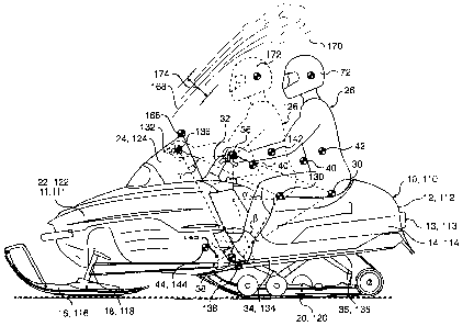
As shown in FIG. 2 and more clearly in FIG. 5, rider 126 is positioned on
snowmobile 110 so
that a line passing through seat position 130 and steering position 136 forms
an angle a with a line
passing through seat position 130 and footrest position 138. In addition, a
line passing through
footrest position 138 and steering position 136 forms an angle (3 with a line
passing through footrest
position 138 and seat position 130. Finally, a line passing through footrest
position 138 and steering
position 136 forms an angle y with a line passing through steering position
136 and seat position 130.
In other words, steering position 136, footrest position 138 and seat position
130 form a triangle with
angles a, (3, and ~y that
CA 02485813 1999-12-23
11
each fall within certain preferred ranges. For example, it is preferred that
anglea lie v yin a
range of between about 63 and 152°, that angle (3 lie within a range of
between about 16 and
84°, and that y lie within a range of between about I 1 and 42°.
It is more preferred that angle
a lie within a range of between about 67 and 112°, that angle (3 lie
within a range of between
about 41 and 72°, and that y lie within a range of between about 22 and
45°. It is even mare
preferred that angle a lie within a range of between about 75 and 92°,
that angle (3 lie within a
range of between about 52 arid 67°, and that y lie within a range of
between about 30 and 41 °.
Finally, it is most preferred that angle a be about 83°, that angle (3
be about 64°, and that y be
about 33°. In addition, it is preferred that angles a, (3, and y be
selected so that a >_ p >_ y.
Moreover, it is preferred that the angles be selected to satisfy the following
equation: a ~ 2.5y.
FIGS. 15-18 illustrate the ranges within which seat position 130 and steering
position
136 may be varied while remaining within the scope of the present invention.
The cross-
hatched regions indicate the range within which steering position I36 and seat
position 130
may fall depending upon the design of snowmobile I 10 anal the size and shape
of rider 126.
When angles a, (3, and y satisfy any of the relationships set forth above, and
preferably when steering position 136 is positioned forward of a vertical line
passing through
the vehicle's center of gravity 144, the rider's center of gravity 140 is
positioned much closer
to the center of gravity of the vehicle 144 than for conventional snowmobile
10 (as illustrated
in FIG. 3). In additian, when rider 126 is positioned as illustrated in FIG.
2, the rider's feet
146 are more in line with his torso 142 and his center of gravity 140. This
position has a
number of advantages, as described in greater detail below.
When rider 26 is sitting on conventional snowmobile 10, if he sees a large
bump
ahead, it is natural for rider 26 to try to raise himself off of seat 28 to
minimize the impact of
the bump as he passes over it. However, because of his positioning on
conventional
snowmobile 10, in order for rider 26 to stand up, he must pull on steering
device 32 using his
upper body. The positioning of the rider's feet 46 forward of the rider's
center of gravity 40
and at an incline on footrests 34 makes it difficult fox rider 26 to stand on
snowmobile 10
using only the strength of his legs. Moreover, even after rider 26 lifts
himself from seat 28,
his center of gravity 40 remains sufficiently rearward of the center of
gravity of the vehicle 44
that he will perceive the large bump.
In snowmobile 110 of the present invention, however, a wholly different result
is
achieved. First, steering position 136 is displaced forward of the center of
gravity of the
vehicle 144. This position pulls rider 126 forward of the conventional
position. ~y moving
seat position 130 closer to the center of gravity of the vehicle 144 than the
conventional
example, and by redesigning foatrests 134 so that they are kept at a decline,
rider 126 is
positioned so that, if a large bump is seen in the path ahead, rider 126 can
easily raise himself
CA 02485813 1999-12-23
12
from the seat using primarily the strength of only his legs 152. Since rider
126 is ~ used
closer to the center of gravity of the vehicle 144, when snowmobile 110 passes
over a large
bump, the effect of the bump is not transferred to rider 126 with the same
magnitude as the
force transferred to rider 26 on conventional snowmobile 'l0.
In addition, because rider 126 can raise himself from seat 128 using his legs
152 and
not his arms 154, rider 126 can maintain greater control over snowmobile 110
as he passes
over the obstacle than rider 26 on conventional snowmobile 10. If rider 26
tries to pull
himself from seat 28 as he passes over a large bump or obstacle, he sacrifices
some of this
strength pulling himself up from seat 28 and, therefore, may be less able to
steer and control
the vehicle as he passes over the obstacle.
To facilitate the rider's ability to raise himself off of seat 128 using his
legs 152,
footrests 134 are not inclined as with snowmobile 10. Instead, footrests 134
are part of the
forward portion of the sideboards 135 that laterally extend from the frame
below the seat on
either side thereof. As a result, footrests 134 are at angle ~ with respect to
the horizontal.
Preferably, angle D is between about +10 and -20°. More preferably,
angle d lies between
about +10 and -10°. Even more preferably, angle D lies between about 0
and -5°. Most
preferably, angle ~ is about -5°.
As mentioned, one aspect of the present invention that improves upon the
conventional snowmobile i0 is the fact that the rider's center of gravity 140
is closer to the
center of gravity of the vehicle 144 than in the conventional example. This
positioning helps
to minimize the effect Qf bumps and terrain on rider l2fi. Refernng to FIGS. 2
and 6, it is
preferred that a distance x, measured as the distance between a vertical line
158 passing
through the center of gravity of the vehicle 144 and a vertical line 160
passing through the
center of gravity of the rider 140, be between about 0 and SO cm. It is more
preferred that
distance x be between about 10 and 40 crn. In still a more preferred example,
distance x is
between about 22 and 32 cm. In the most preferred exarnpie, distance x is
about 2S or 30 cm.
Also, a distance a between a vertical line passing through the center of
gravity of the
snowmobile without the rider 144' and a vertical line passing through the
center of gravity of
the snowmobile with the rider 144 is preferably between about 0 and 14 cm.
More preferably,
distance a is between about 2 and 12 cm. Still more preferably, distance a is
between about 4
and 10 cm. Still more preferably, distance a is between about 5 and 7 cm. Most
preferably,
distance a is about 5 cm.
Similarly, a distance z between a vertical line passing through the forward-
most drive
track axle 121 (usually, but not exclusively the drive axle) and a vertical
line passing through
the center of gravity of the rider 140 is preferably between about 15 and 65
cm. More
CA 02485813 1999-12-23
13
preferably, distance z is between about 25 and 55 cm. Still more preferably,
distal, z is
between about 35 and 55 cm. Still more preferably, distancez is between about
37 and 47 crn.
Most preferably, distance z is about 40 cm or about 45 cm.
In addition, a distance y between a vertical line passing through the center
of gravity
of the snowmobile without the rider 144' and a vertical line passing through
the center of
gravity of the rider 140 is preferably between about 5 and 55 cm. More
preferably, distancey
is between about 15 and 45 cm. Still more preferably, distancey is between
about 25 and 45
cm or between about 27 and 37 em. Most preferably, distance y is about 30 or
35 cm.
Similarly, when rider 126 is positioned on snowmobile 110 so that his center
of
gravity 140 is closer to the center of gravity of the vehicle 144 than the
conventional example,
a line passing through the center of gravity of the vehicle 144 and the center
of gravity of the
rider 140 forms an angle A with horizontal 156 that preferably falls within a
range between
about 35 and 84°. More preferably, angle 0 lies between 45 and
75°. Still more preferably,
angle 8 lies within a range between about 55 and 70°. Finally, angle 8
is about 57°.
In this regard, snowmobile 110 has a center of gravity positioned so that a
line
passing through the forward-most drive track axle 121 and the center of
gravity of the rider
140 preferably forms an angle ac with horizontal that is between about 41 and
75°. More
preferably, angle ~s is between about 45 and 65°. Still more
preferably, angle ~ is between
about 50 and 60°. Most preferably, angle ~ is about 55°.
Snowmobile 110 has a center of gravity positioned so that a line passing
through the
center of gravity of the snowmobile without the rider 144' and the center of
gravity of the
snowmobile with the rider 144 preferably forms an angle; ?~ with horizontal
that is between
about 35 and 90°. More preferably, angle 7~ is between about 50 and
90°. Still more
preferably, angle ~, is between about 62 and 90°. Most pret:erably,
angle ~, is about 67°.
Snowmobile 110 has a center of gravity positioned so that a line passing
through the
center of gravity of the snowmobile without the rider 144' and the center of
gravity of the
rider 140 preferably forms an angle co with horizontal that ins between about
39 and 79°. More
preferably, angle w is between about 49 and 69°. Still more preferably,
angle co is between
about 54 and 64°. Most preferably, angle w is about 59°.
In addition, when rider 126 is positioned on snowmobile 110 so that his center
of
gravity 140 is closer to the center of gravity of the vehicle 144 than in
conventional
snowmobile 10, a distance b between a vertical line passing through steering
position 136 and
a vertical line passing through seat position 130 is between about 40 and 90
cm. Preferably,
distance b is between about 60 and 80 cm. Most preferably, distance b {in FIG.
2} is either 65
or 70 cm.
CA 02485813 1999-12-23
~a
Furthermore, as shown in FIG. 11, with the steering position 136 and seat 1.
_cion
130 located so that the center of gravity of the rider 140 is closer to the
center of gravity of the
vehicle 144 than the conventional example, a line passing through steering
position 136 and
seat position 130 forms an angle ~ with horizontal lSb that lies in a range
between about 1S
and 51 °. More preferably, angle ~ lies in a range between about 19 and
41 °. Even more
preferably, angle ~ lies in a range between about 23 and 31 °. Most
preferably, angle ~ is
about 26°.
To improve the steerability of snowmobile 110, the inventors also altered the
positioning of the axis of the steering shaft 162 so that it is more steeply
sloped than the
steering shaft in prior art snowmobiles having a steering shaft over the
engine. With a steeper
slope to the axis of the steering shaft 162, the turning force applied by
rider 126 is more
directly applied to steer the vehicle. According to the present invention, and
as illustrated in
FIGS. 2 and 14, the axis of the steering shaft 162 forms an angle s with
vertical 164 that is
less than 45°. More preferably, angle a lies between about 2S and
40°. Even more preferably,
angle s lies between about 30 and 35°. Most preferably, angle E is
about 33°. The angular
position of the steering shaft 162 is also preferred because it facilitates
placement of steering
position 136 in a position forward of that for conventional snowmobile 10.
Positioning rider 126 on snowmobile 110 in the manner described has still
further
advantages. Windshield 124 has a top 166. When snowmobile 110 is moving, top
166 of
windshield 166 defines a point from which the air travels along a travel path
168. The air
along air travel path will have laminar flow characteristics until it reaches
a turbulent flow
region 170. When rider 126 is positioned tin snowmobile i 10 as described
above, the rider's
head I72 falls within the laminar flow region 174. As a result, rider 126
enjoys a more
comfortable ride because the air has a less adverse effect on his head 172 in
terms of
temperature, noise, etc.
Those skilled in the art will readily recognize that the positioning of the
rider's head
172 on snowmobile 110 is very different than that for conventional snowmobile
10. As
illustrated in FIG. 3, head 72 of zider 26 falls into the turbulent flow
region 170. Accordingly,
rider 26 experiences a poorer qualify ride than rider 126.
'The positioning of rider 12b on snowmobile 1 I0 in the manner taught by the
present
invention offers still further advantages. As illustrateal, the view that
rider 126 has of the
ground in front of him is much improved over the view of the ground in front
of rider 26 on
conventional snowmobile 26. This is true because rider 126 has less of the
snowmobile
fairings I22 and windshield 124 in front of him than rider 26 does. As a
result, rider 126 is
better able to react to obstacles in his immediate path than rider 26.
CA 02485813 1999-12-23
The height of the windshield 124, the location of seat position 130 and the
location of steering position
136 define a relationship that facilitates construction of a snowmobile 110
where the view of the rider
is improved. Specifically, a line between the top 166 of windshield 124 and
seat position 130 forms
an angle p with a line between steering position 136 and seat position 130
that lies between about 0
and 20°. Preferably, angle p lies between about 10 and 20°. Most
preferably, angle p, is about 18°.
The design of snowmobile 110 offers still further advantages. For example, as
illustrated in
FIG. 1, the rider's knees 48 are positioned very close to steering position
36. As a result, when rider
26 steers snowmobile 10, it is not uncommon for rider 26 to hits hip, knees 48
with steering device 32.
This presents a minor design diff culty that the present invention solves.
As shown in FIG. 4, when rider 126 turns steering device 132 to its maximum
positions, the
handlebars sweep out a handlebar space 176. Because steering device 132 is
positioned forward of the
center of gravity of the vehicle 144, handlebar space 176 cannot intersect
with the space occupied by
rider 126. In other words, rider 126 will not normally hit his knees 148 with
steering device 132 while
riding snowmobile 110.
Snowmobile 110 of the present invention also differs from conventional
snowmobile 10 in
that the steering device 132 is disposed forward of the axis of the forward-
most drive axle, which
corresponds closely to the center of gravity of the vehicle 144. Steering
device 132 is also positioned
forward of footrest position 138, which also differs from conventional
snowmobile 10. With steering
position 136 disposed forward of both the center of gravity of the vehicle 144
and forward of the
footrest position 138, the center of gravity of the rider 140 is positioned
much closer to the center of
gravity of the vehicle 144 than in conventional snowmobile 10.
The present invention offers still further advantages over the design of
conventional
snowmobile 10. Since rider 126 is positioned closer to the center of gravity
of the vehicle 144, the
ride for a second rider on the same vehicle is also improved because the
second occupant is also
disposed closer to the center of gravity of the vehicle. FIG. 3 is
illustrative.
Rider 26 (who is shown astride conventional snowmobile 10) is essentially in
the second
passenger seat for snowmobile 110. Since rider 126 has been moved forward, the
second ridex is
subject to the kind of forces that he would be subjected to if he were driving
a conventional
snowmobile 10. In other words, the second rider is no worse off than he would
be if he were
passenger 26 on conventional snowmobile 10. Indeed the second rider's
situation is quite improved,
and may approach that of a rider 26 on a conventional snowmobile 10.
In addition, since second rider experiences a similar ride experience to what
rider 26
experiences on conventional snowmobile, it is possible that a third. rider
could be added to snowmobile
110 behind the second rider. The third rider, then, would experience the
forces similar to those that a
second rider would normally experience on conventional snowmobile 10.
CA 02485813 2005-04-15
16
While the invention has been described with reference to several preferred
embodiments, it
will be understood by those skilled in the art that various changes may be
made and equivalents may
be substituted for elements thereof without departing from the spirit and
scope ofthe present
invention, In addition, many modifications may be made to adapt a particular
situation, component, or
material to the teachings ofthe present invention without departing from its
teachings as claimed.