Sélection de la langue

Search

Sommaire du brevet 2363603 

Énoncé de désistement de responsabilité concernant l'information provenant de tiers

Une partie des informations de ce site Web a été fournie par des sources externes. Le gouvernement du Canada n'assume aucune responsabilité concernant la précision, l'actualité ou la fiabilité des informations fournies par les sources externes. Les utilisateurs qui désirent employer cette information devraient consulter directement la source des informations. Le contenu fourni par les sources externes n'est pas assujetti aux exigences sur les langues officielles, la protection des renseignements personnels et l'accessibilité.

Disponibilité de l'Abrégé et des Revendications

L'apparition de différences dans le texte et l'image des Revendications et de l'Abrégé dépend du moment auquel le document est publié. Les textes des Revendications et de l'Abrégé sont affichés :

  • lorsque la demande peut être examinée par le public;
  • lorsque le brevet est émis (délivrance).
(12) Brevet: (11) CA 2363603
(54) Titre français: CAVITE RESONANTE MODIFIEE A CHARGE DE CONDUCTEURS A CARACTERISTIQUES ANTIPARASITES AMELIOREES
(54) Titre anglais: MODIFIED CONDUCTOR LOADED CAVITY RESONATOR WITH IMPROVED SPURIOUS PERFORMANCE
Statut: Réputé périmé
Données bibliographiques
(51) Classification internationale des brevets (CIB):
  • H01P 7/06 (2006.01)
  • H01P 1/207 (2006.01)
  • H01P 1/208 (2006.01)
(72) Inventeurs :
  • MANSOUR, RAAFAT R. (Canada)
(73) Titulaires :
  • COM DEV LTD. (Canada)
(71) Demandeurs :
  • COM DEV LTD. (Canada)
(74) Agent: SCHNURR, DARYL W.
(74) Co-agent:
(45) Délivré: 2004-05-11
(22) Date de dépôt: 2001-12-11
(41) Mise à la disponibilité du public: 2002-02-27
Requête d'examen: 2001-12-11
Licence disponible: S.O.
(25) Langue des documents déposés: Anglais

Traité de coopération en matière de brevets (PCT): Non

(30) Données de priorité de la demande:
Numéro de la demande Pays / territoire Date
60/254,109 Etats-Unis d'Amérique 2000-12-12

Abrégés

Abrégé anglais


ABSTRACT OF THE DISCLOSURE
A microwave cavity has a cut resonator therein that is conductor-
loaded. Filters made from one or more cavities having cut resonators
therein have improved spurious performance over previous filters. A filter
can have two conductor loaded resonators in one cavity or a combination
of conductor loaded resonators and dielectric resonators in different
cavities.

Revendications

Note : Les revendications sont présentées dans la langue officielle dans laquelle elles ont été soumises.


The embodiments of the invention in which an exclusive property
or privilege is claimed are defined as follows:
1. A bandpass filter comprising at least one cavity with said at
least one cavity having a cut resonator therein, said cut resonator
being part of a circle, said cavity having at least one wall, said
resonator being a conductor-loaded resonator and said resonator
being out of contact with said at least one wall.

2. A filter as claimed in Claim 1 wherein said cavity has a half
cut resonator located therein.

3. A filter as claimed in Claim 1 wherein the cavity has a
rectangular shape and said resonator is planar mounted.

4. A filter as claimed in Claim 3 wherein said resonator has a
modified shape.

5. A filter as claimed in Claim 4 wherein said modified shape
has at least one cut away portion.

6. A filter as claimed in Claim 4 where said modified shape
has at least a first cut away portion and a second cut away portion.

7. A filter as claimed in Claim 4 wherein said resonator has a
semicircular shape with one straight edge and a first cut away
portion having a rectangular shape and being substantially centrally
located in said straight edge.

8. A filter as claimed in Claim 7 wherein said resonator has a
substantially arcuate edge and second cut away portion having a
rectangular shape that is substantially centrally located in said
arcuate edge.

9. A filter as claimed in Claim 8 wherein said resonator
wherein said second cut away portion is larger than said first cut
away portion.

10. A filter as claimed in Claim 4 wherein the modified shape
of said resonator is cut away portions in specific areas to improve
spurious performance.

11. A filter as claimed in Claim 2 wherein said resonator is
made from superconductive material.


12. A filter as claimed in Claim 2 wherein said conductor-
loaded resonator is used in combination with at least one dielectric
resonator.

13. A filter as claimed in Claim 2 wherein said filter has at least
two cavities, there being a conductor-loaded resonator in one of
said at least two cavities and a dielectric resonator in the other of
said at least two cavities.

14. A filter as claimed in Claim 4 wherein there are at least two
conductor-loaded resonators located in said at least one cavity to
create a dual mode conductor-loaded cavity resonator with
improved spurious performance.

15. A filter as claimed in Claim 12 wherein said filter has eight
cavities, a first cavity and a last cavity containing conductor loaded
resonators and the remaining cavities containing dielectric
resonators.

16. A filter as claimed in Claim 12 wherein said filter has eight
cavities, a first, second and third cavity each containing a
conductor-loaded resonator and the remaining cavities containing
dielectric resonators.

17. A filter as claimed in Claim 2 wherein said half cut
resonator has a mode selected from the group of a single mode and
a dual mode.

18. A filter as claimed in Claim 2 wherein said conductor-
loaded resonator is made from a material selected from the group
of metallic, superconductive, thick film superconductive and single
crystal.

19. A filter as claimed in Claim 2 wherein said resonator is
made from copper.

20. A microwave cavity having at least one wall, said cavity
comprising a cut resonator located therein, said cut resonator being
part of a circle, said resonator being out of contact with said at least
one wall and said resonator being a conductor-loaded resonator.

21. A cavity as claimed in Claim 20 wherein said cavity has a
half cut resonator located therein.


22. A cavity as claimed in Claim 20 wherein said cavity has a
rectangular shape and said resonator is planar or mounted.

23. A cavity as claimed in Claim 22 wherein said resonator has
a modified shape.

24. A cavity as claimed in Claim 23 wherein said modified
shape has at least one cut away portion.

25. A cavity as claimed in Claim 23 wherein said modified
shape has at least a first cut away portion and a second cut away
portion.

26. A cavity as claimed in Claim 23 wherein said resonator has
a semicircular shape with one straight edge and a first cutaway
portion having a rectangular shape and being substantially centrally
located in said straight edge.

27. A cavity as claimed in Claim 23 wherein said resonator has
a substantially arcuate edge and a second cut away portion having a
rectangular shape that is substantially centrally located in said
arcuate edge.

28. A cavity as claimed in Claim 26 wherein said resonator has
an arcuate edge and a second cut away portion having a rectangular
shape that is substantially centrally located in said arcuate edge.

29. A cavity as claimed in Claim 22 wherein said resonator is
made from metal.

30. A cavity as claimed in Claim 23 wherein the modified
shape of said resonator are cut away portions in specific areas to
improve spurious performance.

31. A cavity as claimed in Claim 21 wherein said resonator is
made from superconductive material.

32. A cavity as claimed in Claim 21 wherein said conductor
loaded resonator is used in combination with at least one dielectric
resonator.

33. A cavity as claimed in Claim 23 wherein there are at least
two single mode conductor loaded resonators located in said cavity
to create a dual mode conductor-loaded cavity resonator with
improved spurious performance.


34. A cavity as claimed in Claim 21 wherein said conductor
loaded resonator is made from a material selected from the group
of metallic, superconductive, thick film superconductive and single
crystal.

35. A cavity as claimed in Claim 21 wherein said resonator is
made from copper.

36. A cavity as claimed in Claim 33 wherein said at least two
single mode conductor loaded resonators are a half cut resonator
and a quarter cut resonator.

37. A method of improving the spurious performance of a
bandpass filter, said method comprising locating a cut resonator in
at least one cavity of said filter, said cut resonator being part of a
circle, said cavity having at least one wall and said resonator being
located out of contact with said at least one wall, said resonator
having a cut-away portion.

38. A method of improving the spurious performance of a
bandpass filter said method comprising locating a conductor-
loaded cut resonator in at least one cavity of said filter, said cavity
having at least one wall and said resonator being located out of
contact with said at least one wall.

Description

Note : Les descriptions sont présentées dans la langue officielle dans laquelle elles ont été soumises.


CA 02363603 2001-12-11
MODIFIED CONDUCTOR LOADED CAVITY RESONATOR WITH
IMPROVED SPURIOUS PERFORMANCE
The present invention is related to microwave bandpass filters and
5 more particularly to the realization of compact size conductor-loaded cavity
filters for use in space, wireless applications and other applications where
size and spurious performance of the bandpass filters are critical.
Microwave filters are key components of any communication
systems. Such a system, be it wireless or satellite, requires filters to
10 separate the signals received into channels for amplification and
processing. The phenomenal growth in telecommunication industry in
recent years has brought significant advances in filter technology as new
communication systems emerged demanding equipment miniaturization
while requiring more stringent filter characteristics. Over the past decade,
15 the dielectric resonator technology has been the technology of choice for
passive microwave filters for wireless and satellite applications.
Figure 1 illustrates the traditional dual-mode conductor-loaded
cavity resonator. The resonator 1 is mounted in a planar configuration
inside a rectangular cavity 2. Table 1 provides the resonant frequency of
20 the first three resonant modes.
Table 1 Resonant frequency of prior art dual-mode conductor loaded cavity
resonators
Metal puck: (0.222" x 2.4" dia),Rectangular cavity: (1.9" x 3.2" x 3.2")
25 C_'vlindrical cavity: 1.9" x 'i.2" dia
Resonant Frequency Resonant Frequency


Mode Rectangular Cylindrical Cavity
Cavity


Mode 1 1.889 GHz l .940 GHz


Mode 2 ~ 2.506 GHz 2.733 GHz


Mode 3 3.434 GHz 3.322 GHz


SUMMARY OF THE INVENTION
It is an object of the present invention to provide a novel
configuration etc. both single mode and dual mode dielectric resonator
3o filters have been employed for such applications. It is a further object of
the present invention to provide a conductor-loaded cavity resonator filter
-1-

CA 02363603 2001-12-11
that can be used in conventional and cryogenic applications. I is still
another object of the present invention to provide a filter that is compact in
size with a remarkable loss spurious performance compared to previous
filters.
5 A microwave cavity has at least one wall. The cavity has a cut
resonator located therein, the resonator being out of contact with the at
least one wall.
A bandpass filter has at least one cavity. The at least one cavity
has a cut resonator therein. The cavity has at least one wall and the
1o resonator is out of contact with the at least one wall.
A method of improving the spurious performance of a bandpass
filter, the method comprising a cut resonator in at least one cavity of the
filter, the cavity having at least one wall and the resonator being located
out of contact with the at least one wall.
15 In tlhe drawings:
Figure 1 is a perspective view of a prior art dual mode conductor-
loaded cavity resonator where the resonator is mounted inside a metallic
enclosure;
Figure 2 is a perspective view of a half cut resonator contained
2o within a cavity;
Figure 3 is a perspective view of a modified half cut resonator
contained within a cavity;
Figure 4 is a top view of a shaped resonator;
Figure 5 is a top view of a two pole filter containing shaped
25 resonators;
Figure 6 is a graph showing the measured isolation results of the
filter described in 1~igure 5;
Figure 7 is a schematic top view of an 8-pole filter having
conductor-loaded resonators in two cavities and dielectric resonators in the
30 remaining cavity;
Figure 8 is a schematic top view of an 8-pole filter having
-2-

CA 02363603 2001-12-11
conductor-loaded resonators in three cavities and dielectric resonators in
the remaining cavities;
Figure 9 is a schematic top view of a dual-mode filter having two
conductor loaded resonators in each cavity.
5 The resonator of Figure 1 is a metallic resonator and the cavity 2 is
a metallic enclosure. The electric field of the first mode resembles the
TEI, in cylindrical cavities. Thus, the use of a magnetic wall symmetry
will not change the,° field distribution and consequently the resonant
frequency.
1 o In Figure 2, there is shown a half cut resonator 3 mounted in a
cavity 4. It can be seen that the resonator 3 has a semicircular shape. The
resonator 3 is mounted on a support (not shown) and is out of contact with
walls of the cavity 4. The resonator 3 does not touch the walls of the
cavity 4. The cavity 4 has almost half the volume of the cavity 2 shown in
15 Figure 1. A dielectric support structure (not shown) is used in both
Figures 1 and 2 to support the resonator.
With the use of the magnetic wall symmetry concept, a half cut
version of the conductor-loaded resonator with a modified shape can be
realized as shown i n Figure 3. The half cut resonator would have a slightly
2o higher resonant frequency with a size that is 50% of the original dual
mode cavity. The technique proposed in Wang et al "Dual mode
conductor-loaded cavity filters" I. EEE Transactions on Microwave
Theory and Techniques, V45, N. 8, 1997 can be applied for shaping
dielectric resonators to conductor-loaded cavity resonators. In Figure 4,
25 there is shown a top view of the modified half cut resonator of Figure 3.
The original half-cut resonator described in Figure 2 is selectively
machined to enhance the separation between the resonant frequencies of
the dominant and t:he first higher-order mode. It can be seen that a
substantially rectangular cutaway portion exists in a straight edge of the
30 resonator 5 and a larger rectangular shaped cut away portion is located in
the arcuate edge of the resonator 5. Both of the cut away portions are
-3-

CA 02363603 2001-12-11
substantially centrally located.
Table 2 provides the resonant frequencies of the first three modes
of the half cut conductor-loaded resonator. Even though the TM mode has
been shifted away, the spurious performance of the resonator has
5 degraded.
Table 2 The resonant frequencies of the first three modes
of the half cut conductor-loaded resonator
Mode Resonant Frequency


Mode 1 2.119 GHz


Mode 2 2.234 GHz


Mode 3 3.824 GHz


Table 3 gives the resonant frequencies of the first three modes of
l0 the modified half=cut resonator. A comparison between Tables 2 and 3
illustrates that the spurious performance of the modified half cut resonator
is superior to that of dual-mode resonators. It is interesting to note that
shaping the resonator as shown in Figure 3 has shifted Mode 1 down in
frequency while shifting Mode 2 up in frequency. This translates to a size
15 reduction and a significant improvement in spurious performance.
Table 3. The resonant frequencies of the first three modes of the
modified half cut conductor-loaded resonator
Mode Resonate Frequency


Mode 1 1.559 GHz


Mode 2 2.980 GHz


Mode 3 3.535 GHz


20
It is well known that dielectric resonators filters suffer from
limitations in spurious performance and power handling capability. By
combining the dielectric resonators with the resonator disclosed in this
-4-

CA 02363603 2001-12-11
invention both the spurious performance and power handling capability of
dielectric resonator filters can be considerably improved.
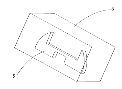
Figure 4 shows a resonator 5 mounted inside an enclosure 6. The
resonator 5 is a modified version of the resonator 3 shown in Figure 2 where
5 a metal is machined out in specific areas to improve the spurious
performance of the resonator. Figure 4 is an actual picture of the resonator 5
in the open cavity fi.
Figure 5 shows a picture of a two pole filter built using the resonator
5. The filter consisla of two resonators coupled by an iris (not shown).
Figure
10 6 shows the experimental isolation results of the filter shown in Figure 5.
The
results demonstrate the improvement in spurious performance. The spurious
area is located at a~>proximately twice the filter centre frequency.
Figure 7 shows an eight-pole filter where six dielectric resonators 6
are used in six cavities 7 in combination with two half cut metallic
resonators
15 5 in two cavities 7. The RF energy is coupled to the filter through
input/output probes. 8, 9 respectively. The metallic resonators could be
placed
horizontally as shown in Figure 7 or vertically. Even though the dielectric
resonator filters have a limited spurious performance, the addition of the two
metallic resonators considerably improves the overall spurious performance
20 of the filter. In Figure 7, the metallic resonators are placed in the first
and
last cavities. However, metallic resonators can be placed in any of the
cavities. .
Figure 8 shows an eight-pole filter where five dielectric resonators 6
are located in five cavities 7 in combination with three half cut metallic
25 resonators 5 located in three cavities 7. The RF energy is coupled to the
filter
through input/output probes 8, 9 respectively. The metallic resonators are
placed in the first three cavities to improve the power handling capability of
the dielectric resonator filter. It well known that, in high power
applications,
high electric field will build up in the first three cavities. Such high field
3o translates into heat, which in turn degrades the Q of the resonator, and
affects
the integrity of the support structure. The problem can be circumvented by
-5-

CA 02363603 2001-12-11
replacing the dielectric resonators in these cavities with metallic resonators
disclosed in this invention. In both Figure 7 and Figure 8, there is one
resonator in each cs~vity.
Figure 9 shows a four pole dual-mode filter consisting of two dual
mode resonators 10 in each cavity 7. Each dual-mode resonator is formed by
combining two single-mode resonators 5. The end result is a compact dual
mode resonator with an improved spurious performance.
A combination of dielectric resonators and conductor-loaded cavity
resonators in the same filter improves the spurious performance of dielectric
1 o resonator filters over dielectric resonator filters that do not have any
conductor-loaded cavity resonators. The use of conductor-loaded cavity
resonators in the same filter in combination with dielectric resonators extend
the power handling capability of dielectric resonator filters.
Various materials are suitable for the resonators. For example, the
resonator can be made of any metal or it can be made of superconductive
material either by a thick film coating or bulk superconductor materials or
single crystal or by other means. Copper is an example of a suitable metal.
-6-

Dessin représentatif
Une figure unique qui représente un dessin illustrant l'invention.
États administratifs

Pour une meilleure compréhension de l'état de la demande ou brevet qui figure sur cette page, la rubrique Mise en garde , et les descriptions de Brevet , États administratifs , Taxes périodiques et Historique des paiements devraient être consultées.

États administratifs

Titre Date
Date de délivrance prévu 2004-05-11
(22) Dépôt 2001-12-11
Requête d'examen 2001-12-11
(41) Mise à la disponibilité du public 2002-02-27
(45) Délivré 2004-05-11
Réputé périmé 2005-12-12

Historique d'abandonnement

Il n'y a pas d'historique d'abandonnement

Historique des paiements

Type de taxes Anniversaire Échéance Montant payé Date payée
Examen avancé 100,00 $ 2001-12-11
Requête d'examen 400,00 $ 2001-12-11
Enregistrement de documents 100,00 $ 2001-12-11
Le dépôt d'une demande de brevet 300,00 $ 2001-12-11
Enregistrement de documents 50,00 $ 2003-04-25
Taxe de maintien en état - Demande - nouvelle loi 2 2003-12-11 100,00 $ 2003-12-08
Taxe finale 300,00 $ 2004-02-26
Titulaires au dossier

Les titulaires actuels et antérieures au dossier sont affichés en ordre alphabétique.

Titulaires actuels au dossier
COM DEV LTD.
Titulaires antérieures au dossier
MANSOUR, RAAFAT R.
Les propriétaires antérieurs qui ne figurent pas dans la liste des « Propriétaires au dossier » apparaîtront dans d'autres documents au dossier.
Documents

Pour visionner les fichiers sélectionnés, entrer le code reCAPTCHA :


Pour visualiser une image, cliquer sur un lien dans la colonne description du document. Pour télécharger l'image (les images), cliquer l'une ou plusieurs cases à cocher dans la première colonne et ensuite cliquer sur le bouton "Télécharger sélection en format PDF (archive Zip)" ou le bouton "Télécharger sélection (en un fichier PDF fusionné)".

Liste des documents de brevet publiés et non publiés sur la BDBC .

Si vous avez des difficultés à accéder au contenu, veuillez communiquer avec le Centre de services à la clientèle au 1-866-997-1936, ou envoyer un courriel au Centre de service à la clientèle de l'OPIC.


Description du
Document 
Date
(yyyy-mm-dd) 
Nombre de pages   Taille de l'image (Ko) 
Description 2001-12-11 6 244
Abrégé 2001-12-11 1 10
Revendications 2001-12-11 4 142
Dessins 2001-12-11 9 211
Dessins représentatifs 2002-01-24 1 6
Revendications 2003-02-24 4 155
Revendications 2003-10-07 4 160
Page couverture 2002-02-22 1 31
Revendications 2002-07-13 4 147
Page couverture 2004-04-14 1 31
Poursuite-Amendment 2002-01-28 1 13
Poursuite-Amendment 2002-03-15 2 58
Correspondance 2002-03-20 1 11
Cession 2001-12-11 7 212
Poursuite-Amendment 2002-07-15 8 307
Poursuite-Amendment 2002-10-22 2 60
Poursuite-Amendment 2003-02-24 7 242
Poursuite-Amendment 2003-04-07 1 32
Cession 2003-04-25 20 879
Poursuite-Amendment 2003-10-07 6 194
Taxes 2003-12-08 1 31
Correspondance 2004-02-26 1 29