Sélection de la langue

Search

Sommaire du brevet 2078824 

Énoncé de désistement de responsabilité concernant l'information provenant de tiers

Une partie des informations de ce site Web a été fournie par des sources externes. Le gouvernement du Canada n'assume aucune responsabilité concernant la précision, l'actualité ou la fiabilité des informations fournies par les sources externes. Les utilisateurs qui désirent employer cette information devraient consulter directement la source des informations. Le contenu fourni par les sources externes n'est pas assujetti aux exigences sur les langues officielles, la protection des renseignements personnels et l'accessibilité.

Disponibilité de l'Abrégé et des Revendications

L'apparition de différences dans le texte et l'image des Revendications et de l'Abrégé dépend du moment auquel le document est publié. Les textes des Revendications et de l'Abrégé sont affichés :

  • lorsque la demande peut être examinée par le public;
  • lorsque le brevet est émis (délivrance).
(12) Brevet: (11) CA 2078824
(54) Titre français: TOUR AUXILIAIRE A HAUT RENDEMENT POUR PONT DE REPARATION
(54) Titre anglais: HEAVY DUTY AUXILIARY TOWER FOR A REPAIR RACK
Statut: Réputé périmé
Données bibliographiques
(51) Classification internationale des brevets (CIB):
  • B21D 1/14 (2006.01)
  • B21D 7/14 (2006.01)
(72) Inventeurs :
  • HAMILTON, HAROLD FRED (Etats-Unis d'Amérique)
(73) Titulaires :
  • HEIN-WERNER CORPORATION (Etats-Unis d'Amérique)
(71) Demandeurs :
(74) Agent: AVENTUM IP LAW LLP
(74) Co-agent:
(45) Délivré: 1996-10-29
(22) Date de dépôt: 1992-09-21
(41) Mise à la disponibilité du public: 1993-04-02
Requête d'examen: 1995-09-21
Licence disponible: S.O.
(25) Langue des documents déposés: Anglais

Traité de coopération en matière de brevets (PCT): Non

(30) Données de priorité de la demande:
Numéro de la demande Pays / territoire Date
07/769,864 Etats-Unis d'Amérique 1991-10-01

Abrégés

Abrégé anglais


An anchor force assembly mounted on a repair
rack or on the floor in a spaced relation to a pull tower
having a chain for applying a tensile force to the
damaged vehicle, the anchor force assembly including a
base plate assembly which is adapted to be mounted on the
edge of the top of the rack, or on the floor, the base
plate assembly including a base plate having a clamp
mounted on each end, a pair of spacer blocks mounted on
the base plate and a tower assembly pivotally mounted on
said base plate assembly, the tower assembly including a
pivot plate pivotally secured to the plate assembly, a
tubular vertical member mounted on said plate, a tubular
horizontal member mounted on said plate with one end
abutting the vertical member and a tubular gusset mounted
between said horizontal and vertical member whereby the
chain can be attached to the vehicle with the end of the
chain attached to the auxiliary tower whereby the force
generated by the pull tower is doubled.

Revendications

Note : Les revendications sont présentées dans la langue officielle dans laquelle elles ont été soumises.


-7-

The embodiments of the invention in which an
exclusive property or privilege is claimed are defined as
follows:

1. In an apparatus for repairing and
straightening vehicles including a rack having upper
and lower tracks, a plurality of pull towers
mounted on said lower tracks for movement around the
rack, each pull tower including a tension member
having a free end for attachment to the damaged area
of the vehicle, the improvement comprising an
auxiliary tower mounted on said upper track in close
proximity to one of the pull towers whereby said
tension member can be attached to said vehicle with
said free end of said tension member attached to
said auxiliary tower whereby a tensile force applied
to the chain will be doubled at the point of
connection of the chain to the damaged vehicle.

2. The auxiliary tower according to claim 1
wherein said auxiliary tower includes a tower assembly
and a cap plate assembly, said cap plate assembly being
mounted on the upper track, said tower assembly includes
a base plate, a horizontal member mounted on said base
plate and extending inwardly on the rack, a vertical
member secured to said base plate at the outer end of
said horizontal member and a gusset member positioned
between said horizontal member and said vertical member
whereby said vertical member is prevented from movement
with respect to said horizontal member on application of
a pull force on the tension member.

3. The auxiliary tower according to claim 2
wherein said cap plate assembly includes a cap plate, a
pair of spacer bars mounted on said cap plate for


-8-

separating said tower assembly from said cap plate a
distance equal to the thickness of said upper track.

4. The apparatus according to claim 3
including a clamp mounted on each end of said cap plate
for securing said cap plate assembly to said upper track.

5. The apparatus according to claim 4
including means on said vertical member for supporting
said tension member at predetermined heights.

6. An anchor force assembly arranged to be
mounted on a rack or floor in a spaced relation to a
pull tower for doubling the force applied to a
vehicle to be repaired, said assembly comprising a
base plate assembly including a base plate, a pair
of lugs mounted on each end of said base plate and a
pair of spacer blocks mounted on said plate, and a
tower assembly pivotally mounted on said base plate
assembly, said tower assembly including a plate
pivotally secured to said plate assembly, a tubular
vertical member mounted on said plate and a tubular
gusset mounted between said tubular member and said
plate.

7. The combination with one or more pull
towers mounted around the perimeter of a damaged
vehicle, each pull tower including a chain having a
free end for attachment to the damaged area of a
vehicle, of one or more auxiliary towers for
repairing damaged vehicles, each of said auxiliary
towers comprising:
a tower assembly including a base plate,
a horizontal member mounted on said base plate
and extending inwardly toward the vehicle,


-9-

a vertical member secured to said plate at the
outer end of said horizontal member,
a gusset member positioned between said
horizontal member and said vertical member, and
means for supporting said tower assembly for
pivotal movement with respect to the damaged
vehicle.

8. The combination according to claim 7
including an auxiliary plate mounted in a spaced relation
to the floor, said supporting means comprising a cap
plate assembly including a pair of clamps for engaging
said auxiliary plate.
Description

Note : Les descriptions sont présentées dans la langue officielle dans laquelle elles ont été soumises.


20788~4


HEAVY DUTY AUYTT-T~Y TOWER FOR A REPAIR RAC~

FIT~'T~n OF THT~` INVT~'~TIO~
The present invention relates to frame
straightening equipment wherein a damaged vehicle is
supported on a rack or floor, and a number of pulling
towers are provided around the vehicle to apply forces to
the damaged areas of the vehicle and more particularly to
a heavy duty auxiliary tower which can be selectively
mounted on the rack or floor, and coupled to one of the
pulling towers to double the pulling force of the tower.

BACKGROU~D OF THF~' INVT~TIO~
Collision repair of the type contemplated
herein generally includes a rack or floor system, on
which a vehicle is anchored and a plurality of pulling
towers which are mounted on the rack or anchored to the
floor for applying a tensile or pulling force on the
damaged area of the vehicle. The towers are generally
freely movable about the perimeter of the vehicle for
easy alignment with the damaged area of the vehicle. A
chain is provided on the tower which can be adjusted to
any height and is attached directly to the damaged part
of the vehicle. A hydraulic force is applied to the
chain which is used to pull the damaged area back to its

~7~24


original shape. When heavy pulls are required a second
pulling tower is moved in close proximity to the first
tower in order to obtain a sufficient force to return the
damaged area to its original shape.
SUMMARY OF THE PRESENT INVENTION
The heavy duty auxiliary tower according to the
present invention includes a base plate assembly which is
simply and easily attached to the rack or floor, and an
auxiliary tower assembly pivotally mounted on the base
plate assembly. The chain on the pulling tower is passed
through a snap block and hook assembly and connected to
the auxiliary tower. The block and hook assembly is
connected to the damaged area of the vehicle. The base
plate assembly is positioned so that the chain is aligned
at the same level as the snap block assembly. On
application of a force on the chain a double force is
achieved which increases the pulling force of the tower
from a normal 5,000 lb. pull to a 10,000 lb. pull.
One of the primary advantages of the heavy duty
auxiliary tower is the ability to simply and easily mount
the auxiliary tower at any point around the vehicle.
A further advantage of the heavy duty auxiliary
tower is the ability to change the angle of correction or
pull by aligning the auxiliary tower assembly in the
direction of the pulling force to thereby equalize the
force on the damaged vehicle.
Another advantage of the auxiliary tower is the
ability to be used as a nonpull tower or anchoring
device.
Other principal features and advantages of the
invention will become apparent to those skilled in the
art upon review of the following drawings, the detailed
description and the appended claims.

2078~24


BRIEF DESCRIPTION OF THE DRAWINGS
Figure 1 is a perspective view of a repair rack
of the type contemplated herein.
Figure 2 is a side view of the rack showing the
auxiliary tower according to the invention mounted on the
rack and connected to a pulling tower.
Figure 3 is a top view of the auxiliary tower
shown mounted on the rack.
Figure 4 is an exploded perspective view of the
auxiliary tower.
Figure 5 is a view taken on line 5-5 of Figure
3.
Before explaining at least one emho~iment of
the invention in detail it i8 to be understood that the
invention is not limited in its application to the
details of construction and the arrangement of the
components set forth in the following description or
illustrated in the drawings. The invention is capable of
other embodiments or being practiced or carried out in
various ways. Also, it is to be understood that the
phraseology and terminology employed herein is for the
purposes of description and should not be regarded as
limiting.

DETAI~n DESCRIPTION OF THE PREFERRED EMBODIMENTS
As shown in the drawings a rack 10 of the type
contemplated herein generally includes an upper plate 14
for supporting a vehicle and defining an upper track 16
around the outer perimeter of the rack. A lower plate 18
is spaced beneath the upper plate by a web 15. The lower
plate 18 defines a lower track 19 around the perimeter of
the rack. The rack is su~o~ed on the floor by legs 20.
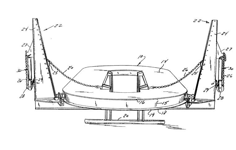
A number of pulling towers 22 are mounted on
the lower track 19 which are free to move about the
perimeter of the lower track 19 to any desired location.
Each tower includes a vertical member 24 having (a chain

20788~4


26 wrapped around) an adjustable pocket wheel 25 located
on the front of the tower and guide roller 29 at the back
of the tower. A pocket wheel 28 is mounted on a
hydraulic piston and cylinder assembly 30 provided on the
back of the tower. A chain 26 is wrapped around pocket
wheel 28, guide roller 29 and pocket wheel 28. One end
of the chain 26 is secured to a bracket 27 located at the
back of the tower. The other end of the chain 26 is
connected to the damaged part. A tensile force is
applied to the chain 26 by extending the piston in
assembly 30.
In accordance with the present invention the
heavy duty auxiliary tower 12 as shown in Figure 2 is
secured to the upper track 16 on rack 10. The chain 26
is passed through a snap block 32 and connected to the
auxiliary tower 12. A hook 34 in snap block 32 is
connected to the damaged area of the vehicle.
The auxiliary tower 12 generally includes a
tower assembly 35 and a cap plate assembly 50. The tower
assembly 35 includes a base plate 40 having a horizontal
tube 36 and a vertical tube 38 mounted thereon. A spacer
bar 37 having a plurality of recesses 39 is mounted on
the back of vertical tube 38. A flat plate 42 is
provided at the end of the horizontal tube 36 with an ear
plate 44 provided on each side of the horizontal tube. A
tubular gusset 48 is provided between the horizontal tube
36 and the vertical tube 38. The tower assembly 35 is
secured to the upper track 16 of the rack by means of the
cap plate assembly 50.
In this regard, the assembly 50 includes a cap
plate 52 having a lug plate 54 mounted on each end. Each
lug plate includes an upper arm 56 and a lower arm 58.
The lower arm 58 is aligned with the upper surface of the
cap plate 52. The upper arm 56 is spaced from the lower
arm 58 a distance slightly greater than the thickness of
upper plate 14 on the rack 10. A pair of spacer plates

2Q78~2~


60 are provided on the upper surface of the cap plate 52
to space the tower assembly 35 from the cap plate
assembly 50 a distance equal to the thickness of the
plate 14.
The cap plate assembly 50 is secured to the
tower assembly 35 by means of a bolt 62 which is
positioned in a hole 64 provided in the base plate 40 and
a hole 66 provided in the cap plate 52. The bolt 62 is
locked in position by lock nuts 68 with the base plate 40
seated on the spacer plates 60. It should be noted that
the spacer plate 60 has a thickness substantially equal
to the thickness of the upper plate 14 on the rack. The
cap plate assembly 50 is mounted on the upper track 16 by
aligning the upper track 16 in the space between the
upper leg 56 and lower leg 58 of the lug plates 54.
Bolts 70 are provided in the upper legs 56 for securing
the cap plate assembly 50 to the upper track on the rack.
The tower assembly 35 can be pivoted about the bolt 62 to
align the horizontal tube 36 with the point of connection
of the chain to the snap block 34. As shown in Figure 2
the chain 26 can be attached to and retained at various
elevations with respect to the vertical tube 38 by
wrapping the chain through one of the recesses 39 in the
spacer plate 37 provided on the back of the vertical tube
38.
In operation once the auxiliary tower has been
mounted on the rack 10, the chain 26 is wrapped around a
pocket wheel 64 in the snap block assembly with the end
of the chain secured to the vertical tube 38 on the
auxiliary tower. On application of a tensile force to
the chain 26, the hook 34 on the snap block will exert a
force to the damaged area that is double the force
applied by the hydraulic system on the pulling tower.
Although the auxiliary tower has been shown and
described in connection with a work rack, it should be
understood that the tower could also be mounted directly

2~7S~2~


--6--
on the floor. In this regard, standard type chain
anchors could be attached directly to the tower assembly
35 and to existing anchor pots provided in the floor. In
an alternate arrangement, an auxiliary plate is anchored
to the floor to support the auxiliary tower. The
auxiliary plate should be spaced a distance from the
floor sufficient for the cap plate assembly 50 to engage
the edge of the auxiliary plate.
Thus, it should be apparent that there has been
provided in accordance with the present invention a heavy
duty auxiliary tower for a repair rack that fully
satisfies the aims and advantages set forth above.
Although the invention has been described in conjunction
with specific embodiments thereof, it is evident that
many alternatives, modifications and variations will be
apparent to those skilled in the art. Accordingly, it is
intended to embrace all such alternatives, modifications
and variations that fall within the spirit and broad
scope of the appended claims.

Dessin représentatif
Une figure unique qui représente un dessin illustrant l'invention.
États administratifs

Pour une meilleure compréhension de l'état de la demande ou brevet qui figure sur cette page, la rubrique Mise en garde , et les descriptions de Brevet , États administratifs , Taxes périodiques et Historique des paiements devraient être consultées.

États administratifs

Titre Date
Date de délivrance prévu 1996-10-29
(22) Dépôt 1992-09-21
(41) Mise à la disponibilité du public 1993-04-02
Requête d'examen 1995-09-21
(45) Délivré 1996-10-29
Réputé périmé 2005-09-21

Historique d'abandonnement

Il n'y a pas d'historique d'abandonnement

Historique des paiements

Type de taxes Anniversaire Échéance Montant payé Date payée
Le dépôt d'une demande de brevet 0,00 $ 1992-09-21
Taxe de maintien en état - Demande - nouvelle loi 2 1994-09-21 100,00 $ 1994-08-04
Taxe de maintien en état - Demande - nouvelle loi 3 1995-09-21 100,00 $ 1995-06-28
Enregistrement de documents 0,00 $ 1996-02-22
Taxe de maintien en état - Demande - nouvelle loi 4 1996-09-23 100,00 $ 1996-06-26
Taxe de maintien en état - brevet - nouvelle loi 5 1997-09-22 150,00 $ 1997-09-16
Taxe de maintien en état - brevet - nouvelle loi 6 1998-09-21 150,00 $ 1998-08-04
Taxe de maintien en état - brevet - nouvelle loi 7 1999-09-21 150,00 $ 1999-08-09
Taxe de maintien en état - brevet - nouvelle loi 8 2000-09-21 150,00 $ 2000-09-05
Taxe de maintien en état - brevet - nouvelle loi 9 2001-09-21 150,00 $ 2001-08-31
Taxe de maintien en état - brevet - nouvelle loi 10 2002-09-23 200,00 $ 2002-09-03
Taxe de maintien en état - brevet - nouvelle loi 11 2003-09-22 200,00 $ 2003-09-03
Titulaires au dossier

Les titulaires actuels et antérieures au dossier sont affichés en ordre alphabétique.

Titulaires actuels au dossier
HEIN-WERNER CORPORATION
Titulaires antérieures au dossier
HAMILTON, HAROLD FRED
Les propriétaires antérieurs qui ne figurent pas dans la liste des « Propriétaires au dossier » apparaîtront dans d'autres documents au dossier.
Documents

Pour visionner les fichiers sélectionnés, entrer le code reCAPTCHA :


Pour visualiser une image, cliquer sur un lien dans la colonne description du document. Pour télécharger l'image (les images), cliquer l'une ou plusieurs cases à cocher dans la première colonne et ensuite cliquer sur le bouton "Télécharger sélection en format PDF (archive Zip)" ou le bouton "Télécharger sélection (en un fichier PDF fusionné)".

Liste des documents de brevet publiés et non publiés sur la BDBC .

Si vous avez des difficultés à accéder au contenu, veuillez communiquer avec le Centre de services à la clientèle au 1-866-997-1936, ou envoyer un courriel au Centre de service à la clientèle de l'OPIC.


Description du
Document 
Date
(yyyy-mm-dd) 
Nombre de pages   Taille de l'image (Ko) 
Page couverture 1993-11-13 1 15
Abrégé 1993-11-13 1 26
Revendications 1993-11-13 3 91
Dessins 1993-11-13 3 86
Description 1993-11-13 6 221
Abrégé 1996-10-29 1 27
Page couverture 1996-10-29 1 14
Description 1996-10-29 6 234
Revendications 1996-10-29 3 94
Dessins 1996-10-29 3 91
Dessins représentatifs 1998-09-08 1 25
Correspondance 1999-12-07 1 14
Taxes 1998-08-25 1 54
Taxes 1997-10-08 2 66
Correspondance de la poursuite 1996-03-21 1 26
Correspondance de la poursuite 1992-09-21 1 45
Correspondance reliée au PCT 1993-03-31 2 86
Correspondance reliée au PCT 1993-03-23 4 135
Lettre du bureau 1995-11-08 1 33
Correspondance reliée au PCT 1996-08-22 1 37
Taxes 1997-09-29 1 28
Taxes 1996-10-27 1 43
Taxes 1996-10-17 1 19
Taxes 1996-06-26 1 36
Taxes 1995-06-28 1 36
Taxes 1994-08-04 1 39