Note: Descriptions are shown in the official language in which they were submitted.
SYSTEMS AND METHODS FOR CUSTOMIZING A PERFORMANCE
CHARACTERISTIC OF A VEHICLE
TECHNICAL FIELD
[0001] The disclosure relates generally to the operation of vehicles, and
more
particularly to customizing performance characteristics of vehicles.
BACKGROUND
[0002] Some vehicles provide a few selectable factory-defined
operational modes
for the vehicles such as economy mode, normal mode, or sport mode to provide
different
operator experiences with the vehicle. However, the factory-defined
operational modes
are associated with predefined and fixed settings that limit the operator
experiences to
only the few factory-defined operational modes available. Improvement is
desirable.
SUMMARY
[0003] In one aspect, the disclosure describes a method of operating
an electric
vehicle based on an operator-defined propulsive performance characteristic of
the electric
vehicle. The method comprises:
receiving, via an operator interface, a value of an individually-variable
parameter defining the propulsive performance characteristic of the electric
vehicle;
receiving a command for propelling the electric vehicle;
driving an electric motor of the electric vehicle to propel the electric
vehicle
based on the command; and
when the electric motor is being driven, regulating an output of the electric
motor based on the value of the individually-variable parameter.
[0004] The value may include a numerical value. The value may
include a relative
value.
[0005] The parameter may include an operator-defined operational
limit of the
electric vehicle. The parameter may be an operator-defined maximum speed of
the
electric vehicle. The parameter may be indicative of an operator-defined
maximum
acceleration of the electric vehicle. The parameter may be indicative of an
operator-
defined maximum output power of a powertrain of the electric vehicle. The
parameter
- 1 -
Date Recue/Date Received 2021-03-31
may be indicative of an operator-defined maximum output torque of the electric
motor.
The parameter may be indicative of an operator-defined maximum amount of
slippage
allowable between a ground-engaging member of the electric vehicle and a
ground.
[0006] The electric vehicle may be a snowmobile. The ground-engaging
member
may include a track of the snowmobile.
[0007] The parameter may be indicative of a difference between a
theoretical
speed of the electric vehicle determined from an operating speed of a
powertrain of the
electric vehicle, and an estimated actual speed of the electric vehicle. The
method may
include determining the estimated actual speed of the electric vehicle using a
satellite
navigation device.
[0008] The parameter may be two-dimensional. The value may include
two
coordinates. One of the coordinates may include an operating speed of the
electric motor.
One of the coordinates may include an actuation position of an accelerator of
the electric
vehicle. One of the coordinates may include an output torque of the electric
motor. One
of the coordinates may include an acceleration of the electric vehicle.
[0009] The parameter may be part of a throttle map associated with
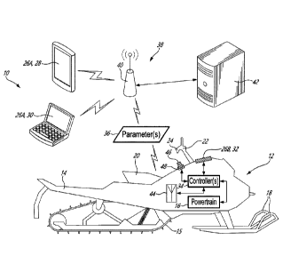
an
accelerator of the electric vehicle.
[0010] The value may include one or more points along a graph of a
relationship
between two variables. One of the two variables may include an output torque
of the
electric motor. One of the two variables may include an actuation position of
the
accelerator.
[0011] The parameter may be indicative of a throttle map associated
with an
accelerator of the electric vehicle.
[0012] The parameter may be indicative of a torque curve associated
with the
electric motor.
[0013] The parameter may be indicative of a regeneration behaviour
of the
electric vehicle.
- 2 -
Date Recue/Date Received 2021-03-31
[0014] The method may include: verifying whether the value of the
parameter is
within a predefined range; and when the value is outside the predefined range,
preventing
regulating the output of the electric motor based on the value of the
parameter.
[0015] The parameter may be a first individually-variable parameter.
The
predefined range may be variable based on a value of a second individually-
variable
parameter.
[0016] The value of the parameter may be associated with an operator
identification. The method may include verifying an identity of an operator
before
regulating the output of the electric vehicle based on the value of the
individually-variable
parameter.
[0017] Verifying the identity of the operator may include detecting
a portable
electronic device of the operator in proximity to the electric vehicle.
Verifying the identity
of the operator may include detecting a key associated with the operator.
[0018] The value of the individually-variable parameter may be a
first value of a
first individually-variable parameter. The method may include: receiving a
second value
of a second individually-variable parameter; and regulating the output of the
electric motor
based on the first and second values of the respective first and second
individually-
variable parameters.
[0019] The method may include receiving, via an operator interface,
a plurality of
values of respective individually-variable parameters, the individually-
variable
parameters including at least two of the following: an operator-defined
maximum speed
of the electric vehicle, an operator-defined maximum acceleration of the
electric vehicle,
an operator-defined maximum output torque from the electric motor, an operator-
defined
torque curve associated with the electric motor, and an operator-defined
maximum output
power from the electric motor; and regulating the output of the electric motor
based on
the plurality of values of the respective individually-variable parameters.
[0020] The electric vehicle may be a powersport vehicle.
[0021] Embodiments may include combinations of the above features.
- 3 -
Date Revue/Date Received 2021-03-31
[0022] In another aspect, the disclosure describes a computer
program product
for implementing an operation of an electric vehicle according to an operator-
defined
propulsive performance characteristic of the electric vehicle.
[0023] In another aspect, the disclosure describes a system for
customizing a
propulsive performance characteristic of an electric vehicle. The system
comprises:
an operator interface facilitating input of a value of an individually-
variable
parameter defining the propulsive performance characteristic of the electric
vehicle;
one or more data processors operatively connected to the operator
interface; and
non-transitory machine-readable memory storing instructions executable
by the one or more data processors and configured to cause the one or more
data
processors to:
cause an electric motor of the electric vehicle to be driven to propel the
electric vehicle; and
when the electric motor is being driven, cause an output of the electric
motor to be regulated based on the value of the individually-variable
parameter.
[0024] The value may include a numerical value. The value may
include a relative
value.
[0025] The parameter may be a slip ratio associated with a ground-
engaging
member of the electric vehicle. The ground-engaging member may include a track
of a
snowmobile.
[0026] The parameter may be two-dimensional. The value may include
two
coordinates.
[0027] The value may include one or more points along a graph of a
relationship
between two variables. One of the two variables may include an output torque
of the
electric motor. One of the two variables may include a displacement of the
accelerator.
[0028] Embodiments may include combinations of the above features.
- 4 -
Date Recue/Date Received 2021-03-31
[0029] In another aspect, the disclosure describes a powersport
vehicle
comprising a system as described herein.
[0030] In another aspect, the disclosure describes an electric
powersport vehicle
with operator-defined propulsive performance characteristics. The electric
powersport
vehicle comprises:
a powertrain for propelling the electric powersport vehicle, the powertrain
including an electric motor and a battery for supplying electric power to the
electric motor;
an accelerator for receiving a command for propelling the electric vehicle
from an operator of the electric powersport vehicle; and
a controller operatively connected to the accelerator and to the powertrain,
the controller being configured to:
receive an operator-defined value of an individually-variable parameter
defining the propulsive performance characteristic of the electric vehicle;
in response to the command received at the accelerator, cause the electric
motor to be driven to propel the electric vehicle based on the command; and
when the electric motor is being driven, cause an output of the electric
motor to be regulated based on the value of the individually-variable
parameter.
[0031] The value may include a numerical value.
[0032] The parameter may be indicative of a difference between a
theoretical
speed of the electric vehicle determined from an operating speed of the
powertrain, and
an estimated actual speed of the electric powersport vehicle. The electric
powersport
vehicle may include a satellite navigation device operatively connected to the
controller
for estimating the actual speed of the electric powersport. vehicle.
[0033] The electric powersport vehicle may include a wireless data
receiver
operatively connected to the controller for receiving the operator-defined
value of the
individually-variable parameter.
[0034] The parameter may be two-dimensional. The value may include
two
coordinates.
- 5 -
Date Revue/Date Received 2021-03-31
[0035] The parameter may be indicative of a throttle map defining a
relationship
between an actuation position of the accelerator and an output of the electric
motor.
[0036] The parameter may be indicative of at least one of the
following: an
operator-defined maximum speed of the electric vehicle, an operator-defined
maximum
acceleration of the electric vehicle, an operator-defined maximum output
torque from the
electric motor, an operator-defined torque curve associated with the electric
motor, and
an operator-defined maximum output power from the electric motor.
[0037] The electric powersport vehicle may be a snowmobile.
[0038] Embodiments may include combinations of the above features.
[0039] In another aspect, the disclosure describes a computer program
product
for implementing an operation of an electric powersport vehicle according to
an operator-
defined propulsive performance characteristic of the electric powersport
vehicle, the
computer program product comprising a non-transitory computer readable storage
medium having program code embodied therewith, the program code readable and
executable by a computer, processor or logic circuit to perform a method
comprising:
facilitating receiving a value of an operator-defined individually-variable
parameter defining the propulsive performance characteristic of the electric
vehicle;
causing an electric motor of the electric vehicle to be driven to propel the
electric vehicle; and
when the electric motor is being driven, causing an output of the electric
motor to be regulated based on the value of the individually-variable
parameter.
[0040] In another aspect, the disclosure describes a method of
operating a
powersport vehicle. The method may comprise:
receiving a value indicative of a maximum amount of slippage allowable
between a ground-engaging member of the powersport vehicle and a ground;
receiving a command for propelling the powersport vehicle;
driving a powertrain of the powersport vehicle to propel the vehicle based
on the command; and
- 6 -
Date Revue/Date Received 2021-03-31
when the powertrain is being driven, regulating an output of the powertrain
based on the value indicative of the maximum amount slippage.
[0041] The method may include determining an actual amount of
slippage
between the ground-engaging member of the powersport vehicle and the ground;
and
regulating the output of the powertrain to maintain the actual amount of
slippage at or
below the maximum amount slippage. Determining the actual amount of slippage
may
include using a theoretical speed of the powersport vehicle determined from an
operating
speed of the powertrain of the powersport vehicle, and an estimated actual
speed of the
powersport vehicle. Determining the estimated actual speed of the powersport
vehicle
may be performed using a satellite navigation device. The value of the maximum
amount
slippage may be operator-defined.
[0042] The powertrain may include an electric motor for propelling
the powersport
vehicle. Regulating the output of the powertrain may include regulating an
output of the
electric motor.
[0043] The powersport vehicle may be a snowmobile.
[0044] Embodiments may include combinations of the above features.
[0045] In another aspect, the disclosure describes an electric
snowmobile
comprising:
a ground-engaging track;
an electric motor drivingly coupled to the ground-engaging track to propel
the snowmobile via the ground-engaging track;
a battery for supplying electric power to the electric motor;
an accelerator for receiving a command for propelling the snowmobile; and
a controller operatively connected to the accelerator and to the electric
motor, the controller being configured to:
receive an operator-defined value indicative of a maximum amount of
slippage allowable between the track and a ground;
in response to the command received at the accelerator, cause the electric
motor to be driven based on the command; and
- 7 -
Date Recue/Date Received 2021-03-31
when the electric motor is being driven, cause an output of the electric
motor to be regulated based on the value indicative of the maximum amount of
slippage.
[0046] The controller may be configured to: determine an actual
amount of
slippage between the track and the ground; and cause the output of the
electric motor to
be regulated to maintain the actual amount of slippage at or below the maximum
amount
slippage.
[0047] The controller may be configured to determine the actual
amount of
slippage using a theoretical speed of the snowmobile determined from an
operating
speed of the electric motor, and an estimated actual speed of the snowmobile.
[0048] The electric snowmobile may comprise a satellite navigation device
operatively connected to the controller.
[0049] Embodiments may include combinations of the above features.
[0050] In another aspect, the disclosure describes a method of
operating an
electric vehicle based on an operator-defined propulsive performance
characteristic of
the electric vehicle. The method comprises:
receiving a first operator-defined value of an individually-variable
parameter defining the propulsive performance characteristic of the electric
vehicle;
storing the first value against a first operator-defined operational mode;
receiving a second operator-defined value of the individually-variable
parameter defining the propulsive performance characteristic of the electric
vehicle;
storing the second value against a second operator-defined operational
mode;
driving an electric motor of the electric vehicle to propel the electric
vehicle
according to the first or second operational mode;
when the electric motor is driven according to the first operational mode,
regulating an output of the electric motor based on the first value of the
individually-
variable parameter; and
- 8 -
Date Recue/Date Received 2021-03-31
when the electric motor is being driven according to the second
operational mode, regulating the output of the electric motor based on the
second value
of the individually-variable parameter.
[0051] The parameter may be two-dimensional. The value may include
two
coordinates.
[0052] The individually-variable parameter is indicative of a
throttle map
associated with an accelerator of the electric vehicle.
[0053] The value may includes one or more points along a graph of a
relationship
between two variables. One of the two variables may include an output torque
of the
electric motor.
[0054] The first operator-defined operational mode may be associated
with a first
operator identification. The second operator-defined operational mode may be
associated with a second operator identification. The method may include:
verifying an
identity of the operator; and automatically selecting the first or second
operational mode
for driving the electric motor based on the identity of the operator.
[0055] Embodiments may include combinations of the above features.
[0056] Further details of these and other aspects of the subject
matter of this
application will be apparent from the detailed description included below and
the
drawings.
DESCRIPTION OF THE DRAWINGS
[0057] Reference is now made to the accompanying drawings, in which:
[0058] FIG. 1 is a schematic representation of a powersport vehicle
with
customizable operating parameters;
[0059] FIG. 2 is a schematic representation of the vehicle of FIG.
1;
[0060] FIG. 3 is a flow diagram of a method of operating an electric
vehicle;
[0061] FIG. 4 shows a table including values of operating parameters
associated
with different operators of a vehicle;
- 9 -
Date Recue/Date Received 2022-08-31
[0062] FIG. 5 is a schematic representation of another powersport
vehicle with
customizable operating parameters;
[0063] FIG. 6 shows an exemplary operator interface to facilitate an
input of
operating parameters for a vehicle;
[0064] FIG. 7 shows another exemplary operator interface to facilitate the
input
of operating parameters for a vehicle;
[0065] FIG. 8 is a flow diagram of another method of operating an
electric vehicle;
[0066] FIG. 9 shows another exemplary operator interface to
facilitate the input
of operating parameters for a vehicle;
[0067] FIG. 10 shows another exemplary operator interface to facilitate the
input
of operating parameters for a vehicle;
[0068] FIG. 11 is a flow diagram of a method of operating a
powersport vehicle;
and
[0069] FIG. 12 is a schematic representation of the powersport
vehicle of FIG. 1
with a ground-engaging track of the vehicle exhibiting slippage.
DETAILED DESCRIPTION
[0070] The following disclosure describes systems and methods for
customizing
(i.e., personalizing, tuning) operating characteristics of vehicles. In some
embodiments,
the systems and methods may be particularly suited for (e.g., powersport)
electric
vehicles but it is understood that some aspects of present disclosure are also
applicable
to powersport vehicles that are propelled by internal combustion engines. In
some
embodiments, the customization of operating characteristics may be achieved by
way of
operator-defined and individually-variable operating parameters of a vehicle.
[0071] Compared to having only a few factory-defined operational
modes (e.g.,
economy, normal and sport modes) or factory-defined performance levels (e.g.,
novice,
intermediate and expert) that come with fixed factory-defined sets of
operating
parameters, the use of specific individually-variable operating parameters as
described
herein may facilitate expanded customization capabilities and a wide range of
operator
experiences available with the vehicle. The use of individually-variable
operating
- 10 -
Date Recue/Date Received 2021-03-31
parameters may provide more granularity in the customization and provide more
freedom
to an operator (or custodian of the vehicle) in tailoring the performance
characteristics of
their vehicle based on operator preferences, operator experience levels,
and/or on the
conditions in which the vehicle is operated for example.
[0072] In some embodiments, the individually-variable operating parameters
may
be variable on an individual basis by an operator of the vehicle. In other
words, one or
more individually-variable operating parameters may be defined independently
and
separately from each other by an operator to provide tuning flexibility to the
operator. The
ability to vary operating parameters in this manner may, for example, be used
to restrict
.. or expand the propulsive performance of the vehicle.
[0073] The terms "connected" and "coupled to" may include both
direct
connection or coupling (in which two elements contact each other) and indirect
connection or coupling (in which at least one additional element is located
between the
two elements).
[0074] The term "substantially" as used herein may be applied to modify any
quantitative representation which could permissibly vary without resulting in
a change in
the basic function to which it is related.
[0075] Aspects of various embodiments are described through
reference to the
drawings.
[0076] FIG. 1 is a schematic representation of an exemplary system 10
facilitating
operator customization of one or more performance characteristics of electric
powersport
vehicle 12 (referred hereinafter as "vehicle 12"). Vehicle 12 may be a
snowmobile but it
is understood that the systems described herein may also be used on other
types of
electric vehicles such as electric (e.g., side-by-side) utility task vehicles
(UTVs), electric
motorcycles, electric all-terrain vehicles (ATVs), and electric personal
watercraft (PWCs).
In some embodiments, the systems described herein may also be used on electric
(e.g.,
outboard) boat motors. Vehicle 12 may include elements of the snow vehicle
described
in International Patent Publication no. WO 2019/049109 Al (Title: BATTERY
ARRANGEMENT FOR ELECTRIC SNOW VEHICLES).
-11 -
Date Recue/Date Received 2022-06-03
[0077] Vehicle 12 may include a frame (also known as a chassis)
which may
include tunnel 14, track 15 having the form of an endless belt for engaging
the ground
and disposed under tunnel 14, powertrain 16 mounted to the frame and
configured to
drive track 15, left and right skis 18 disposed in a front portion of vehicle
12, and straddle
seat 20 disposed above tunnel 14 for accommodating an operator (not shown) of
vehicle
12 and optionally one or more passengers (not shown). Skis 18 may be movably
attached
to the frame to permit steering of vehicle 12 via a steering assembly
including a steering
column interconnecting handlebar 22 with skis 18. Powertrain 16 of vehicle 12
may be
electrically powered and driven based on an actuation and displacement of
accelerator
24, also referred to as "throttle", by the operator. Accelerator 24 may be an
actuatable
finger lever, a thumb lever, a rotatable handgrip, or a foot pedal depending
on the type of
vehicle.
[0078] In various embodiments, system 10 may be partially or
entirely integrated
with vehicle 12. System 10 may include one or more external operator
interfaces 26A
provided via smartphone 28, laptop computer 30, or other portable electronic
device
suitable for data communication with controller 34 of vehicle 12. External
operator
interface 26A may be in wired or wireless data communication with controller
34.
Alternatively or in addition, system 10 may include one or more onboard
operator
interfaces 26B such as instrument panel 32. Operator interfaces 26A, 26B may
facilitate
the input of one or more values of respective one or more individually-
variable parameters
36 defining respective performance characteristics of vehicle 12 for use by
controller 34
of vehicle 12.
[0079] Smartphone 28 and/or laptop computer 30 may be in direct
(e.g., via
Bluetoothe) or indirect wireless data communication with controller 34. For
example,
smartphone 28 and/or laptop computer 30 may communicate with controller 34 via
a
suitable communication network 38, which may include a local area network
(LAN), wide
area network (WAN), cellular network, internet-based network, satellite-based
network,
Wi-Fi or other suitable type of network. For example, external operator
interface 26A may
include a webpage provided by a website and displayed to the operator using a
web
browser via smartphone 28 and/or via laptop computer 30. External operator
interface
26A may be provided via an application (app) running on smartphone 28 and/or
on laptop
computer 30. In some embodiments, network 38 may include one or more network
- 12 -
Date Revue/Date Received 2021-03-31
antennas 40 and one or more servers 42 on which parameter(s) 36 may be stored.
Controller 34 may be in wireless communication with external operator
interface 26A
directly or via network 38 using onboard antenna 44.
[0080] In some embodiments, system 10 may also include operator key
46
permitting the operation of vehicle 12 when key 46 is received into receptacle
48, or when
key 46 is detected to be in sufficient proximity to vehicle 12 for example.
Key 46 may
provide a unique identifier, such as operator ID 72 referenced below, to
controller 34 that
may authorize the operation of vehicle 12 and that may identify the operator
and/or an
operator-defined operational mode associated with key 46.
[0081] In some embodiments, operator interfaces 26A, 26B may be provided on
a display screen associated with one or more operator input devices such as a
keyboard
or a cursor control device for example. In some embodiments, operator
interfaces 26A,
26B may be provided on a touch-sensitive display screen allowing inputs to be
received
directly from the operator. In some embodiments, operator interfaces 26A, 26B
may
include physical (hard) input devices such as knobs, buttons, dials, switches,
keypads,
trackballs, mice, etc.
[0082] FIG. 2 is a schematic representation of vehicle 12.
Powertrain 16 may
include one or more electric motors 50 (referred hereinafter in the singular
as "motor 50")
for providing propulsive power to vehicle 12. Motor 50 may include elements of
the motor
described in U.S. Provisional Patent Applications no. US 63/135,466 (Title:
DRIVE UNIT
FOR ELECTRIC VEHICLE) and no. US 63/135,474 (Title: DRIVE UNIT WITH FLUID
PATHWAYS FOR ELECTRIC VEHICLE).
[0083] Motor 50 may be drivingly coupled to track 15 via a drive
shaft. Motor 50
may be in torque-transmitting engagement with the drive shaft via a
belt/pulley drive,
chain/sprocket drive, or shaft/gear drive for example. The drive shaft may be
drivingly
coupled to track 15 via one or more toothed wheels or other means so as to
transfer
motive power from motor 50 to track 15. In various embodiments, motor 50 may
be a
permanent magnet synchronous motor or a brushless direct current motor for
example.
[0084] For UTVs, motorcycles and ATVs, motor 50 may be drivingly
coupled to
wheels and tires as ground-engaging members. For a PWC, motor 50 may be
drivingly
- 13 -
Date Recue/Date Received 2022-06-03
coupled to an impeller. For an outboard boat motor, motor 50 may be drivingly
coupled
to a propeller.
[0085] Powertrain 16 may also include one or more batteries 52
(referred
hereinafter in the singular) for providing electric power to motor 50 and
driving motor 50.
The operation of motor 50 and the delivery of electric power to motor 50 may
be controlled
by controller 34 via a power electronics module 54 including suitable
electronic switches
(e.g., insulated gate bipolar transistor(s)) to provide motor 50 with electric
power having
the desired voltage, current, waveform, etc. to implement the desired
performance of
vehicle 12 based on an actuation of accelerator 24 by the operator indicating
a command
to propel vehicle 12. In some embodiments, power electronics module 54 may
include a
power inverter for example. Battery 52 may include a lithium ion or other type
of battery.
[0086] Vehicle 12 may include one or more sensors 56 operatively
connected to
component(s) of powertrain 16. Sensor(s) 56 may be configured to sense one or
more
parameters of powertrain 16. Controller 34 may be configured to control motor
50 based
on feedback received via sensor(s) 56. Controller 34 may include one or more
data
processors 58 (referred hereinafter as "processor 58") and non-transitory
machine-
readable memory 60. Controller 34 may be operatively connected to sensor(s) 56
via
wired or wireless connections for example so that one or more parameters
acquired via
sensor(s) 56 may be received at controller 34 and used by processor 58 in one
or more
procedures or steps defined by instructions 62 stored in memory 60 and
executable by
processor 58.
[0087] Sensor(s) 56 may include one or more current sensors and/or
one or more
voltage sensors operatively connected to battery 52 and/or connected to power
electronics module 54. Sensor(s) 56 may include one or more position sensors
(e.g.,
rotary encoder) and/or speed sensors (e.g., tachometer) suitable for measuring
the
angular position and/or angular speed of a rotor of motor 50 and/or of another
rotating
component of powertrain 16. Sensor(s) 56 may include one or more torque
sensors (e.g.,
a rotary torque transducer) for measuring an output torque of motor 15.
Alternatively, the
output torque of motor 50 may be inferred based on the amount of electric
power (e.g.,
current) being supplied to motor 50 for example.
- 14 -
Date Recue/Date Received 2021-03-31
[0088] Controller 34 may carry out additional functions than those
described
herein. Processor 58 may include any suitable device(s) configured to cause a
series of
steps to be performed by controller 34 so as to implement a computer-
implemented
process such that instructions 62, when executed by controller 34 or other
programmable
apparatus, may cause the functions/acts specified in the methods described
herein to be
executed. Processor 58 may include, for example, any type of general-purpose
microprocessor or microcontroller, a digital signal processing (DSP)
processor, an
integrated circuit, a field programmable gate array (FPGA), a reconfigurable
processor,
other suitably programmed or programmable logic circuits, or any combination
thereof.
[0089] Memory 60 may include any suitable machine-readable storage medium.
Memory 46 may include non-transitory computer readable storage medium such as,
for
example, but not limited to, an electronic, magnetic, optical,
electromagnetic, infrared, or
semiconductor system, apparatus, or device, or any suitable combination of the
foregoing. Memory 60 may include a suitable combination of any type of machine-
readable memory that is located either internally or externally to controller
34. Memory
60 may include any storage means (e.g. devices) suitable for retrievably
storing machine-
readable instructions 62 executable by processor 58.
[0090] Various aspects of the present disclosure may be embodied as
systems,
devices, methods and/or computer program products. Accordingly, aspects of the
present
disclosure may take the form of an entirely hardware embodiment, an entirely
software
embodiment or an embodiment combining software and hardware aspects.
Furthermore,
aspects of the present disclosure may take the form of a computer program
product
embodied in one or more non-transitory computer readable medium(ia) (e.g.,
memory
60) having computer readable program code (e.g., instructions 62) embodied
thereon.
Computer program code for carrying out operations for aspects of the present
disclosure
in accordance with instructions 62 may be written in any combination of one or
more
programming languages. Such program code may be executed entirely or in part
by
controller 34 or other data processing device(s). It is understood that, based
on the
present disclosure, one skilled in the relevant arts could readily write
computer program
code for implementing the methods described and illustrated herein.
[0091] Controller 34 may generate output(s) 64 for controlling the
operation of
powertrain 16 and/or other function(s) of vehicle 12. For example, based on a
sensed
- 15 -
Date Revue/Date Received 2021-03-31
actuation position of accelerator 24 and operator-defined operating
parameter(s) 36
received via external operator interface 26A and/or onboard operator interface
26B,
controller 34 may generate output(s) 64 for controlling the delivery of
electric power from
battery 52 to motor 50 according to instructions 62.
[0092] Operating parameter(s) 36 may be received from external operator
interface 26A via onboard antenna 44 and one or more wireless receiver 66
(referred
hereinafter in the singular). Wireless receiver 66 may be part of a wireless
transceiver
enabling receipt and transmission of data to and from vehicle 12. Wireless
receiver 66
may be configured for wireless data communication at one or more frequencies
(e.g., 915
MHZ and/or at 2.4 GHz) with one or more portable electronic devices that may
be in
communication via network 38 or paired directly with vehicle 12 via onboard
antenna 44.
[0093] Vehicle 12 may include a satellite navigation device,
referred herein as a
global positioning system (GPS) receiver 68, operatively connected to
controller 34. GPS
receiver 68 may be capable of receiving information from global navigation
satellite
systems (GNSS) satellites that may be used to calculate a geographical
position of
vehicle 12. The information received at GPS receiver 68 may also be used to
calculate
an estimated actual velocity of vehicle 12 which may be used by controller 34
to control
the operation of motor 50 in some situations.
[0094] Vehicle 12 may include accelerometer 70 operatively connected
to
controller 34. Accelerometer 70 may be suitable for measuring a proper
acceleration of
vehicle 12. Measurements taken by accelerometer 70 may also be used to
calculate an
estimated actual velocity of vehicle 12. The measurements taken by
accelerometer 70
may be used by controller 34 to control the operation of motor 50 in some
situations.
[0095] The estimated actual velocity of vehicle 12 may be calculated
using a
combination of sensor readings (e.g., sensor fusion). For example,
measurements taken
by accelerometer 70 may be combined with information received from GPS
receiver 68
and/or other sensors to calculate an estimated actual velocity of vehicle 12.
[0096] System 10 may be used for customizing one or more operating
characteristics of vehicle 12 via one or more operator-defined and
individually-variable
operating parameters 36. In some embodiments, operating parameter(s) 36 may
define
respective propulsive performance characteristics of vehicle 12. For example,
- 16 -
Date Revue/Date Received 2021-03-31
parameter(s) 36 may define output characteristics of powertrain 16 so as to
customize
the propulsive behaviour of vehicle 12 according to operator preferences.
Parameter(s)
36 may define output characteristics of motor 50 when vehicle 12 is being
propelled. For
example, value(s) of parameter(s) 36 may be stored in memory 60 and used by
controller
34 to regulate an output (e.g., torque, speed, power) of motor 50 when motor
50 is being
driven to propel vehicle 12.
[0097] As explained further below, value(s) of parameter(s) 36 may
be associated
with different operators of vehicle 12. Accordingly, operator identification
(ID) 72 may be
received from key 46 or other means and used by controller 34 to retrieve
parameter(s)
.. 36 applicable to the specific operator that will be operating vehicle 12.
[0098] It is understood that system 10 may also be used with other
types of
operator-defined and individually-variable parameters associated with other
(i.e., non-
propulsive) functions of vehicle 12. For example, system 10 may be used with
operator-
defined operating parameters associated with managing the charging and
discharging of
battery 52, as well as managing auxiliary functions such as handle bar
warmers, and
speaker volume, etc.
[0099] Compared to having only a few factory-defined operational
modes (e.g.,
economy, normal and sport modes) or factory-defined performance levels (e.g.,
novice,
intermediate and expert) the use of specific individually-variable operating
parameters 36
.. as described herein may facilitate expanded customization capabilities and
a wide range
of operator experiences available with vehicle 12, 112. For example, the
individually-
variable operating parameters 36 may be operator-defined on an individual
basis and
separately of each other. In other words, individually-variable operating
parameters 36
may be operator-defined one at a time, or two or more at a time irrespective
of one or
more other operating parameters 36 of vehicle 12, 112. Accordingly, the use of
several
individually-variable operating parameters 36 may provide the potential for
numerous
possible combinations of operator-defined parameters 36 to be used together
and provide
significantly expanded customization flexibility to the operator.
[00100] The use of individually-variable operating parameters 36 as
described
herein may be implemented on electric powersport vehicles and, in some cases,
on other
powersport vehicles that that are propelled by internal combustion engines.
However,
- 17 -
Date Recue/Date Received 2021-03-31
electric vehicles 12, 112 may be more conducive to the use of individually-
variable
operating parameters 36 and facilitate enhanced customization flexibility
compared to
vehicles that that are propelled by internal combustion engines. For example,
electric
vehicles 12,112 may allow for flexibility and versatility in the operation of
electric motors
50, 150 via software used to control the operation and output performance of
electric
motor 50, 150 based on one, or potentially on a wide range of individually-
variable
operating parameters 36 that may be used as operator-defined variables within
the
control software.
[00101] FIG. 3 is a flow diagram of an exemplary method 100 of
operating vehicle
12, or another electric vehicle such as vehicle 112 shown in FIG. 5. For
example,
machine-readable instructions 62 may be configured to cause controller 34 to
perform
some or all of method 100. Aspects of method 100 may be combined with aspects
of
other methods described herein. Aspects of vehicles described herein may also
be
incorporated into method 100. Method 100 may facilitate the operation of
electric vehicle
12 based on one or more operator-defined propulsive performance
characteristics of
electric vehicle 12. In various embodiments, method 100 may include:
receiving, via operator interface 26A, 26B, a value of an individually-
variable parameter 36 defining a propulsive performance characteristic of
electric vehicle
12 (block 102);
receiving (e.g., via accelerator 24) a command for propelling electric
vehicle 12 (block 104);
driving motor 50 of electric vehicle 12 to propel electric vehicle 12 based
on the command (block 106); and
when motor 50 is being driven, regulating an output of motor 50 based on
the value of the individually-variable parameter 36 (block 108).
[00102] Further aspects of method 100 are described below in
reference to FIGS.
4-9.
[00103] FIG. 4 shows a table including values V1-V9 of operating
parameters 36
associated with different operators of vehicle 12. In various embodiments, a
single set or
multiple sets of operating parameters 36 may be stored in memory 60 or
otherwise be
- 18 -
Date Recue/Date Received 2021-03-31
available to controller 34. For example, values V1-V3 may represent a first
set of
operating parameters 36 associated with operator OP1, values V4-V6 may
represent a
second set of operating parameters 36 associated with operator 0P2, and values
V7-V9
may represent a third set of operating parameters 36 associated with operator
0P3. It is
understood that operator ID 72 may not necessarily correspond to different
operators but
may instead correspond to different operator-defined operational modes that
have been
previously defined and saved for vehicle 12.
[00104] FIG. 5 is a schematic representation of an exemplary system
110
facilitating operator customization of one or more performance characteristics
of electric
powersport vehicle 112 (referred hereinafter as "vehicle 112"). Vehicle 112
may be a
PWC but it is understood that system 110 may also be used on other types of
vehicles.
Vehicle 112 may include elements of vehicle 12 described above. Like elements
have
been identified using reference numerals that have been incremented by 100.
Vehicle
112 may include powertrain 116 (including motor 150), accelerator 124,
controller 134,
.. onboard antenna 144, instrument panel 132 providing onboard operator
interface 26B.
Vehicle 112 may also include key 146 engageable with receptacle 148.
[00105] Method 100 may include verifying an identity of an operator
before
regulating the output of electric vehicle 112 based on the value(s) of
individually-variable
operating parameter(s) 36. Method 100 may include selecting one or more
operating
parameters 36 based on operator ID 72 in order to regulate the output of
electric vehicle
112 based on the applicable operating parameter(s) 36. In some embodiments,
operator
ID 72 may be received from a portable electronic device such as smartphone 28
associated with an operator and that is paired with controller 134 or that is
detected to be
within range for wireless communication with controller 134 via onboard
antenna 144.
The presence of smartphone 28 in proximity to vehicle 112 may be indicative of
the
identity of the operator that is operating or will shortly be operating
vehicle 112.
[00106] In some embodiments, operator ID 72 may be received from key
146 that
may be assigned to a specific operator of vehicle 112. The presence of key 146
in
proximity to vehicle 112 or engaged with receptacle 148 may permit the
activation and
use of vehicle 112. In some embodiments, key 146 may be part of a radio-
frequency
identification (RFID) system of vehicle 112. Key 146 may include RFID tag 174
which
may store operator ID 72 and/or one or more operating parameters 36 associated
with
- 19 -
Date Recue/Date Received 2021-03-31
the specific operator. When triggered by an electromagnetic interrogation
pulse from a
RFID reader device associated with vehicle 112, RFID tag 174 may transmit
digital data
representative of operator ID 72 and/or operating parameter(s) 36. The digital
data may
then be received and used by controller 34 to regulate an output of motor 150
for example.
[00107] In some embodiments, RFID tag 174 may have read/write capabilities
so
that operating parameter(s) 36 may be written to and read from RFID tag 174.
For
example, operating parameter(s) 36 associated with operator ID 72 received via
operator
interfaces 26A or 26B may be written to RFID tag 174 via the RFID reader
(which may
also be a writer) associated with vehicle 112. It is understood that other
suitable types of
electrical or wireless data communication may be used to read and/or write
data to/from
key 146.
[00108] Key 146 may be attached to one end of tether 176. The
opposite end of
tether 176 may be attached to the vehicle operator's clothing, belt, or (e.g.
for watercraft
use) personal flotation device during operation of vehicle 112. The use of
tether 176 may
provide a capability of automatically shutting down or reducing the output of
motor 150 if
the operator should become separated from vehicle 112 and key 146 removed from
receptacle 148.
[00109] In some embodiments, operator ID 72 may be received via
(e.g., rotary)
switch 178 that may be part of vehicle 112 for example. As shown in FIG. 5,
switch 178
may permit the selection of operators OP1, 0P2 or 0P3. In response to such
selection,
controller 34 may use the appropriate set of operating parameters 36
associated with the
applicable operator ID 72.
[00110] FIG. 6 shows an exemplary operator interface 126 to
facilitate the input of
operating parameters 36 for vehicle 12, 112. Elements of operator interface
126 may be
combined with elements of other operator interfaces described herein. Operator
interface
126 may be an external operator interface separate from vehicle 12, 112 but in
communication with vehicle 12, 112, or may be an onboard operator interface
part of
instrument panel 32, 132 of vehicle 12, 112. Operator interface 126 may
include one or
more widgets 180A, 180B for direct manipulation by the operator for specifying
operating
parameter(s) 36. Widgets 180A, 180B may include rotary switches, other
physical
buttons, knobs, dials, and/or graphical objects on a graphical interface as
explained
- 20 -
Date Recue/Date Received 2021-03-31
below. Widgets 180A, 180B may be actuatable between predetermined values
available
to the operator. In some embodiments, the values may be numerical values
(discrete
numbers or percentages), or may be relative values such as LOW, MEDIUM and
HIGH
for example.
(00111] Operating parameters 36 may be associated with propulsive
performance
characteristics of vehicle 12, 112. Propulsive performance characteristics may
relate to
the output of powertrain 16, 116 and/or the output of motor 50, 150 which
causes the
propulsion of vehicle 12, 112. Accordingly, the operator definition of
operating parameters
36 may be used to customize the propulsive behaviour of vehicle 12, 112. Non-
limiting
examples of parameters 36 defining propulsive performance characteristics of
vehicle 12,
112 may include or may be indicative of: a maximum speed of electric vehicle
12, 112; a
maximum acceleration of electric vehicle 12, 112; a maximum output torque of
motor 50,
150; a torque curve associated with motor 50, 150; a maximum output power of
motor
50, 150; a throttle map associated with accelerator 24; a regeneration
behaviour of
electric vehicle 12, 112; a power versus speed curve associated with motor 50,
and a
maximum allowable amount of slippage (e.g., slip ratio) associated with a
ground-
engaging member of vehicle 12, 112. The regulation of the output of motor 50,
150 may
be based on operator-defined values of one, two or more of the above operating
parameters 36. In operator interface 126, widget 180A may be associated with
the
operator selection of a maximum speed of vehicle 12, 112, and widget 180B may
be
associated with the operator selection of a maximum slip ratio.
(00112] FIG. 7 shows another exemplary operator interface 226 to
facilitate the
input of operating parameters 36 for vehicle 12, 112. Elements of operator
interface 226
may be combined with elements of other operator interfaces described herein.
Operator
interface 226 may be an external operator interface separate from vehicle 12,
112 but in
communication with vehicle 12, 112, or may be an onboard operator interface
part of
instrument panel 32, 132 of vehicle 12, 112. Operator interface 226 may
include one or
more widgets 280A-280G usable by the operator to specify operating
parameter(s) 36.
Operator interface 226 may be provided on a display screen, which may be touch-
sensitive in some embodiments. Some or all of widgets 280A-280G may be
graphical
objects. The operator may interact with interface 226 via a cursor control
device for
causing movement of cursor 282, with finger 284 in case of a touch-sensitive
display
- 21 -
Date Revue/Date Received 2021-03-31
being used, and/or a keypad permitting the entry of numerical values. Operator
interface
226 may be used to specify one or more operator-defined operational limits of
vehicle 12,
112.
[00113] Individually-variable operating parameters 36 may be operator-
defined
using numerical or relative values. In some embodiments, the values of
operating
parameters 36 may be integers and/or real numbers. In some embodiments, the
values
of operating parameters 36 may have zero, one or more decimal places. In some
embodiments, a value of an operating parameter 36 may be selectable from a
predefined
number of (e.g., three to five) options. In some embodiments, a value of an
operating
parameter 36 may be selectable within a predefined range.
[00114] Widget 280A may be used to select an operator ID 72 with
which operating
parameters 36 displayed on operator interface 226 are to be associated. Widget
280A
may include a pull-down menu presenting a list of available options. Widget
280B may
include a text field for entering (e.g., typing) a numerical value of the
maximum allowable
speed of vehicle 12, 112. Widget 280C may include a text field for entering
(e.g., typing)
a percentage value indicative of the maximum allowable slip ratio associated
with the
ground engaging member of vehicle 12. Widget 280D may include a pull-down menu
presenting a list of available options for the selection of the maximum
allowable output
power from motor 50, 150. Widget 280E may include a horizontal or vertical
slider for
specifying a relative or numerical value indicative of the maximum allowable
acceleration
of vehicle 12, 112. Widget 280F may include a horizontal or vertical slider
for specifying
a relative or numerical value indicative of the maximum allowable output
torque from
motor 50, 150. The use of a slider may allow the selection of a value from of
a discrete
number of values spaced apart along the slider. Alternatively, the use of a
slider may
allow the selection of a numerical value from an infinite number of values
available along
the slider. The slider may represent a scale of numerical values available
within a
normalized range of zero to 10 for example.
[00115] Widget 280G may include a horizontal or vertical slider for
specifying a
relative or numerical value indicative of a regeneration behaviour of vehicle
12, 112. The
regeneration behaviour may define how motor 50, 150 may be used as a generator
to
convert some of the kinetic energy lost when decelerating back into stored
energy in
battery 52. Widget 280G may be used to define a regeneration behaviour that is
less or
- 22 -
Date Recue/Date Received 2021-03-31
more aggressive. In some embodiments, the regeneration behaviour could be
adjustable
via a suitable widget with only two discrete settings for setting the
regeneration to either
ON or OFF. In some embodiments, the regeneration behaviour could be adjustable
via a
suitable widget with a plurality of discrete settings for setting the
regeneration to one of a
plurality of (e.g., three or more) predefined levels.
[00116] Once the definition of values for operating parameters 36 has
been
completed, save button 286 may be pressed for saving the values against the
selected
operator ID 72 for future use by controller 34, 134. In some embodiments, the
defined
operating parameters 36 may not necessarily be associated with an operator ID
72, and
may just be stored temporarily until vehicle 12, 112 is shut off. For example,
operating
parameters 36 may be automatically returned to default values after vehicle
12, 112 is
shut off and reactivated. Widget 280A may include a pull-down menu presenting
a list of
available options.
[00117] In some embodiments, operator ID 72 may represent a profile
name that
may be operator-defined and used to save an operator-defined operational mode
for
vehicle 12, 112. The operator-defined operational mode may be defined by the
group of
individually-variable operating parameters 36 available in operator interface
226 and/or
other operator interface(s) for defining additional individually-variable
operating
parameters 36. The use of several operator IDs 72 may be used to save
preferred
operator-defined operational modes that may be readily accessed and used by
the
operator when vehicle 12, 112 is used. The large number of possible
combinations of
individually-variable operating parameters 36 available may allow the operator
to define
and save a few or several personalized operational modes for vehicle 12, 112.
The
operator-defined operational modes may be associated with different operators
of vehicle
12,112, with different personal preferences of the same operator, and/or with
different
operating conditions of vehicle 12, 112.
[00118] FIG. 8 is a flow diagram of an exemplary method 200 of
operating vehicle
12, or another electric vehicle such as vehicle 112 shown in FIG. 5. For
example,
machine-readable instructions 62 may be configured to cause controller 34 to
perform
some or all of method 200. Aspects of method 200 may be combined with aspects
of
other methods described herein. Aspects of vehicles described herein may also
be
incorporated into method 200. Method 200 may facilitate the operation of
electric vehicle
- 23 -
Date Revue/Date Received 2021-03-31
12 based on one or more operator-defined propulsive performance
characteristics of
electric vehicle 12. In various embodiments, method 200 may include:
receiving a first operator-defined value of an individually-variable
parameter 36 defining the propulsive performance characteristic of electric
vehicle 12
(block 202);
storing the first value against a first operator-defined operational mode
(e.g., operator ID 72) (block 204);
receiving a second operator-defined value of the individually-variable
parameter 36 defining the propulsive performance characteristic of electric
vehicle 12
.. (block 206);
storing the second value against a second operator-defined operational
mode (e.g., operator ID 72) (block 208);
driving electric motor 50 of electric vehicle 12 to propel electric vehicle 12
according to the first or second operational mode (block 210);
when electric motor 50 is driven according to the first operational mode,
regulating the output of electric motor 50 based on the first value of the
individually-
variable parameter 36 (block 212); and
when electric motor 50 is being driven according to the second operational
mode, regulating the output of electric motor 50 based on the second value of
the
.. individually-variable parameter (block 214).
[00119] As explained below in relation to FIGS. 9 and 10,
individually-variable
parameter 36 may be two-dimensional.
[00120] At block 210, the selection of the applicable operational
mode may be
made manually by the operator using rotary switch 178 in FIG. 5 for example,
or may be
made automatically based on an automatic identification of the operator using
key 146 or
a portable electronic device such as smartphone 28 for example. In some
embodiments
of method 200, the first operator-defined operational mode may be associated
with a first
operator ID 72, and the second operator-defined operational mode may be
associated
with a second operator ID 72. Method 200 may include verifying an identity of
the
- 24 -
Date Recue/Date Received 2021-03-31
operator, and automatically selecting the first or second operational mode for
driving
electric motor 50 based on the identity of the operator.
[00121] FIG. 9 shows another exemplary operator interface 326 to
facilitate the
input of operating parameters 36 for vehicle 12, 112. Elements of operator
interface 326
may be combined with elements of other operator interfaces described herein.
Operator
interface 326 may be an external operator interface separate from vehicle 12,
112 but in
communication with vehicle 12, 112, or may be an onboard operator interface
part of
instrument panel 32, 132 of vehicle 12, 112. Operator interface 326 may
include one or
more widgets 380A and 380B usable by the operator to specify operating
parameter(s)
36. Operator interface 326 may be provided on a display screen, which may be
touch-
sensitive in some embodiments. Some or all of widgets 380A and 380B may be
graphical
objects.
[00122] Widget 380A may be used to select operator ID 72 with which
operating
parameters 36 displayed on operator interface 326 are to be associated. In
some
embodiments, the defined operating parameters 36 may not necessarily be
associated
with an operator ID 72, and may just be valid (e.g. stored) temporarily until
vehicle 12,
112 is shut off. For example, operating parameters 36 may be automatically
returned to
default values after vehicle 12, 112 is shut off. Widget 380A may include a
pull-down
menu presenting a list of available options.
[00123] In some embodiments, the value(s) of parameter(s) 36 may be multi-
(e.g.,
two-) dimensional. For example, a two-dimensional value may include one or
more points
along a graph of a relationship between two variables. The two-dimensional
value may
include two coordinates such as (X1, Y1), (X2, Y2), (X3, Y3) and (X4, Y4) as
illustrated
in widget 380B of FIG. 9. In some embodiments, operator interface 326 may
provide a
table of X and Y coordinates that is modifiable by the operator. In some
embodiments,
operator interface 326 may present a plot graphically showing a baseline
relationship that
can be modified by the operator by using finger 384 or other input device to
move/drag
one or more points of the graph to define a custom relationship based on the
baseline
relationship or a previously defined relationship.
[00124] In some embodiments, the plot shown in FIG. 9 may be modifiable at
any
point along the plot. In some embodiments, the plot shown in FIG. 9 may be
modifiable
- 25 -
Date Recue/Date Received 2021-03-31
at one or more predefined operator-selectable nodes such as (X1, Y1), (X2,
Y2), (X3, Y3)
and (X4, Y4) as shown in FIG. 9 to provide one or more limited locations at
which the plot
may be modified by the operator.
[00125] In some embodiments, the validity of value(s) of parameter(s)
36 may be
verified prior to using the value(s) to regulate the output of motor 50, 150.
Such validation
may include verifying whether the value(s) of parameter(s) 36 are within a
predefined
valid range for vehicle 12, 112. The range may be predetermined based on the
capabilities of vehicle 12, 112 and/or on safety considerations. For example,
invalid
values may be values that are outside the capabilities of vehicle 12, 112 or
motor 50, 150.
In other examples, invalid values may be values that would cause the vehicle
12, 112 or
motor 50, 150 to operate in an unsafe manner. In some embodiments, the
operator may
be prevented from entering invalid values by way of upper bound UB and lower
bound
LB displayed on operator interface 326 for example. In some embodiments, the
operator
interface may prevent the operator from entering invalid values. Once the
definition of
values for operating parameters 36 has been completed, validate & save button
386 may
be pressed for validating and saving the values against the selected operator
ID 72 for
future use by controller 34, 134. In some embodiments, a suitable warning
message may
be provided to the operator if an invalid value has been entered. The
validation of the
value(s) may be used to prevent regulating the output of electric motor 50,
150 using
invalid value(s) of parameter(s) 36.
[00126] In some embodiments, the validity verification of the values
entered for
operating parameters 36 may be variable and context-specific. For example, the
specification of a first operating parameter 36 may cause a valid range of
values for a
second operating parameter 36 to be altered in case where the first and second
operating
parameters 36 may be related. In other words, the validity-checking mechanism
defined
herein may be dynamically variable. In the case of the plot in FIG. 9
representing a throttle
map associated with accelerator 24, 124 for example, a previous definition of
a maximum
output torque of motor 50, 150 via widget 280F of FIG. 7 could potentially
influence the
position of upper bound UB associated with second node (X2, Y2) shown in FIG.
9. In
case of a throttle map again, the position of upper bound UB associated with
second node
((2, Y2) may be influenced by the position of third node (X3, Y3) shown in
FIG. 9 in order
to keep a Y-value of upper bound UB below value Y3 for example.
- 26 -
Date Recue/Date Received 2022-08-31
Similarly, in another example, the position of lower bound LB associated with
second
node (X2, Y2) may be influenced by the position of first node (X1, Y1) shown
in FIG. 9 in
order to keep a Y-value of lower bound LB above value Y1 for example.
[00127] In some embodiments, one of the first and second variables
shown in FIG.
9 may be indicative of a speed of vehicle 12, 112. In some embodiments, one of
the first
and second variables shown in FIG. 9 may be indicative of an operating speed
of motor
50, 150. In some embodiments, one of the first and second variables shown in
FIG. 9
may be indicative of an acceleration of vehicle 12, 112. In some embodiments,
one of the
first and second variables shown in FIG. 9 may be indicative of an output
power of motor
50, 150. In some embodiments, one of the first and second variables shown in
FIG. 9
may be indicative of an output torque of motor 50, 150. In some embodiments,
one of the
first and second variables shown in FIG. 9 may be indicative of a maximum
amount of
slippage allowable between the ground-engaging member of vehicle 12 and the
ground.
In some embodiments, the first variable along the X-axis may be a time scale.
In some
embodiments, the second variable along the Y-axis may be a current or a
voltage of the
electric power supplied to motor 50, 150.
[00128] In some embodiments, the relationship shown in FIG. 9 may
define a
throttle map associated with accelerator 24, 124 of vehicle 12, 112. For
example, the first
variable on the X-axis may be a displacement or position of accelerator 24,
124 of electric
vehicle 12, 112 and the second variable on the Y-axis may be indicative of a
corresponding output of motor 50, 150 or of powertrain 16, 116. In various
embodiments,
the second variable may be any one of the following: a speed of vehicle 12,
112; an
operating speed of motor 50, 150; an acceleration of vehicle 12, 112; an
output power of
motor 50, 150; an output torque of motor 50, 150; a magnitude of an electric
current
supplied to motor 50, 150; and a maximum amount of slippage allowable between
the
ground-engaging member of vehicle 12 and the ground for example.
[00129] FIG. 10 shows another exemplary operator interface 426 to
facilitate the
input of operating parameters 36 for vehicle 12, 112. Elements of operator
interface 426
may be combined with elements of other operator interfaces described herein.
Operator
interface 426 may be an external operator interface separate from vehicle 12,
112 but in
communication with vehicle 12, 112, or may be an onboard operator interface
part of
instrument panel 32, 132 of vehicle 12, 112. Operator interface 426 may
include one or
- 27 -
Date Revue/Date Received 2021-03-31
more widgets 480A and 480B usable by the operator to specify operating
parameter(s)
36. Operator interface 426 may be provided on a display screen, which may be
touch-
sensitive in some embodiments. Some or all of widgets 480A and 480B may be
graphical
objects.
[00130] Widget 480A
may be used to select operator ID 72 with which operating
parameters 36 displayed on operator interface 426 are to be associated. Widget
480A
may include a pull-down menu presenting a list of available options. Once the
definition
of values for operating parameters 36 has been completed, validate & save
button 486
may be pressed for validating and saving the values against the selected
operator ID 72
for future use by controller 34, 134.
[00131]
FIG. 10 illustrates an example of a graph of a relationship between two
variables. FIG. 10 illustrates an exemplary torque curve for motor 50, 150
where the X-
axis represents the operating speed of motor 50, 150 and the Y-axis represents
the
corresponding output torque of motor 50, 150. The two-dimensional relationship
may be
defined by values including two coordinates such as (X1, Y1), (X2, Y2) and
(X3, Y3) as
illustrated in widget 480B. In some embodiments, operator interface 426 may
provide a
table of X and Y coordinates modifiable by the operator. In some embodiments,
operator
interface 426 may present a plot graphically showing a baseline torque curve
that can be
modified by the operator by using finger 484 or other input device to
move/drag one or
more points of the graph to define a custom torque curve. In some embodiments,
the plot
shown in FIG. 10 may be modifiable at any point along the plot. In some
embodiments,
the plot shown in FIG. 10 may be modifiable at one or more predefined nodes
such as
(X1, Y1), (X2, Y2) and (X3, Y3) as shown in FIG. 10 to provide one or more
limited
locations at which the plot may be modified by the operator.
[00132] FIG. 11 is a
flow diagram of an exemplary method 300 of operating vehicle
12, or another vehicle. Method 300 may be used with electric powersport
vehicles or other
powersport vehicles propelled by an internal combustion engine. Machine-
readable
instructions 62 may be configured to cause controller 34 to perform at least
part of method
300. Aspects of method 300 may be combined with aspects of other methods
described
herein. Aspects of vehicles described herein may also be incorporated into
method 300.
In various embodiments, method 300 may include:
- 28 -
Date Recue/Date Received 2021-03-31
receiving a value of a maximum amount of slippage allowable between the
ground-engaging member (e.g., track 15 or wheel) of vehicle 12 and the ground
(block
302);
receiving a command for propelling vehicle 12 (block 304);
driving powertrain 16 of vehicle 12 to propel vehicle 12 based on the
command (block 306); and
when powertrain 16 is being driven, regulating an output of powertrain 16
based on the value of the maximum amount slippage (block 308).
[00133] Further aspects of method 300 are described in relation to
FIG. 12.
[00134] FIG. 12 is a schematic representation of vehicle 12 of FIG. 1 with
ground-
engaging track 15 exhibiting slippage relative to ground G. Such slippage may
occur
during a sudden or relatively high output torque of motor 50 in an attempt to
achieve a
high acceleration of vehicle 12. Such slippage may also occur when vehicle 12
is
attempting to climb a hill where vehicle 12 may be oriented at inclination
angle a. The
slippage may occur when a linear speed ST of track 15 is different from speed
SV of
vehicle 12 so that ST # SV. During an attempted acceleration of vehicle 12,
linear speed
ST of track 15 may be higher than speed SV of vehicle 12 so that ST > SV. The
slippage
may be indicative of insufficient traction between track 15 and ground G to
achieve the
commanded behaviour of vehicle 12 according to the command received via
accelerator
24.
[00135] Method 300 may include determining an actual amount of
slippage
between track 15 and ground G, and regulating the output (e.g., speed, power)
of
powertrain 16 to maintain the actual amount of slippage at or below the
maximum
allowable amount of slippage defined by the operator. In some embodiments,
regulating
the output of powertrain 16 may include overriding the command received via
accelerator
24. The slippage may indicate a loss of traction for vehicle 12 and regulating
the output
of powertrain 16 based on the maximum allowable amount of slippage may help
vehicle
12 re-gain traction in some situations.
[00136] Determining the actual amount of slippage may include using a
theoretical
speed of vehicle 12 determined from an operating speed of powertrain 16 (e.g.,
operating
- 29 -
Date Revue/Date Received 2021-03-31
speed of motor 15) of vehicle 12, and an estimated actual speed of vehicle 12.
The
estimated actual speed of vehicle 12 may be determined using a rate of change
of the
position of vehicle 12 determined using GPS receiver 68. Alternatively or in
addition, the
estimated actual speed of vehicle 12 may be determined using accelerometer 70.
[00137] When method 300 is used with an electric powersport vehicle,
regulating
the output of powertrain 16 may include regulating the output (e.g., speed,
torque, power)
of motor 50. For example, regulating the output of motor 50 may include
modulating the
output torque of motor 50. In some embodiments, the maximum allowable amount
of
slippage may be defined by the operator in the form of a maximum allowable
slip ratio
according to equation 1 below where, for a snowmobile, ST is the linear speed
of track
and SV is the speed of vehicle 12. In case of a wheeled vehicle, ST may be
replaced
with a tangential speed of a wheel/tire engaged with ground G.
ST
Equation 1: Slip Ratio (%) = (¨ ¨ 1) x 100%
sv
[00138] The embodiments described in this document provide non-
limiting
15 examples of possible implementations of the present technology. Upon
review of the
present disclosure, a person of ordinary skill in the art will recognize that
changes may
be made to the embodiments described herein without departing from the scope
of the
present technology. Further modifications could be implemented by a person of
ordinary
skill in the art in view of the present disclosure, which modifications would
be within the
scope of the present technology.
- 30 -
Date Revue/Date Received 2021-03-31