Note: Descriptions are shown in the official language in which they were submitted.
LEAK DETECTION BACKBONE AND FLOW BARRIERS
FIELD
[0001] The present disclosure relates generally to monitoring of a buried
structure for
leaks or intrusions. More particularly, the present disclosure relates to
monitoring of buried
pipelines for leaks or intrusions.
BACKGROUND
[0002] Pipelines are used to transport a wide variety of materials in a
generally safe
and efficient manner. However, pipelines are subject to leaks or intrusions
including, for
example, incursions by unauthorized personnel, theft of equipment, materials
or products, or
ground movement. Intrusions may increase the risk of a leakage occurrence,
cause damage,
and/or impact pipeline safety.
[0003] Leaks from pipelines carrying liquid hydrocarbons or intrusions on
pipeline
right of ways are difficult to detect.
[0004] Several cable-based external leak detection technologies are sold
commercially but it is difficult to detect leaks with most of these systems
since the leaked
material typically must contact the sensing cable, in some cases over a
considerable length,
to generate a sufficient signal to be detected. In addition, because the
sensing cable must be
installed very close to the pipeline, it is difficult to install such external
leak detection cables
along existing pipelines without significant risk of damaging the pipeline.
[0005] In addition, for small liquid leaks from buried pipelines, the
liquid has been
found to spread along the length of a pipeline through the relatively high
permeability
material around and below the pipe. This preferred (e.g. least resistance)
flow path of the
leaked fluid along the pipeline could delay the liquid from contacting cable-
based leak
detection systems buried some distance from the pipe and could lead to leaked
fluid
travelling considerable distances along the pipeline, making it difficult to
determine the
location of the leak origin and increasing the potential to contaminate a
larger area along the
pipeline.
[0006] It is, therefore, desirable to provide an improved underground
leak detection
system and method.
- 1 -
CA 2969503 2017-06-02
SUMMARY
[0007] The disclosed system and method may be used to monitor intrusions,
detect
leaks, or other conditions that are of concern on a pipeline or other buried
structure.
[0008] The system includes a backbone cable that is generally installed
proximate to
the buried structure that is being monitored. A plurality of branch cables are
connected to the
backbone cable and run from the backbone cable to the buried structure being
monitored.
The branch cables may be sensing devices or connect to one or more sensing
devices
installed in, on or near the buried structure to detect a leak of a leaked
fluid by one of a
variety of physical, chemical or other change in the environment. The backbone
cable may
also be a sensing device itself such as a fibre optic cable for distributed
temperature or
distributed acoustic sensing.
[0009] For installations where the monitoring system is intended to
detect liquid leaks
from buried structures such as pipelines, one or more flow barriers or dams,
can be installed
on or around the buried structure that inhibit the flow of liquids along the
length of the buried
structure through the surrounding soil. The flow barriers may include one or
more sensors to
indicate when specific fluids or gases come into contact with the flow
barrier, indicating a
leak from the buried structure. The flow barriers may also include means such
as channels,
wicks or conduits by which fluids that contact the flow barrier are directed
to one or more
points on the flow barrier where a sensing device detects the fluid. Further,
the directing of
the fluids towards the sensing device(s) may include guiding the fluid or
conveying the fluid
through physical or chemical means or a combination thereof. The sensing
device(s) may be
connected to the backbone cable by way of the branch cables.
[0010] It is an object of the present disclosure to obviate or mitigate
at least one
disadvantage of previous underground leak detection systems. It is an object
of the invention
to facilitate earlier and more reliable leak detection.
[0011] In a first aspect, the present disclosure provides a method for
detecting a
disturbance of a buried structure, including placing a backbone cable
proximate to the buried
structure, the backbone cable having a plurality of branch cable junctions,
and sensing the
disturbance at one or more sensing devices, the sensing devices connecting
with the
backbone cable.
[0012] In an embodiment disclosed, the method further includes indicating
the
disturbance to an operator or a control system to take a disturbance response
action.
[0013] In an embodiment disclosed, the disturbance includes a ground
incursion.
- 2 -
CA 2969503 2017-06-02
[0014] In an embodiment disclosed, the buried structure contains a fluid
and the
disturbance includes a leak of a leaked fluid.
[0015] In an embodiment disclosed, the buried structure includes at least
a portion of
a pipeline.
[0016] In an embodiment disclosed, the method further includes providing
one or
more flow barriers around an outer perimeter of the pipeline at discrete
locations along the
pipeline, wherein the flow barriers are adapted to restrict or prohibit flow
or movement of the
leaked fluid along the pipeline, direct the leaked fluid towards one or more
sensing devices
located within or near at least one of the one or more flow barriers, or
combinations thereof.
[0017] In a further aspect, the present disclosure provides a monitoring
system for
detecting a disturbance of a buried structure, including a backbone cable,
adapted to extend
along a length of the buried structure, the backbone cable having a plurality
of branch cable
junctions; one or more sensing devices, placed along the backbone cable, and
connected
with the backbone cable via the branch cable junctions, at least one of the
one or more
sensing devices adapted to sense the disturbance; and an output for indicating
the
disturbance.
[0018] In an embodiment disclosed, the output further includes a location
identifier to
indicate a location or an identifier or both of the at least one of the one or
more sensing
devices.
[0019] In an embodiment disclosed, the one or more sensing devices are
selected
from the group consisting of fibre optics, reactive polymer sensors, vapour
sensing tubes,
hydrocarbon sensing tubes, optical sensors, or similar devices, or
combinations thereof.
[0020] In an embodiment disclosed, the disturbance includes a ground
incursion.
[0021] In an embodiment disclosed, the buried structure contains a fluid
and the
disturbance includes a leak of a leaked fluid.
[0022] In an embodiment disclosed, the buried structure includes at least
a portion of
a pipeline.
[0023] In an embodiment disclosed, the monitoring system further includes
one or
more flow barriers around an outer perimeter of the pipeline at discrete
locations along the
pipeline, wherein the flow barriers are adapted to restrict or prohibit flow
or movement of the
leaked fluid along the pipeline, direct the leaked fluid towards one or more
sensing devices
located within or near at least one of the one or more flow barriers, or
combinations thereof.
- 3 -
CA 2969503 2017-06-02
[0024] In an embodiment disclosed, the one or more flow barriers are
adapted to
direct the leaked fluid towards the at least one of the one or more sensing
devices.
[0025] In an embodiment disclosed, the at least one of the one or more
sensing
devices is located within or proximate to at least one of the one or more flow
barriers.
[0026] In an embodiment disclosed, the one or more flow barriers include
a surface
configuration adapted to direct the leaked fluid towards the at least one of
the one or more
sensing devices.
[0027] In an embodiment disclosed, the surface configuration of the flow
barrier is
selected from the group consisting of a least one trough, at least one groove,
a wick, at least
one capillary tube, or combinations thereof.
[0028] In an embodiment disclosed, the buried structure includes at least
a portion of
a plurality of pipelines in a right-of-way or utility corridor.
[0029] In an embodiment disclosed, one or more unused branch cable
junctions are
provided to allow for additional sensing devices to be subsequently added.
[0030] In an embodiment disclosed, the one or more flow barriers comprise
a plurality
of flow barriers, set at intervals of between about 1 metre and up to about
several kilometres
between successive flow barriers.
[0031] In a further aspect, the present disclosure provides an apparatus
for restricting
or directing the flow of a leaked fluid from a pipeline, including a flow
barrier adapted to be
placed around an outer perimeter of the pipeline.
[0032] In an embodiment disclosed, the flow barrier is adapted to be
placed in close
proximity or affixed to the pipeline.
[0033] In an embodiment disclosed, the flow barrier is made of a single
element.
[0034] In an embodiment disclosed, the flow barrier includes a plurality
of elements
that overlap, interlock or are otherwise joined to form the flow barrier.
[0035] In an embodiment disclosed, the flow barrier comprises a
compliant, fluid
impermeable membrane.
[0036] In an embodiment disclosed, the apparatus further includes
stiffening or
strengthening structures to support the impermeable membrane.
[0037] In an embodiment disclosed, the flow barrier comprises one or more
tubes or
pockets, adapted to be inflated or filled with a filler material to conform
the flow barrier to the
pipeline or to surrounding soil or both.
- 4 -
CA 2969503 2017-06-02
[0038] In an embodiment disclosed, the flow barrier is substantially
cylindrical or
toroidal in shape.
[0039] In an embodiment disclosed, the flow barrier includes a plurality
of hinged
components, adapted to encircle the pipeline.
[0040] In an embodiment disclosed, the apparatus further includes one or
more
sensing devices within or proximate to the flow barrier, at least one of the
one or more
sensing devices adapted to detect the leaked fluid.
[0041] In an embodiment disclosed, the one or more sensing devices are
selected
from the group consisting of fibre optics, reactive polymer sensors, vapour
sensing tubes,
hydrocarbon sensing tubes, optical sensors, or other similar devices.
[0042] In an embodiment disclosed, the flow barrier includes a surface
configuration
adapted to direct the leaked fluid towards at least one of the one or more
sensing devices.
[0043] In an embodiment disclosed, the surface configuration of the flow
barrier is
selected from the group consisting of a least one trough, at least one groove,
a wick, at least
one capillary tube.
[0044] Other aspects and features of the present disclosure will become
apparent to
those ordinarily skilled in the art upon review of the following description
of specific
embodiments in conjunction with the accompanying figures.
BRIEF DESCRIPTION OF THE DRAWINGS
[0045] Embodiments of the present disclosure will now be described, by
way of
example only, with reference to the attached Figures.
[0046] Fig. 1 illustrates a monitoring system of the present disclosure,
installed on a
pipeline;
[0047] Figs. 2A-2D depict an example installation sequence for a flow
barrier of the
present disclosure, composed of separate elements;
[0048] Figs. 3A-3B depict an example installation sequence for a flow
barrier of the
present disclosure, composed of an assembly of elements;
[0049] Figs. 4A-4B depict an example installation sequence for a flow
barrier of the
present disclosure, composed of a flexible element;
[0050] Figs. 5A-5B depict an example installation sequence for a flow
barrier of the
present disclosure, composed of a flexible element with stiffening members;
- 5 -
CA 2969503 2017-06-02
[0051] Figs. 6A-6B depict an example installation sequence for a flow
barrier of the
present disclosure, with cement injected to expand the barrier, to conform the
flow barrier to
the pipeline and the surrounding soil;
[0052] Figs. 7A-7B depict exemplary embodiments of a flow barrier of the
present
disclosure, composed of hinged components;
[0053] Figs. 8A-8B depict an example installation of a flow barrier of
the present
disclosure in a trench formed by hydrovac excavation;
[0054] Figs. 9A-9C depict an example of a flow barrier of the present
disclosure with
corrugations or channels to direct fluid to a target region wherein a sensing
device may be
placed at or proximate to the target region;
[0055] Fig. 10 depicts an example of a flow barrier of the present
disclosure having a
composite construction; and
[0056] Fig. 11 is an example of a flow barrier of the present disclosure
adapted to
direct or channel leaked liquid towards one or more sensing devices located
within or near a
flow barrier.
DETAILED DESCRIPTION
[0057] Generally, the present disclosure provides a method and system for
monitoring buried structures for disturbances.
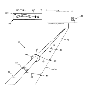
[0058] Figure 1 shows a schematic diagram of an embodiment of the present
disclosure. A monitoring system 10 includes a backbone cable 20 extending
along the length
of a buried structure, shown in this embodiment as a pipeline 30 to be
monitored. For
simplicity, the ground is not shown. A branch cable 40 extends between a
branch cable
junction 50 and a sensing device 60 (e.g. a point sensor or other sensor). The
branch cable
40 may itself provide the functionality of the sensing device 60, such as a
fibre optic cable
(and thus do not require a discrete or separate sensing device 60). A number
of unused
branch cable junctions 70 may be provided along the backbone cable 20 to
provide for future
expansion/addition. One or more flow barriers 100 may be used to reduce or
eliminate the
spread or flow of leaked liquids along the length of the buried structure
(pipeline 30 shown).
[0059] For simplicity, as used herein, the buried structure to be
monitored is referred
to as "a pipeline" but the buried structure may include conduits, waste
containment systems,
sewers, storage tanks, or other underground structures where disturbance or
leak monitoring
- 6 -
CA 2969503 2017-06-02
is required. The buried structure to be monitored may also include buried
cable systems for
power transmission or communications or for civil drainage systems.
[0060] The monitoring system 10 may be installed for a pipeline 30
carrying unrefined
hydrocarbons, refined products, gas, water or other products. In an embodiment
disclosed,
one or more monitoring systems may be installed in a right-of-way or utility
corridor where a
plurality of pipelines 30 or other buried structures have been placed in close
proximity,
allowing each system to monitor one or more of the buried structures (i.e. one
monitoring
system 10 may be used to monitor for leaks from a plurality of buried
structures in close
proximity).
[0061] In an embodiment disclosed, the monitoring system 10 may be used
to
monitor for disturbances such as: leaks of liquids or gases; incursions by
unauthorized
personnel that may damage the buried structure; theft of equipment, materials
or products;
and ground movement that could damage the buried structure, or combinations
thereof.
[0062] The backbone cable 20 may itself be a sensing device 60 such as a
fibre optic
cable, using techniques such as distributed acoustic sensing to detect a leak
or ground
incursion. In an embodiment disclosed, the backbone cable 20 is a single cable
or an
assembly of one or more types of cables or wires or filaments that are capable
of transmitting
data, signals by various means, electrical power, or a combination thereof to
power sensing
devices 60 or other devices. The backbone cable 20 may have one or more branch
cable
junctions 50 where branch cables 40 or sensing devices 60 can be connected and
data,
signals, power or combinations thereof are transmitted to and from the sensing
devices 60.
[0063] The sensing devices 60 may include, for example: fibre optic
systems that
provide distributed temperature or distributed acoustic sensing (or a
combination thereof);
reactive polymer sensors; vapour sensing tubes; hydrocarbon sensing cables;
optical
sensors; or combinations thereof. Each sensing device 60 is generally
configured to detect a
specific range of products. For example, fibre optic systems can detect a
range of products
since they react to how the product changes the environment around the
pipeline 30 rather
than to the product itself. Distributed acoustic systems using fibre optic
cables are also able
to detect intrusions whereas the other sensor devices described generally
focus on detecting
leaks. One or more types of sensing devices 60 may be selected to detect the
type of
disturbance to be monitored/surveilled.
[0064] The sensing devices 60 and the backbone 20 work with known
electronics
systems 80 to operate the sensing device 60 and to receive/interpret the
results. Power for
- 7 -
CA 2969503 2017-06-02
the sensing devices 60 may be supplied from the electronics systems 80 through
the
backbone 20 or by a separate cable system or solar powered with battery back-
up if
required.
[0065] In an embodiment disclosed, the signal or indication from the
sensing device
60 is received at a monitoring station 90, for example via telecommunication
network or
otherwise, where an indication, recordation, alarm or other notification 310
is provided to an
operator or pipeline control system to take a disturbance response action
(e.g. a leak
response action). The monitoring station 90 may also provide a representation
320, 330 of
the pipeline 30 and the flow barriers 100. The leak response action may
include ceasing
operation of the buried structure (e.g. pipeline 30), reducing pressure,
reducing flowrate,
closing emergency shutdown valves, initiating a leak response plan or
combinations thereof.
The leak response action may be automatic, e.g. by the pipeline control
system.
[0066] The backbone cable 20 may be installed above, below or beside the
buried
structure (e.g. pipeline 30), or may be attached to the pipeline 30, in close
proximity to the
pipeline 30 (e.g. less than 1 m) or at some distance (e.g. several metres)
from the buried
structure (e.g. pipeline 30) depending on the application.
[0067] For new pipelines 30 the backbone cable 20 can be placed anywhere
that is
convenient, preferably during the construction phase so that the backbone
cable 20 could be
placed in a trench with the pipeline 30 before the trench is padded and
backfilled. For
existing pipelines 30, one could excavate to access the pipeline 30, but it
may be more
practical to install the backbone cable 20 in a separate trench or conduit a
safe distance from
the pipeline 30 to reduce the chance of damaging the pipeline 30 by excavation
during
installation of the backbone cable 20.
[0068] The branch cable junctions 50 may be built into the backbone cable
20 when
the backbone cable 20 is manufactured, installed on the backbone cable 20
during
installation, installed on the backbone cable 20 after the backbone cable 20
is installed in the
ground or combinations thereof. The branch cable junctions 50 may include a
direct
connection between the branch cable 40 and the backbone cable 20 or may
include a
junction connector (e.g. tee-connector) or a junction box or combinations
thereof.
[0069] In an embodiment disclosed, the branch cable junctions 50 are
installed at
intervals along the backbone cable 20. In an embodiment disclosed, the
intervals may be
regular intervals or variable intervals or combinations thereof. The interval
between
successive branch cable junctions 50 may be less than lm along the backbone
cable 20 to
- 8 -
CA 2969503 2017-06-02
accommodate areas where multiple sensing devices 60 are required. In other
cases, branch
cable junctions 50 may be placed several kilometres apart if the operator
deems that no
sensing devices 60 are required over a particular segment of the pipeline 30.
[0070] In an embodiment disclosed, the branch cable junctions 50 may be
installed at
selected critical locations along the backbone cable 20 such as in locations
where a leak
would cause greater consequences, such as at or near a river crossing.
[0071] In an embodiment disclosed, the unused branch cable junctions 70
may have
enclosures or coverings that protect the unused branch cable junction 70 from
damage when
installed in the ground but can be accessed or removed after the backbone
cable 20 is
installed in the ground to allow the branch cables 40 or sensing devices 60 to
be added to
unused branch cable junctions 70 as the need arises. The enclosures or
coverings may be
plastic or metallic or any other material suitable for long burial in soil and
wet conditions while
providing a seal to prevent degradation of the unused branch cable junctions
70 and
backbone cable 20.
[0072] In an embodiment disclosed, the branch cable junctions 50 may be
configured
so that the branch cables 40 can be easily replaced or removed without
affecting the integrity
of the backbone cable 20 if the sensing device 60 or branch cable 40 or both
are damaged,
require repair/replacement, become obsolete or are no longer needed. The
branch cable
junction 50 (and unused branch cable junction 70) and connected devices (e.g.
branch
cables 40 or sensing device 60 or both) may incorporate proven or novel "wet
connect" plug-
and-socket type connectors as are used in oilfield and other extreme operating
environments.
[0073] The branch cable 40 may be a sensing device 60 such as, but not
limited to, a
fibre optic cable using distributed acoustic sensing to monitor for unwanted
incursions on the
pipeline right of way or using distributed strain sensing to monitor for
ground movement
around the pipeline 30. In an embodiment disclosed, the branch cable 40
connects one or
more sensing devices 60, that monitor one or more pipelines 30, to the
backbone cable 20.
[0074] Referring generally to Figs. 2A-10B, exemplary configurations for
the flow
barrier 100 are shown. The flow barrier 100 includes a relatively low
permeability (or
impermeable) material around and below the pipeline 30 designed and
constructed to restrict
or prohibit the flow of leaked fluids along the pipeline 30 to facilitate
pooling and/or to direct
leaked liquids to a sensing device 60. While the flow barrier 100 is shown
with a substantially
circular configuration, the outer edge profile of the flow barrier 100 may be
any regular shape
- 9 -
CA 2969503 2017-06-02
(such as circular or rectangular) or may be any irregular or custom shape as
required to
conform to the shape of the buried structure and/or the excavation in which
the buried
structure is situated.
[0075] The flow barrier 100 may be constructed of metal, plastic or other
rigid or
semi-rigid material. In an embodiment disclosed, the flow barrier 100 is sized
to extend
substantially to the edge of the excavation (e.g. trench) around the pipeline
30 to impair flow
through any soil disturbed around the pipeline 30 during initial construction
or any
subsequent excavations to inspect, repair or otherwise expose the pipeline.
Smaller flow
barriers 100 can be used but these will be less effective at impairing flow
than a larger flow
barrier 100.
[0076] In an embodiment disclosed, the flow barriers 100 may be installed
at any
location along the pipeline 30 and at any interval depending on the
requirements of the
pipeline owner/operator. The owner/operators may choose to preferentially
install flow
barriers 100 (and associated sensing device 60) at locations where the
probability of a leak
occurrence may be higher such as in potentially unstable slope regions or over
segments
with unfavourable soil conditions. In areas where the consequences of leaks
may be higher,
such as at water crossings, and these consequences can be reduced by
preventing flow
along the pipeline 30, multiple flow barriers 100 may be installed (e.g. in
tandem or multiple
barriers) adjacent to or in close proximity of each other to provide
redundancy. In other
cases, the flow barriers 100 may be installed at intervals of several
kilometres apart.
[0077] The flow barrier 100 may be made from a single element or may be
made
from a plurality of elements that overlap, interlock or are otherwise joined
to form the flow
barrier 100.
[0078] Referring to Figs. 2A-2D, the flow barrier 100 may be deployed as
separate
elements 110A and 110B. As illustrated, element 110A may be generally U-shaped
and be
positioned on the pipeline 30, rotated, and mating element 110B inserted and
the elements
110A and 110B joined. The separate elements 110A and 110B are connectable and
held
together by one or more fasteners. A flange 120A, 120B is provided to support
the flow
barrier 100 on the pipeline 30.
[0079] Referring to Figs. 3A-3B, the flow barrier 100 may be deployed as
an
assembly of elements 130. The elements 130 may be affixed to the pipeline 30
by a flange
140 to form a circumference. The elements 130 may overlap (Fig. 3A) or abut
(Fig. 3B) to
form a substantially fluid impermeable flow barrier 100. The flow barrier 100
may be
- 10 -
CA 2969503 2017-06-02
deployed into the excavation (210 in Figs. 8A-8B) with the individual elements
130
overlapping, then the elements 130 can be fanned out around the pipeline 30 to
form the flow
barrier 100.
[0080] Referring to Figs. 4A-4B, the flow barrier 100 may be deployed as
a flexible
single element 150 constructed of materials such as metal or plastic that can
be temporarily
bent, twisted or otherwise manipulated to allow it to be installed over the
pipeline 30 but then
will substantially recoil to a shape that conforms to the pipeline 30 to form
a rigid or semi-rigid
flow barrier 100.
[0081] Referring to Figs. 5A-5B, the flow barrier 100 may be deployed as
a
compliant, flexible element, fluid impermeable membrane 160, such as a rubber
sheet (such
as neoprene, butyl or silicone), plastic sheet (such as polyethylene, nylon or
pvc), or textiles
(such as a geotextile impregnated with asphalt, elastomer or polymer). One or
more
stiffening members 170 are provided to add stiffness or strength (such as
supplementary
rods, bars, tubes or integral structures such as ridges, pleats, folds or
crimps in the material
itself) to support the impermeable membrane 160. Stiffening members 170 may
also be used
with other configurations of the flow barrier 100.
[0082] Referring to Figs. 6A-6B, the flow barrier 100 may be deployed as
a structure
180 having tubes or pockets that can be inflated or filled through a material
injection port 185
with material such as expanding foam, slurry or cement to increase the size
and rigidity of
the structure (and thus the flow barrier) and to expand the structure 180 to
conform to the
pipeline 30 and/or the surrounding soil, like a tube or tire. In an exemplary
embodiment, the
structure 180 is installed on or around the pipeline 30 and subsequently
expanded by
injecting cement through port 185 to provide the flow barrier 100. The
structure 180 may form
a generally cylindrical or generally toroidal shape, or other shape as may be
preferential.
[0083] Referring to Figs. 7A-7B, the flow barrier 100 may be deployed as
a plurality
of hinged components 190 connected by pins 200 to facilitate installation on
the pipeline 30.
The number of hinged components 190 must be at least two (Fig. 7A), but may be
several
(seven shown in Fig. 7B).
[0084] Referring to Figs. 8A-8B, in an embodiment disclosed, the flow
barrier 100
may be deployed in an excavation 210 (for example a narrow trench) around an
existing
pipeline 30, for example exposed by a flow of pressurized water and vacuum
(e.g. hydrovac
excavation or daylighting etc.) to reduce the risk of damage to the pipeline
30. The flow
barrier 100 may then be installed, and if applicable one or more sensing
devices 60 deployed
-11 -
CA 2969503 2017-06-02
and connected with the backbone cable 20 at an unused branch cable junction
70, and the
excavation 210 subsequently carefully padded and backfilled.
[0085] The flow barrier 100 may be attached to the buried structure (e.g.
pipeline 30),
and may be attached using mechanical devices or fasteners such as one or more
clamps,
straps or fasteners or may be attached using adhesive products or combinations
thereof. In
an embodiment disclosed, the flow barriers 100 may be pre-installed on
segments of the
pipeline 30 prior to installation of the pipeline 30.
[0086] The flow barrier 100 may be placed in close proximity to the
pipeline 30
without being affixed to the pipeline 30, although it is preferable to reduce
any gap between
the pipeline 30 and the flow barrier 100 as much as possible to prevent or
reduce liquid flow
between the flow barrier 100 and the pipeline 30. The gap, if any, between the
pipeline 30
and the flow barrier 100 may be sealed with a sealing device or a sealant.
[0087] The flow barrier 100 may have a shaped outer edge profile, such as
a regular
shape (such as circular or rectangular), may be designed to fit the general
shape of an
excavation (e.g. trench, hole or pit), or can be customized, prior to or
during installation to
conform to the shape required for a specific application such as where the
flow barrier 100
must conform to an obstruction near the pipeline 30 such as a boulder or an
adjacent
pipeline.
[0088] Referring to Figs. 9A-9D, the flow barrier 100 may incorporate
surface
structures 220 such as tubes, channels or preferential flow paths oriented
linearly (in one
direction such as vertical or horizontal or diagonally), radially (such as
from the centre of the
pipeline 30), circumferentially (as either one or more spiral or concentric
rings) or other
arrangement to direct fluids to a sensing device 60. Referring to Fig. 9B,
channels 230 are
shown generally radial and channels 240 are shown generally circumferential.
The flow
barrier 100 may direct the fluids to the sensing device 60 by guiding the
fluid or by conveying
the fluid by any known physical or chemical means including, for example,
selective capillary
action, selective permeation, density-based displacement, or a combination
thereof.
[0089] The flow barrier 100 may incorporate materials such as
geosynthetic drain
fabric to direct fluids to a sensing device 60 and/or incorporate coatings or
materials (such as
engineered polymers which may or may not incorporate materials such as nano
carbon or
metal particles) that respond to contact with selected fluids such as
hydrocarbons such that
all, or a portion of the surface of the flow barrier 100 functions as a
sensing device 60.
- 12 -
CA 2969503 2017-06-02
[0090] The flow barrier 100 may have troughs, grooves or other such
surface finish
machined or etched or rolled into the surface, material with the desired
surface finish may be
attached to the surface, a permeable material that tends to wick oil-based
products by
capillary action may be attached to the surface of the barrier, or small
diameter capillary
tubes may be affixed to the surface, or combinations thereof.
[0091] Referring to Fig. 10, the flow barrier 100 may be deployed as a
composite
structure with various elements or layers providing different functions. For
example, a rigid
core or base structure 250 of metal provides structural integrity, and one or
more layers of
plastic material 260 (e.g. polymer coating) provide corrosion protection for
the rigid base
structure 250. One or more layers of corrugated structures 270 (e.g.
geotextile) provide flow
conduits and one or more exterior layers of fines filter 280 (e.g. geotextile)
excludes fine soil
particles from clogging the flow conduits of the corrugated structure 270.
[0092] Referring to Fig. 11, if leaked liquid 290 escapes from the
pipeline 30 by a
leak 300 (for example a hole or crack), the liquid 290 flows along the
pipeline 30 in the
disturbed soil 340 in the backfilled trench until it encounters the flow
barrier 100. The liquid
290 is then directed towards sensing device 60 on the flow barrier 100.
Sensing device 60 is
connected by branch cable 40 to branch cable junction 50 on the backbone cable
20. Also
depicted in Fig. 11 is a sensing device 60 proximate to the ground surface 350
and
connected to the backbone cable 20, for example to detect a ground incursion.
[0093] In an embodiment disclosed, the flow barrier 100 restricts or
reduces
migration of the leaked liquid along the buried structure (e.g. pipeline 30).
Even a small or
slow leak which cannot migrate away, is more readily detected by the sensing
devices 60, as
a small leak or slow leak may tend to pool or collect at or near the flow
barrier 100 or sensing
device 60 or both, which may increase the signal to provide notice of the leak
to the
monitoring station 90. In an embodiment disclosed, the flow barrier 100 serves
to form a
collection point to direct the leaked fluid towards at least one of the
sensing devices 60. In an
embodiment disclosed, at least one of the sensing devices 60 is located
between, within, or
near the one or more flow barriers 100.
[0094] In operation, upon a disturbance of the buried structure (e.g. a
ground
incursion or a leak, the sensing device 60 will detect the liquid 290 and/or
the ground
incursion and the signal is conveyed along the backbone cable 20 to the
electronics system
80 and transmitted to the monitoring station 90 to alert an operator to shut
down the pipeline
30 or take an appropriate leak response action. If the event is a leak, the
flow barriers 100
- 13 -
CA 2969503 2017-06-02
would restrict the flow of the liquid 290 along the pipeline 30 and the liquid
290 would then be
directed to sensing device 60.
[0095] In the preceding description, for purposes of explanation,
numerous details
are set forth in order to provide a thorough understanding of the embodiments.
However, it
will be apparent to one skilled in the art that these specific details are not
required. In other
instances, well-known structures are shown in block diagram form in order not
to obscure the
understanding.
[0096] The above-described embodiments are intended to be examples only.
Alterations, modifications and variations can be effected to the particular
embodiments by
those of skill in the art. The scope of the claims should not be limited by
the particular
embodiments set forth herein, but should be construed in a manner consistent
with the
specification as a whole.
- 14 -
CA 2969503 2017-06-02