Note: Descriptions are shown in the official language in which they were submitted.
A8141117CADIV 1
TITLE: SYSTEMS AND METHODS FOR THE CAPTURE OF HEAT ENERGY,
LONG-DISTANCE CONVEYANCE, STORAGE, AND DISTRIBUTION
OF THE CAPTURED-HEAT ENERGY AND POWER GENERATED
THEREFROM
TECHNICAL FIELD
Various embodiments disclosed herein generally relate to systems,
equipment, and methods for capture of heat energy and the long-distance
conveyance, storage, and distribution of the captured-heat energy to users.
More
specifically, this disclosure relates to the long-distance conveyance,
storage, and
distribution of captured-heat energy at ambient temperatures by utilizing the
latent
heat energy of low-boiling-point fluids in conveyance lines, and to the
utilization of
some of the captured-heat energy for power the generation at or near heat
capture
locations.
BACKGROUND
The effective capture and utilization of heat energy, in particular lower-
temperature heat energy from sources such as geothermal, thermal solar, waste
heat, cogeneration, combined heat and power (CHP), fueled boiler-heater,
steam,
and the like, for generating power and providing heating offers vast potential
for
energy efficiencies, development of renewable energy sources, and reduction of
CO2 emissions.
There have been considerable efforts to capture and utilize these types of
heat energy either as stand-alone projects or through district energy
distribution
systems, often also known as district heating systems, district energy sharing
systems, or community distributed energy systems.
Historically, district heating systems have been largely fuel-fired central
heating plants, often with cogeneration, that produce and distribute the heat
energy as high-temperature steam or hot water. Most district energy sharing
installations in North America are part of institutional infrastructures such
as
hospital complexes, university campuses, and in urban centers. In Europe, many
Date Recue/Date Received 2020-12-14
A8141117CADIV 2
district heating systems are located in urban centers and are similarly
characterized by combustion-fueled heating plants that distribute steam or hot
water. One limitation of such systems is the limited feasible areal extent due
to
heat losses from flowlines that carry steam or hot water. Furthermore, such
district
heating systems and district energy sharing systems are not systems per se
because they simply deliver heat energy in one direction in response to
demand.
Many district heat systems have been commissioned to utilize low-
temperature heat energy sources such as low-enthalpy (low temperature)
geothermal sources. However, the utilization of fluids such as hot water,
limits the
temperature ranges available for use to convey and deliver captured-heat
energy
via the sensible heat contained in the hot water and thereby, limits the
feasible
areal extent of such systems.
Organic Rankine Cycle (ORC) and other technologies such as Kalina cycle,
sterling engine cycle, absorption, and the like, have been implemented to
generate
power from lower-temperature heat energy sources, whereby low-temperature
vaporization-point fluids also commonly referred to as low-boiling-point
fluids,
such as ammonia, commercial refrigerants, CO2, volatile hydrocarbons, and the
like are utilized. Heat energy that is not converted to mechanical energy for
power
generation is normally ejected because the exit temperatures are too low for
heat
utilization. As well, heat-sink temperatures restricted to ambient
temperatures
limit the viability of lower-temperature heat sources for power generation.
Many communities, industrial installations, and resource-extraction
installations are isolated from cost-effective power and energy supply and
distribution infrastructures because they may be located in remote sparsely
populated areas or in regions with poor infrastructures. Often these
communities
and installations have to rely on high-transport-cost bulk liquid fuels such
as diesel,
to power generators and for fuel-fired heating. In arctic and near-arctic
regions,
transportation of such materials is often seasonal with water-barge transport
during the summer months and by overland road trucking in the winter, and in
certain cases, via air. Also, on-site construction, installation, and
commissioning
costs are very high in such regions.
Date Recue/Date Received 2020-12-14
A8141117CADIV 3
Impacts of catastrophic events such as hurricanes and earthquakes require
stand-alone self-sufficient power generation and heating capacity that can be
quickly set up on an emergency or temporary basis.
SUMMARY
The embodiments of the present disclosure generally relate to stand-alone
systems, apparatus, and methods for:
(I) capturing
heat energy from sources such as geothermal, thermal solar,
waste heat, cogeneration, combined heat and power (CHP), fueled boiler-
heater, steam, and the like;
(ii) employing a portion
of the captured-heat energy for generation of electrical
power utilizing Organic Rankine Cycle (ORC) or other technologies such
as Kalina cycle, sterling engine cycle, absorption, and the like;
(iii)
transferring and converting the remaining captured-heat energy to the
latent heat of a low-boiling point-liquid by vaporization into its vapor
phase;
(iv) conveying over long
distances, the captured-heat energy contained in the
vapor of the low-boiling-point liquid as latent heat at ambient temperatures
instead of as high-temperature sensible heat in hot liquids or as latent heat
in high-boiling-point fluids; and
(v) converting
the conveyed latent heat energy to sensible heat energy at a
delivery site by condensing the vapor of the low-boiling-point liquid into its
liquid phase.
According to one embodiment of the present disclosure, the long-distance
conveyance of heat energy at ambient temperatures by the stand-alone systems,
apparatus, and methods disclosed herein, is enabled through the deployment of
two or more closed-loop circulation systems connected in series, wherein each
of
said closed-loops utilizes low-temperature vaporization-point fluids (i.e.,
low-
boiling-point fluids) such as, for example, ethane, ammonia, commercial
refrigerants, CO2, volatile hydrocarbons, and the like. Aspects of the
embodiments
Date Recue/Date Received 2020-12-14
A8141117CADIV 4
disclosed herein include power generation systems that incorporate lower heat-
sink temperatures in the power generation cycle (i.e., loop), thereby opening
up
opportunities to generate more power from lower-temperature heat sources.
Another embodiment of the present disclosure relates to the bundling of
long-distance flowlines along with power and communication cables via
installing
them by way of methods such as, but not limited to, bundling as "umbilical
cords"
within tubing or wraps, or by placement of the bundled flowlines and cables
into
one trench or alternatively, by placement of separated flowlines and cables
into
two or more closely spaced-together trenches, or by ploughing the bundled
flowlines into one run or alternatively by ploughing separated flowlines and
cables
into two or more closely spaced-together runs, or by drawing the bundled
flowlines
through one bore or alternatively by drawing separated flowlines and cables
through two or more closely spaced-together bores, or by placing the flowlines
and cables near to each other on ground surfaces or on above-ground cable and
pipe support racks.
Another embodiment of the present disclosure relates for equipment
configurations into integrated heat energy capture, storage, distribution, and
delivery systems wherein included are network sharing and controls systems.
The
integrated heat energy capture, storage, distribution, and delivery systems
have
the means and capacity to generate at least some or alternatively all, or
alternatively, a surplus of power requisite for operation of the systems.
Additionally, the present integrated heat energy capture, storage,
distribution, and
delivery systems enable installation and stand-alone operation of smart-energy
distribution and sharing systems in isolated regions and also, within larger
established energy infrastructure systems.
Another embodiment of the present disclosure relates to the incorporation
of systems of meters and data collection systems for the recording and
assembly
of mass flows and energy flows that can be used to calculate heat-energy-
transfer
quantities for invoicing, payment, and other financial purposes.
Another embodiment of the present disclosure relates to a modular
approach for configuring the equipment, apparatus, and systems disclosed
herein,
Date Recue/Date Received 2020-12-14
A8141117CADIV 5
onto and into transportable skids or trailers, whereby the equipment,
apparatus
and systems may be manufactured and configured at selected industrial
locations,
and then transported to remote installation sites for rapid installation and
commissioning of power generation and heating while minimizing on-site
construction costs. Additionally, the transportable modularized equipment,
apparatus, and systems are useful for rapid response and deployment on a
temporary basis to locations that sustained loss of power and energy
infrastructures as a consequence of severe weather events such as hurricanes,
tornados, and the like.
Another embodiment of the present disclosure relates to configurations of
the equipment, apparatus, and systems into manufactured self-contained modular
units that can be fitted into confined residential spaces and/or confined
commercial, wherein the configurations are provided with standardized couplers
and receptacles designed for ease-of-connection. According to one aspect, the
manufactured self-contained modular units are inter-connectable as multiple
units
at a location to facilitate scaling-up of heat-energy and power supply
capacity.
DESCRIPTION OF THE DRAWINGS
These and other features of the disclosure will become more apparent in
the following detailed description in which reference is made to the appended
drawings, wherein:
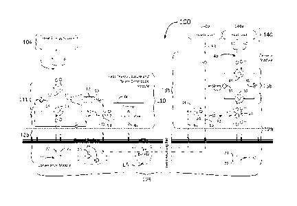
Fig. 1 is a schematic flowchart illustrating an embodiment disclosed herein
of a stand-alone long-distance three-loop closed-loop heat energy capture,
generation of power from a portion of the captured-heat energy, conveyance,
and
delivery system 100;
Fig. 2 is the schematic flowchart shown in Fig. 1 with additional references
to certain components of the system;
Fig. 3 is a cross-sectional view taken from Fig. 1, of the long-distance
conveyance components of the system shown in Figs. 1 and 2 wherein long-
distance flowlines, power cables, and communications cables are bundled
Date Recue/Date Received 2020-12-14
A8141117CADIV 6
together into an "umbilical cord" configuration;
Fig. 4 is a schematic flowchart showing a view of the heat energy capture
and power generation loop 111 of the system 100 shown in Figs. 1 and 2,
wherein
the heat energy source 104 comprises heat energy captured from one or more of
geothermal, thermal solar, and waste heat sources, wherein a portion of the
captured-heat energy is used to produce power, and wherein the heat energy
capture and power generation module 110 receives an external supply of power
106;
Fig. 5 is a schematic flowchart showing a view of the heat energy capture
and power generation loop 111 of the system 100 shown in Figs. 1 and 2,
illustrating an additional input of heat energy captured from a fueled boiler-
heater;
Fig. 6 is a schematic flowchart showing a view of another embodiment of a
system 100 wherein the heat energy capture and power generation loop 111
captures heat energy directly from a heat energy source 104 and a portion of
the
captured heat energy is used for power generation, according to another
embodiment of the present disclosure;
Fig. 7 is schematic flowchart showing another view of the heat energy
capture and power generation loop 111 of the system 100 shown in Fig. 6,
wherein
the heat energy source 104 comprises heat energy captured from one or more of
geothermal 104a, thermal solar 104b, and waste heat 104c sources, wherein a
portion of the captured-heat energy is used to produce power,
Fig. 8 is a schematic flowchart showing a view of the heat energy capture
and power generation module 110 of the system 100 shown in Figs. 1 and 2,
wherein an external supply of power 106 is provided;
Fig. 9 is a schematic flowchart showing a view of the heat energy capture
and power generation module 110 of the system 100 shown in Figs. 1 and 2,
illustrating an additional input of power captured by PV solar cells 106a
and/or by
wind turbines 106b into the external supply of power 106;
Fig. 10 is a schematic flowchart showing a view of the heat energy capture
Date Recue/Date Received 2020-12-14
A8141117CADIV 7
and power generation module 110 of the system 100 shown in Figs. 1 and 2,
illustrating additional power inputs from one or more of an electrical grid, a
smart
energy grid, and a local distributed electrical grid into the external supply
of power
106;
Fig. 11 is a schematic flowchart showing a view of a heat energy capture
and power generation module 210 of another embodiment of a stand-alone long-
distance three-loop closed-loop heat energy capture, conveyance, and delivery
system 200, wherein none of the heat energy captured from one or more heat
energy sources 204 is used for power production in the heat energy capture
module 210, and an external supply of power 206 is provided;
Fig. 12 is a schematic flowchart showing a view of an optional modification
300 to the heat energy capture, conveyance, and delivery system 100
illustrated
in Figs. 1 and 2, wherein the long-distance conveyance loop 326 of the long-
distance conveyance module is also the heat energy delivery loop 336;
Fig. 13 is a schematic flowchart illustrating an embodiment of the present
disclosure of the self-sufficient stand-alone long-distance three-loop closed-
loop
heat energy capture, storage, distribution, delivery, storage, and sharing
system
400, for capturing heat energy from a single heat energy source, generating
power
from a portion of the captured-heat energy, then conveying and delivering the
captured-heat energy and power therefrom along a conveyance infrastructure to
multiple delivery modules;
Fig. 14 is a schematic flowchart illustrating another embodiment of the
present disclosure of a self-sufficient stand-alone long-distance three-loop
closed-
loop heat energy capture, storage, distribution, delivery, storage, and
sharing
system 500, wherein heat energy is captured from a plurality of heat energy
sources and conveyed along a main trunk line, generating power from portions
of
the captured-heat energy, and delivering the captured-heat energy and power
from the main trunk line to multiple delivery modules;
Fig. 15 is a key for the symbols used in Figs. 11 and 12;
Fig. 16 is a schematic flowchart illustrating the locations of the working
fluid
Date Recue/Date Received 2020-12-14
A8141117CADIV 8
thermodynamic properties that were modelled for each of the three closed loops
shown in Figs. 1 and 2, as discussed in Examples 1 and 2;
Fig. 17 is a schematic flowchart illustrating the locations of the circulating
working fluid thermodynamic properties that were modelled for the second
closed-
loop module 335 shown in Fig. 12, as discussed in Examples 3 and 4;
Fig. 18 is a table summarizing the operating parameters used for the
thermodynamic model outlined in Example 1;
Fig. 19 is a chart showing the saturation (vapor) pressure curves for some
examples of low-boiling-point fluids suitable for use in the heat energy
conveyance
loops disclosed herein;
Fig. 20 is a chart showing the enthalpy curves for some low-boiling-point
fluids suitable for use in the heat energy conveyance loops disclosed herein;
Fig. 21 is a chart showing the entropy curves for some low-boiling-point
fluids suitable for use in the heat energy conveyance loops disclosed herein;
Figs. 22A and 22B are charts showing the enthalpy curves (Fig. 22A) and
entropy curves (Fig. 22B) for the working fluid used in the heat energy
capture and
power generation loop for the thermodynamic model outlined in Example 1;
Figs. 23A and 23B are charts showing the enthalpy curves (Fig. 23A) and
entropy curves (Fig. 23B) for the working fluid used in the long-distance
conveyance loop for the thermodynamic model outlined in Example 1;
Figs. 24A and 24B are charts showing the enthalpy curves (Fig. 24A) and
entropy curves (Fig. 24B) for the working fluid used in the delivery loop for
the
thermodynamic model outlined in Example 1;
Fig. 25 is a table summarizing the results of energy balance calculations
generated by the thermodynamic model outlined in Example 1;
Figs. 26A and 26B are charts showing the relationship between heat source
temperature (Fig. 26A) and the fraction of heat energy that is available for
power
generation (Fig. 26B) in the calculations modelled by the thermodynamic model
Date Recue/Date Received 2020-12-14
A8141117CADIV 9
outlined in Example 1;
Fig. 27 is a table summarizing the results of modelling a long-distance
three-loop closed-loop heat energy capture, storage, distribution, delivery,
storage, and sharing system that delivers heat energy and power from one heat
energy capture and power generation module to several users, as outlined in
Example 2;
Fig. 28 is a table summarizing the operating parameters used for the
thermodynamic model outlined in Example 3 that is a model of an example of a
two-loop closed-loop system disclosed herein;
Fig. 29 is a table summarizing the results of energy balance calculations
generated by the thermodynamic model outlined in Example 3;
Figs. 30A and 30B are charts showing the relationship between heat source
temperature (Fig. 30A) and the fraction of heat energy that is available for
power
generation (Fig. 30B) in the calculations modelled by the thermodynamic model
outlined in Example 3; and
Fig. 31 is a table summarizing the results of modelling a long-distance two-
loop closed-loop heat energy capture, storage, distribution, delivery,
storage, and
sharing system that supplies heat energy and power from one heat energy
capture
and power generation module to several users as outlined in Example 4.
DETAILED DESCRIPTION
The embodiments of the present disclosure generally relate to integrated
systems, apparatus, and methods for the capture of heat energy and for the
long-
distance conveyance, storage, and distribution of the captured-heat energy at
ambient temperatures. The long-distance conveyance and distribution of the
captured-heat energy is facilitated by utilizing the latent heat energy of low-
boiling-
point (LBP) fluids in closed-loop conveyance lines. Some embodiments relate to
the utilization of some of the heat energy for the generation of power at or
near
heat capture locations.
Date Recue/Date Received 2020-12-14
A8141117CADIV 10
One embodiment of the present disclosure relates to the long-distance
conveyance (transportation) of heat energy at ambient temperatures as latent
heat
energy via a fluid in its vapor phase instead of as sensible heat.
Another embodiment of the present disclosure relates to the long-distance
conveyance of latent heat energy, via a fluid in its vapor phase, from a
source of
heat energy to a heat energy delivery site using a two-loop closed-loop
system, or
alternatively a three-loop closed-loop system, in locations having ambient
temperatures from a range of -40 C to +50 C.
Another embodiment of the present disclosure relates to the ability to
convey heat energy long distances at below-freezing temperatures (less than 0
C)
thereby enabling the conveyance of heat energy through subsurfaces in regions
with permafrost without thawing the permafrost.
According to a first aspect, the two-loop closed-loop systems disclosed
herein generally consist of two loops wherein the first loop comprises
equipment
and systems configured for capturing and transferring heat energy from a heat
energy source as well as for generating power. The second loop comprises
equipment, systems, and controls configured for receiving the captured-heat
energy from the first loop, for conveying the captured-heat energy for long
distances, and for delivering the captured-heat energy to consumers. In regard
to
the first aspect, the first loop is referred to herein as a "heat energy
capture and
power generation loop", and the second loop is referred to herein as a "long-
distance captured-heat energy conveyance and delivery loop". According to a
second aspect, the three-loop closed-loop systems disclosed herein generally
consist of three loops wherein the first loop comprises equipment, systems,
and
controls configured for capturing and transferring heat energy from a heat
energy
source as well as for generating power. The second loop comprises equipment,
systems, and controls configured for receiving the captured-heat energy from
the
first loop, for conveying the captured-heat energy for long distances and then
transferring the captured-heat energy to a third loop which comprises
equipment,
systems, and controls configured delivering the captured-heat energy to
consumers. In regard to the second aspect, the first loop is referred to
herein as a
"heat energy capture and power generation loop", the second loop is referred
to
Date Recue/Date Received 2020-12-14
A8141117CADIV 11
herein as a "long-distance heat energy conveyance loop", and the third module
is
referred to as a "heat energy delivery module".
According to another aspect, the second loop may convey heat energy for
long distances at below freezing temperatures (less than 0 C) thereby enabling
the conveyance of heat through the subsurface in regions with permafrost
without
thawing the permafrost. According to another aspect, the second loop may
convey
heat energy for long distances on permafrost surfaces without thawing the
permafrost surfaces.
Another embodiment of the present disclosure relates to use of a portion of
the captured-heat energy to generate electrical power for use to power
equipment
requisite for operation of the first module, wherein the first module is
configured
for capturing the heat energy and transferring the captured-heat energy and
generated power to the second module, i.e., the long-distance conveyance
module. According to one aspect, excess electrical power generated in the
first
module may be conveyed in the second module for delivery to power consumers,
and optionally to provide electrical power for use to power equipment
requisite for
delivery of the captured-heat energy to a consumer. According to another
aspect,
supplemental power may be provided to the first module for powering equipment
requisite for operation of the first module, and optionally, for long-distance
conveyance and delivery to a power consumer. In regard to this embodiment, the
first module may be referred to as a "heat energy capture and power generation
module", the second module may be referred to as a "long-distance captured-
heat
energy and power transmission module", and the third module may be referred to
as a "captured-heat energy and power delivery module".
Another embodiment of the present disclosure relates to configuration of
systems and related methods of operation into two-loop or three-loop closed-
loop
integrated heat energy capture, storage, distribution, delivery, storage, and
sharing systems, which depending on the temperature of the captured heat
energy, can generate some, all, or a surplus of its power requirements, enable
the
installation of self-sufficient smart energy distribution and sharing systems
able to
stand alone in situations where such systems are useful and/or additionally,
in
isolated locations.
Date Recue/Date Received 2020-12-14
A8141117CADIV 12
Another embodiment of the present disclosure relates to a stand-alone and
self-sufficient system comprising equipment and controls that are integrated
into
the two-loop closed-loop and three-loop closed-loop systems, apparatus, and
methods for the capture of heat energy and for the long-distance conveyance,
storage, and distribution of the captured-heat energy. According to one
aspect,
the stand-alone equipment and control system may be monitored and operated
by on-site operators. According to another aspect, the stand-alone equipment
and
control system may be monitored and operated by remotely located operators and
optionally, on a semi-attended basis. According to another aspect, the stand-
alone
equipment and control system may be monitored and controlled by on on-site
operators and concurrently monitored by remotely located operators.
Another embodiment of the present disclose relates to providing a control
and communication system interconnected with and in communication with an
integrated system, apparatus, and related methods for the capture of heat
energy
and for the long-distance conveyance, storage, and distribution of the
captured-
heat energy configured as disclosed herein, wherein the control and
communication system is programmable to monitor and record (i) selected
parameters associated with the flows of the LBP working fluids within and
throughout each of the closed-loop piping infrastructures, (ii) the operating
performance of each apparatus in communication with each of the closed-loop
piping infrastructure, and (iii) to control in accordance with predefined
optimization
parameters, one or more of the apparatus to optimize flows of the LBP working
fluids within and throughout each of the closed-loop piping infrastructures,
whereby the delivery of the captured heat energy is optimized. According to
one
aspect, the control and communication system may be configured for continuous
on-site monitoring and control. According to another aspect, the control and
communication system may be configured for continuous remote monitoring and
control, According to another aspect, the control and communication system may
be configured for integrated continuous remote monitoring and control and
remote
monitoring and control. According to another aspect, the control and
communication system may be integrated with a "smart energy system" whereby
process operations as well as the capture, long-distance conveyance, storage,
and distribution of heat energy, power, and power generated therefrom, are
Date Recue/Date Received 2020-12-14
A8141117CADIV 13
automatically optimized.
Another embodiment of the present disclosure relates to a system of meters
and meter-monitoring systems integrated into each of the modules disclosed
herein, to monitor, quantify, and record the flows of captured-heat energy and
power within and between each of the loops comprising the systems disclosed
herein, whereby the capture and conveyance of heat energy and power generated
therefrom and optionally provided thereto, can be monetized.
Another embodiment of the present disclosure relates to systems that
comprise a long-distance captured-heat energy and power-transmission trunk
conveyance module interconnected with (i) a plurality of heat energy capture
modules and/or heat energy capture and power generation modules that transfer
captured-heat energy and generated power to the long-distance captured-heat
energy and power-transmission trunk conveyance module, and (ii) a plurality of
captured-heat energy and power delivery modules wherein each of the captured-
heat energy and power delivery modules receives a portion of the captured-heat
energy and power conveyed along the long-distance captured-heat energy and
power-transmission trunk conveyance module. According to one aspect, systems
comprising a long-distance captured-heat energy and power-transmission trunk
conveyance module, interconnected with (i) a plurality of heat energy capture
modules and/or heat energy capture and power generation modules (i.e., first
modules), and (ii) a plurality of captured-heat energy and power delivery
modules
(i.e., third modules), may additionally comprise one or more heat sinks
interconnected thereto. Examples of suitable heat sinks include subterranean
geological formations and subterranean water bodies. Each heat sink may be
interconnected with the long-distance captured-heat energy and power-
transmission trunk conveyance module by flowlines wherein is circulating a LBP
working fluid.
Another embodiment of the present disclosure relates to equipment and
component configurations for the first module (i.e., the heat energy capture
and
power generation module) and for the third module (i.e., the heat energy
delivery
module) into standardized manufactured self-contained modular units that may
be
fitted into confined residential spaces and/or confined commercial spaces,
Date Recue/Date Received 2020-12-14
A8141117CADIV 14
whereby depending on a particular application, the modular units may comprise
height-width-depth sizes from the ranges of about lm to 4m per side (for
example,
approximate sizes similar to one to four kitchen refrigerators or freezers
According
to an aspect the standardized manufactured self-contained modular units may be
provided with standardized quick-release standardised couplers and receptacles
designed to facilitate demountable engagement of the modular units with
flowlines, and cables.
Another embodiment of the present disclosure relates to configuring and
installing the equipment components for the first module (i.e., the heat
energy
capture and power generation module) and for the third module (i.e., the heat
energy delivery module), onto transportable skids. The modular skids may be
configured and fabricated at suitable manufacturing facilities and then
transported
to remote sites for installation, commissioning, and use. For example, the
modular
skids may be sized to fit onto the decks of flat-bed trailers for hauling
and/or
carriage by heavy-duty over-road truck tractors and/or by rail and/or by
barges
and/or by ships. Examples of suitable skid dimensions include: (i) North
American
specifications for flat-bed trailer decks having widths of 8.5' (2.6 m) and
lengths
ranging between 40' (12.2 m) and 63' (19.2 m) , and (ii) European
specifications
for flat-bed decks having widths of 2.55 m (8.4') and lengths ranging between
12
m (39.4') and 18.5 m (60.7'). It is optional for the skid-mounted modules to
be
enclosed with sidewalls and roofs for protection from environmental conditions
and to prevent vandalism. Particularly suitable are intermodal shipping
containers
that are designed and built for intermodal freight transport. Those skilled in
this art
will understand that intermodal containers are designed such that they can be
used for shipping goods with multiple modes of transport options such as by
ship,
by rail, by truck, and by air. Intermodal container handling equipment is
commonly
available at cargo receiving and distribution facilities, for loading and
unloading
the same types of intermodal containers onto and from a ship, onto and from a
rail
car, onto and from a transport truck trailer, and onto and from a cargo
airplane.
Intermodal containers commonly have dimensions that are: (i) either twenty
feet
or forty feet (6.1 m or 12.2 m) long, (ii) eight and a half feet or nine and a
half feet
(2.6 m or 2.9 m) high, and (iii) six and a quarter feet of eight feet (1.9 m
or 2.44 m)
wide, and are configured to fit onto the decks of North American trailer decks
and
Date Recue/Date Received 2020-12-14
A8141117CADIV 15
European trailer decks. Those skilled in this art will know that such
intermodal
containers have numerous common names including sea-cans, C-cans, Conex
boxes, cargo containers, among others.
The skid-mounted modules disclosed herein may be configured for use in
remote harsh environmental conditions (for example tundra permafrost, desert),
or in isolated mining camps, or in refugee camps, or in remote military
installations
and staging areas. The skid-mounted modules disclosed herein may also be
configured into/onto smaller skids/trailer units towable by 2-wheel-drive
and/or 4-
wheel-drive vehicles for rapid deployment and commissioning to provide
emergency power and heating supplies to population areas wherein their power
and energy infrastructures were catastrophically damaged by severe weather
such as hurricanes, tornadoes, and the like.
According to some aspects, the integrated systems, apparatus, and
methods disclosed herein pertain to the capture of heat energy from geothermal
sources, from thermal solar sources, from waste heat emitted via exhaust gases
from internal-combustion engines, flue gases from combustion processes, from
fueled boiler-heater plants, from steam plants, from hot or warm waste streams
from processing facilities, from cogeneration of heat and electricity, from
combined
heat and power (CHP) plants, and the like.
According to some aspects, heat energy captured by the integrated
systems, apparatus, and methods disclosed herein, is used to convert LBP
fluids
circulating in closed-loop conveyance lines comprising the systems from their
fluid
phase into their vapor phase.
According to some aspects, the integrated systems, apparatus, and
methods disclosed herein, may be configured to capture heat energy by
circulating
LBP working fluids as well as by fluids such as water, hot oil, glycol
solution,
gases, and the like, with or without causing a phase change.
According to some aspects, the integrated systems, apparatus, and
methods disclosed herein, may be configured to deliver heat energy by
circulating
LBP working fluids as well fluids such as water, hot oil, glycol solution,
gases
including combustion gases, and the like, with or without phase change.
Date Recue/Date Received 2020-12-14
A8141117CADIV 16
Unless otherwise defined, all technical and scientific terms used herein
generally have the same meaning as commonly understood by one of ordinary
skill in the art to which this disclosure pertains. Exemplary terms are
defined
below for ease in understanding the disclosure described herein.
The term "a" or "an" refers to one or more of that entity; for example, "a
gene" refers to one or more genes or at least one gene. As such, the terms "a"
(or "an"), "one or more" and "at least one" are used interchangeably herein.
In
addition, reference to an element or feature by the indefinite article "a" or
"an"
does not exclude the possibility that more than one of the elements or
features
are present, unless the context clearly requires that there is one and only
one of
the elements.
The term "about" as used herein is meant to encompass variations of
20%, 10%, 5%, 1%, 0.5% or 0.1% of the specified amount. When the
value is a whole number, the term about is meant to encompass decimal values,
as well the degree of variation just described.
The term "ambient temperature" as used herein means means the
temperature of the surrounding environment measured as atmospheric
temperature. The surrounding environment may be above ground level wherein
the ambient temperature will be the average temperature of the air in a band
that
extends to about 30 m above the ground surface, will vary with the latitude of
a
location or region and its annual seasonal cycle, and may be in the range of -
50 C to over 50 C. Alternatively, the surrounding environment may be below the
ground surface level in which case, the ambient temperature will the
temperature
of the surrounding subsoil layers and may also be in the range of -40 C to
about
40 C.
The term "and/or" refers to and encompasses any and all possible
combinations of one or more of the associated listed items (e.g. one or the
other,
or both), as well as the lack of combinations when interrupted in the
alternative
(or).
Date Recue/Date Received 2020-12-14
A8141117CADIV 17
As used herein, the term "enthalpy" refers to a thermodynamic
quantity equivalent to the total energy content of a substance, and is equal
to the
internal energy of the system plus the product of pressure and volume.
As used herein, the term "latent heat energy" refers to the heat energy
released from or absorbed by condensing or vaporizing a fluid circulating
within
the closed-loop heat-energy conveyance systems disclosed herein.
As used herein, the term latent heat as used herein refers to the energy
absorbed or released by a substance during a change in its physical state
(i.e.,
phase) that occurs without changing its temperature. The latent heat
associated
with vaporizing a liquid or a solid or condensing a vapor is called the heat
of
vaporization. The latent heat is normally expressed as the amount of heat (in
units of joules or calories) per mole or unit mass of the substance undergoing
a
change of state.
As used herein, the term "low-boiling-point fluid" (low-temperature
vaporization-point fluid) refers to a fluid that boils (i.e., vaporizes) i.e.,
undergoes
a phase change from liquid to vapor at a temperature of about -30 C or less at
1
Bar (one atmosphere of pressure). Examples of low-boiling-point fluids
suitable
for use and conveyance in the closed-loop circulation systems disclosed
herein,
include but are not restricted to ammonia (BP about -36 C), CO2 (BP about -
78 C), ethane (BP about -88 C), chlorodifluoromethane refrigerant R-22 (BP
about -41 C), dichlorodifluoromethane refrigerant R-12 (BP about -30 C),
difluoromethane R-32 (BP about -52 C), other commercial refrigerants, propane
(BP about -42 C), propene (BP about -47 C), propylene (BP about -47 C), other
volatile hydrocarbons, and the like. The term "low-boiling-point" may be
represented herein by the acronym "LBP".
As used herein, the term "fluid" refers to a substance in the form of a
liquid or a vapor or a gas that flows and conforms to the outline of its
container,
and includes LBP (low-boiling-point, low-vaporization-point) substances such
as
ethane, ammonia, commercial refrigerants, CO2, volatile hydrocarbons as well
substances such as water, hot oil, glycol solution, gases including combustion
gases, flue gases, and the like, with or without phase change.
Date Recue/Date Received 2020-12-14
A8141117CADIV 18
As used herein, the term "sensible heat" refers to the heat energy content
of a circulating liquid without any phase changes, and is a function of
changes in
temperature of the fluid.
As used herein, the term "low-temperature waste heat" means low-
enthalpy waste heat below 140 C that may be captured from waste heat energy
and energy in general from geothermal sources, from thermal solar sources,
from hot or warm processing plant streams, combustion gases, from fueled
boiler-heater plants, from steam plants, from cogeneration of heat and
electricity,
from combined heat and power (CHP) plants, and the like.
As used herein, the term "geothermal body" refers to: (i) geothermal
energy contained within geothermal geological formations such as subterranean
warm or subterranean hot, dry crystalline basement rock and to deep warm
aquifers and deep hot aquifers contained in fractured crystalline basement
rock
(also referred to herein as a "geothermal geological formation"),(ii) near-
surface
subsoils and fresh water aquifers, and (iii) to bodies of water, that may or
may
not be heated by geothermal energy.
As used herein, the term "PV solar" refers to electricity provided from
photovoltaic solar cells that convert light energy (i.e., photons) into
voltage.
As used herein, the term "electrical grid" refers to refers to an
interconnected network for delivering electricity from producers to consumers.
Electrical grids comprise generating facilities that produce electrical power,
transmission lines that carry electrical power from sources to distribution
centres,
and distribution lines that connect individual customers to distribution
centres.
As used herein, the term "smart energy grid" refers to refers to an
integrated network that controls in real time the generation, supply,
distribution,
use, and storage of electricity and heat energy within an interconnected
system
of devices, through the two-way control and distribution of electricity and
heat
energy. A smart energy grid comprises interactive controls, control systems,
automated devices, and equipment.
Date Recue/Date Received 2020-12-14
A8141117CADIV 19
As used herein, the term "local distributed electrical grid" refers to a
"smart energy grid" that is local to an area or community, and not part of a
widely
distributed integrated electrical management network.
One embodiment of the present disclosure relates to a stand-alone system
and related apparatus and equipment for capture of heat energy, and for the
long-
distance conveyance, storage, and distribution of the captured-heat energy to
users. The captured-heat energy is captured, conveyed, and delivered by
utilizing
the latent heat energy of LBP fluids in closed-loop conveyance lines that are
in
communication with: (i) one or more sources of heat energy and (ii) one or
more
delivery sites whereto the captured-heat energy is transferred.
According to one aspect, one or more flowlines wherein is circulating a LBP
fluid, with or without phase changes, may be employed for capturing heat
energy
from a geothermal source, or a thermal solar source, or from hot or warm
processing plant streams, or from combustion gas waste heat, or from a
combustion-fired heating plant, or from a cogeneration facility, or from a
combined
heat and power (CHP) facility, from a fueled boiler-heater facility, or other
such
sources. In particular, the embodiments disclosed herein are particularly
useful for
capturing low-temperate waste heat (i.e., having a temperature of less than
140 C)
from such sources.
According to another aspect, a portion of the waste heat energy captured
by the systems, apparatus, and methods disclosed herein, may be used for
generating electricity with one or more of technologies and equipment based
on,
for example, the Organic Rankine Cycle (ORC), the Kalina cycle, sterling
engine
cycle, or absorption. It is within the scope of this disclosure for such
systems and
apparatus to use the portion of the heat energy for generation of electricity
nearby
the source(s) from where the heat energy is captured. It is also within the
scope
of this disclosure for such systems and apparatus to use the portion of the
captured-heat energy for generation of electricity nearby delivery sites and
the
users of the captured-heat energy.
According to another aspect, the remaining captured-heat energy not used
for generation of electricity, may be transferred and converted into the
latent heat
Date Recue/Date Received 2020-12-14
A8141117CADIV 20
of a fluid by vaporizing a LBP liquid into its vapor phase in a closed-loop
piping
infrastructure, conveying the captured-heat energy in the LBP liquid's vapor
phase
as latent heat in one or more closed-loop piping infrastructures at ambient
temperatures over long distances at ambient external temperatures to delivery
sites. The captured-heat energy is released from the LBP liquid by condensing
the
vapor phase into the liquid phase whereby that the conveyed latent heat energy
is converted to sensible heat. The sensible heat is then distributed to
heating
apparatus such as radiant heaters, air-circulating heaters, and the like, or
alternatively, via intermediate systems such as circulation of hot water.
Some embodiments of the present disclosure relate to bundling long-
distance closed-loop flowlines together with electrical cables and
communication
cables by way of forming "umbilical cords" with tubing or wraps, or
alternatively,
placement of the flowlines and cables into one trench or into adjacent
trenches, or
alternatively, ploughing the flowlines and cables into on run or into adjacent
runs,
or alternatively, drawing the flowlines and cables through one bore or through
adjacent bores, or by placing the flowlines and cables near to each other on
the
surface or on above ground electrical cable and pipe supports.
Some embodiments of the present disclosure relate to incorporation of a
system of meters and a data monitoring and control system for recording mass
flow data and energy flow data, and for the processing and assembly of the
data
for calculations of heat energy capture, transfer, and delivery amounts for
use in
monetization of the heat energy capture, the conveyance of the captured-heat
energy, and the delivery of the captured-heat energy to consumers.
Some embodiments of the present disclosure relate to configuring the
various apparatus and equipment requisite for the systems and methods
disclosed
herein, into modules that will fit onto transportable skids or into trailers,
thereby
enabling an economical manufacturing of components with minimal on-site work
required for installation and commissioning. Such modular embodiments of the
systems disclosed herein may be particularly useful in remote areas, or
regions
with poor infrastructure services, or where portability / transportability
will facilitate
rapid set-up of generation of electricity and heating capacity on an emergency
or
temporary basis.
Date Recue/Date Received 2020-12-14
A8141117CADIV 21
Some embodiments of the present disclosure relate to configuring the
equipment, apparatus, and systems disclosed herein into manufactured self-
contained modular units that can be fitted into confined residential spaces
and/or
confined commercial spaces, wherein the modular units are provided with
standardized quick-release couplers and receptacles for rapid demountable
engagement with flowlines and cables.
An embodiment of present disclosure pertaining to a stand-alone integrated
system, apparatus, and methods for the capture of heat energy and for the long-
distance conveyance, storage, and distribution of the captured-heat energy at
ambient temperatures is illustrated in Figs. 1 to 3. The illustrated stand-
alone
integrated system is a three-loop closed-loop system 100 comprising three
modules 110, 125,135 interconnected by three loops 111, 126,136 wherein each
loop 111, 126, 136 is circulating a LBP fluid. The first module 110 is a heat
energy
capture and power generation module. The second module 125 is a long-distance
captured-heat energy conveyance module. The third module 135 is a captured-
heat energy delivery module. As illustrated in Fig. 1, the elements of the
heat
energy capture and power generation loop 111 and the heat exchanger 13
(evaporator) of the conveyance loop are located in the heat energy capture and
power generation module 110, the elements of the delivery loop 136 and the
heat
exchanger 32 (condenser), compressor 23, and expansion value 24 of the
conveyance loop 126 are located in the captured-heat energy delivery module
135; and the long-distance captured-heat energy conveyance module 125 is
comprised of the long distance conveyance flowlines 21 and 22, power and
control
cables 53 and 62, and booster compressors and pumps 25 and 26.
The heat energy capture and power generation loop 111 is connected to a
heat energy source 104 by a piping infrastructure 5 comprising a pipe 6 in
communication with the heat energy source 104 and a heat exchanger 10 within
the heat energy capture and power generation loop 111, and a pipe 7 in
communication with the heat exchanger 10 and the heat energy source 104. A
working fluid circulates within the piping infrastructure 5 in pipes 6, 7.
The heat energy capture and power generation loop 111 in the heat energy
capture and power generation module 110 comprises the heat exchanger 11
Date Recue/Date Received 2020-12-14
A8141117CADIV 22
which is in communication with the heat energy source 104, a turbine 11, a
second
heat exchanger 13, and a pump 14. A portion of the heat energy captured from
the heat energy source 104 and delivered to the heat exchanger 10 is utilized
by
the turbine 11 via organic Rankine cycle (ORC) technology to produce power
with
a generator 12 interconnected to the turbine 11. The remaining captured-heat
energy flows to the second heat exchanger 13 wherein the heat energy is
transferred to a pipe 21 of a second closed-loop piping infrastructure 20
comprising the second loop 126 which is referred to herein as the long-
distance
conveyance loop 126. A LBP fluid circulates within the second closed-loop
piping
infrastructure 20 and is converted into its vapor phase by the second heat
exchanger 13.
The long-distance conveyance loop 126 comprises the second closed-loop
piping infrastructure 20 having a pipe 21 in communication with the second
heat
exchanger 13 in module 110 and a third heat exchanger 32 within the third
module
135, and a pipe 22 in communication with the third heat exchanger 32 and the
second heat changer 13. A LBP fluid circulates within the second closed-loop
piping infrastructure 20 in its vapor phase in pipe 21 and in its fluid phase
in pipe
22. Long-distance conveyance of the captured-heat energy is enabled by
converting heat energy transferred to the heat energy conveyance loop 126 to
latent heat by vaporizing a LBP liquid into its vapor phase, and conveying
heat
energy as latent heat at ambient temperatures instead of high-temperature
sensible heat contained in hot liquids or as latent heat in high-boiling-point
vapors.
It is suitable to provide, if necessary, one or more booster compressors 25 in
communication with the vapor flowline 21 to maintain the vapor flow rate
within a
desired pressure range along the entire length of the long-distance conveyance
module 125. It is also suitable to provide one or more booster pumps 26 in
communication with the liquid flowline 22 to maintain the liquid flow rate
within a
desired range along the entire length of the long-distance conveyance module
125.
The heat energy delivery loop 136 comprises the third heat exchanger 32
interconnected with a compressor 33, the fourth heat exchanger 34, and an
expansion valve 35, and a piping infrastructure 40 in communication with the
Date Recue/Date Received 2020-12-14
A8141117CADIV 23
fourth heat exchanger 34. The heat energy delivery loop 136 utilizes the
captured-
heat energy conveyed by the long-distance conveyance module 125 by
condensing the vapor phase of the LBP liquid in line 21 to its liquid phase in
the
third heat exchanger 32 thereby releasing the latent heat and transferring it
to pipe
41 of the piping infrastructure 40 via the fourth heat exchanger 34 whereby
the
captured-heat energy is delivered to the heat user 140a. The captured-heat
energy may then be transferred to heating devices such as radiant heaters,
aerial
fan-driven heating coils or hot-water heaters or boilers heating circulating
hot
water or steam, and the like.
It is to be noted that the same LBP circulating fluid may be used in all three
closed-loop piping infrastructures. Alternatively, a different LBP circulating
fluid
may be used in each of the three closed-loop piping infrastructures, and may
be
selected for optimal performance within the range of ambient conditions and
operating conditions wherein each of the closed-loop piping infrastructure is
deployed.
It is to be noted that the circulating working fluids in piping
infrastructures 5
and 40 may be LBP fluids or alternatively, the working fluids may be water,
hot oil,
glycol solution, gases including combustion gases, and the like, and may or
may
not undergo phase changes while circulating throughout the piping
infrastructures
5 and 40.
Those skilled in these arts will understand that use of LBP fluids enables
the step-down of captured-heat energy temperatures in a range of 30 C to 140 C
to temperatures in a range -10 C to 50 C for long-distance conveyance, and
then
stepped-up at one or more delivery sites to temperatures suitable for heating.
As illustrated in Figs. 1 and 2, a portion of the heat energy captured from
heat energy source 104, may be used for continuous generation of electrical
power by the heat energy capture and power generation loop 111 via the first
heat
exchanger 10, the turbine 11, the generator 12, the second heat exchanger 13,
and the pump 14. However, it is within the scope of the present invention to
modify
the heat energy capture and power generation loop 111 by substituting for the
turbine 12, equipment such as a scroll or a screw or a rotary vane or other
types
Date Recue/Date Received 2020-12-14
A8141117CADIV 24
of expanders known to those skilled in this art. It is also suitable, if so
desired, to
substitute for the ORC equipment, any one of Kalina cycle equipment, sterling
engine cycle equipment, absorption power generation equipment, and the like.
Those skilled in this art will understand that other configurations and
equipment
such as reheat cycles, regenerative cycles, combined reheat and regenerative
cycles, and the like, may be selected to adapt and optimize the systems
disclosed
herein, for specific situations and/or operating conditions and/or
optimization
goals.
The electrical power generated by the generator 12 is transmitted by a
power cable 50 from the heat energy capture and power generation module 110
via electrical power transmission trunk cable 53 in the long-distance
conveyance
module 125 to the heat energy delivery module 135, and then delivered to a
power
user 140b. A portion of electrical power may be transferred from power cable
50
to power cable 51 for powering the pump 14 in the first heat energy capture
and
power generation module 110. A portion of electrical power may be transferred
from power cable 50 to power cable 52 for powering the control and
communications equipment 60. A portion of the electrical power transmitted in
trunk electrical power transmission trunk cable 53 may be used to power the
booster compressor(s) 25 and booster pump(s) 26 in the long-distance
conveyance module 125. Electrical power may be transmitted from electrical
power transmission trunk cable 53 via power transmission cable 54 to power
compressor 23 in the long-distance conveyance loop 126. Electrical power may
be transmitted from trunk electrical power transmission trunk cable 53 via
power
transmission cable 55 to power compressor 33 in the heat energy delivery loop
136. A portion of electrical power may be transferred from power transmission
trunk cable 53 to power cable 56 for powering the control and communications
equipment 64. Electrical power may be transmitted from trunk electrical power
transmission trunk cable 53 to a power user 140b.
One or more control systems cable(s) 62 interconnect the control and
communications equipment 60 in the heat energy capture and power generation
module 110, with the the control and communications equipment 64 in the heat
energy delivery module 135.
Date Recue/Date Received 2020-12-14
A8141117CADIV 25
In regard to the long-distance conveyance module 125, it is suitable to
bundle together the second closed-loop piping infrastructure 50 pipes 51, 52
with
the power transmission trunk cable 53 and the control systems cables 62 into a
single line bundle 65 (Fig. 3). The line bundle 65 may be formed into an
"umbilical
cord" by wrapping the pipes 51, 52, power transmission trunk cable 53, and
control
systems cables 62 with suitable materials. Suitable wrapping materials include
insulating fabrics and aluminized fabrics. Examples of such wrapping materials
include, but are not limited to, ZETEX and ZETEXPLUS fiberglass tapes and
tubings, and Z-FLEX aluminized fabric tapes (ZETEX, ZTEXPLUS, and Z-FLEX
are registered trademarks of Newtex Industries Inc., Victor, NY, USA).
Alternatively, the second closed-loop piping infrastructure 20 pipes 21, 22,
the
power transmission trunk cable 53, and the control systems cables 62 may be
placed into close, but separated proximity, in a single trench provided
therefor.
Alternatively, the pipes 21, 22, the power transmission trunk cable 53, and
the
control systems cables 62 may be placed into separate but adjacent trenches
provided therefor. Alternatively, the second closed-loop piping infrastructure
20
pipes 21, 22, the power transmission trunk cable 53, and the control systems
cables 62 may be placed into a single ploughed run. Alternatively, the pipes
21,
22, the power transmission trunk cable 53, and the control systems cables 62
may
be placed into separate but adjacent ploughed runs provided therefor.
Alternately
the pipes 21, 22, the power transmission trunk cable 53, and the control
systems
cables 62 may be placed near to each other on the surface or on surface-cable
and flowline supports. A line bundle, according to the present disclosure, may
extend for long distances between the heat energy capture and power generation
module 110 and the heat energy delivery module 135. For example, the long
distance may be 100 m, or 500 m, or 1 km, 0r5 km, or 10 km, or 15 km, 0r20 km,
or 25 km, or 30 km, or 35 km, or 40 km, or 45 km, or 50 km, or 55 km, or 60
km,
or 65 km, or 70 km, or 75 km, or 80 km, or 85 km, or 90 km, or 95 km, or 100
km,
or longer.
Those skilled in this art will recognize that the long-distance conveyance
loop 126 will have engineering thermodynamic characteristics that are similar
to
those of a simplified heat pump cycle. It is within the scope of the present
disclosure, if so desired, to configure into the long-distance conveyance
module
Date Recue/Date Received 2020-12-14
A8141117CADIV 26
125 and the long-distance conveyance loop 126, equipment configured for
incorporation of cascade systems, multistage compression systems, absorption
technologies, and the like.
Another embodiment relates to the use of LBP fluids for circulation within
the two-loop or three-loop capture, conveyance, and delivery systems disclosed
herein.
Another embodiment relates to the use of LBP fluids or alternatively, fluids
such as water, hot oil, glycol solution, gases including combustion gases,
exhaust
gases, and the like, with or without phase changes, for transferring heat
energy
into and out of the two-loop or three-loop capture, conveyance, and delivery
systems disclosed herein.
Another embodiment of the present disclosure relates to a system of meters
that measure and record data relating to the capture, transmission, and
delivery
of heat energy, mass flow rates, low-boiling-point fluid conditions within the
fluid
flowlines, and electrical power generated, transmitted and delivered. The
scope of
the present disclosure include a data collection and management system that
enables recording and assembly of fluid mass and energy flow data for
calculating
heat energy and power transfer amounts for monetization purposes.
As illustrated in Fig. 2, the heat energy capture and power generation
module 110 includes meter 6m that measures the heat energy flowing in line 6
of
the piping infrastructure 5 from the heat energy source 104 to the first heat
exchanger 10 of the heat energy capture and power generation loop 111. Meter
7m measures the heat energy flowing in the fluid in line 7 from the first heat
exchanger 10 to the heat energy source 104, thereby enabling quantification of
the amount of heat energy captured by the heat energy capture and power
generation loop 111 from the heat energy source 104. If appropriate, the
operator
of the three-loop closed-loop system 100 may make payments to the owner of the
heat energy source 104 for the quantities of heat energy captured from the
heat
energy source 104. The heat energy capture and power generation module 110
also includes meter 21a for measuring the heat energy in the vapor flowing out
of
the second heat exchanger 13 wherein the LBP working fluid flowing in line 21
has
Date Recue/Date Received 2020-12-14
A8141117CADIV 27
been converted into its vapor phase, and also includes meter 22c for measuring
the heat energy of the LBP liquid phase flowing in line 22 into the second
heat
exchanger 13. The difference in the measurements between meters 21a and 6m
enables quantification of the portion of the captured-heat energy used for
electrical
power generation by the turbine 11 and generator 12. The difference in
measurements between meters 21a, 22c enables quantification of the amounts of
capture heat energy transferred from the heat energy capture and power
generation loop 111 of the first module 110 to the long-distance conveyance
loop
126 of the second module 125. Meter 50m measures the electrical power
generated and output by the turbine 11 and generator 12 into the trunk power
transmission line 50. Meter 51m measures the power diverted from the trunk
power transmission line 50 via electrical line 51 to power the pump 14 in the
heat
energy capture and power generation loop 111, while meter 53a measures the
electrical power conveyed by the power transmission trunk cable 53 into the
long-
distance conveyance loop 126 of the second module 125.
As illustrated in Fig. 2, the heat energy delivery module 135 includes meter
21b that measures the heat energy flowing in the vapor phase of the LBP fluid
in
line 21 of the second closed-loop piping infrastructure 20, and may provide
information that the control systems 60, 64 may be used to regulate the
operation
of compressor 23 to increase or decrease the flow rate of the working fluid in
line
21 to the third heat exchanger 32 of the heat energy delivery loop 136 in the
third
module 135. Meter 21c measures the heat energy flowing in the LBP fluid in
line
21 of the second closed-loop piping infrastructure 20 after compression by
compressor 23 and into third heat exchanger 32. Meters 22a, 22b measure the
heat energy flowing in the LBP fluid line 22 of the second closed-loop piping
infrastructure 20 before and after expansion valve 24, and may provide
information that the control systems 60, 64 may use to modulate the operation
of
expansion valve 24 to increase or decrease the flow rate of the LBP liquid
phase
in line 22 back to the second heat exchanger 13 in the heat energy capture and
power generation loop 111 of the first module 110. The difference in
measurements between meters 21c, 22a enables quantification of the amounts of
capture heat energy transferred from the long-distance conveyance loop 126 of
the second module 125 to the heat energy delivery loop 136 in the third module
Date Recue/Date Received 2020-12-14
A8141117CADIV 28
135.
As illustrated in Fig. 2, the heat energy delivery module 135 includes meter
41m that measures the heat energy flowing in the working fluid in line 41 of
the
piping infrastructure 40, from the fourth heat exchanger 34 to the heat user
140a.
Meter 42m measures the heat energy flowing in the working fluid in line 42
from
the heat user 140a to the fourth heat exchanger 34 of the heat energy delivery
loop 136. The differences in data recorded by meters 41m, 42m enable precise
quantification of the amounts of heat energy transferred from the heat energy
delivery loop 136 to the heat user 140a, thereby enabling the operator of the
three-
loop closed-loop system 100to invoice the heat user 140a for the amounts of
captured-heat energy supplied to the heat user 140a.
Electrical power may be diverted from the power transmission trunk cable
53 via electrical line 54 to power the compressor 23 as necessary to modulate
the
flow of captured-heat energy in the LBP working fluid line 21 to the third
compressor 23. Electrical power may be diverted from the power transmission
trunk cable 53 via electrical line 55 to power compressor 33 as necessary to
regulate the flow of fluid in the heat energy delivery loop 136. The amounts
of
electrical power diverted to power compressor pump 23 is monitored and
recorded
by meter 54m, while meter 55m monitors and records the amounts of power
diverted from the power transmission trunk cable 53 to compressor pump 33.
Meter 53b continuously monitors and records the amounts of electrical power
delivered from the heat energy delivery loop 136 to a power user 140b via
power
transmission trunk cable 53.
Another embodiment of the present disclosure relates to the utilization of
an automated control and communication system 60, 64 interconnected by control
systems cables 62 for monitoring, modulating, and optimizing the flows of heat
energy and electrical power in the heat energy capture and power generation
loop
111, the heat-energy conveyance loop 126, and the heat energy delivery loop
136.
The automated control and communication system 60, 64 may be configured to
enable remote and off-site communication, monitoring, control to enable semi-
attended operations rather than continuous on-site operator attendance. If so
desired, a "smart energy system" may be incorporated to optimize process
Date Recue/Date Received 2020-12-14
A8141117CADIV 29
operations as well as the capture, long-distance conveyance, storage, and
distribution of heat energy, power, and power generated therefrom.
According to one aspect of the present disclosure, the heat energy source
104 may comprise heat energy captured from a geothermal body or formation
104a (Fig. 4) wherein the piping infrastructure 5 is interconnected with the
geothermal body 104a via flowlines 70, 71. Meters 70m, 71m record the
differences between captured-heat energy flowing out of the geothermal body
104a in flowline 70 and the heat energy of the working fluid in flowline 71
returning
to the geothermal body 104a.
According to another aspect of the present disclosure, the heat energy
source 104 may comprise heat energy captured from a thermal solar source 104b
(Fig. 4) wherein the piping infrastructure 5 is interconnected with the
thermal solar
source 104a via flowlines 72, 73. Meters 72m, 73m record the differences
between
captured-heat energy flowing out of the thermal solar source 104b in flowline
72
and the heat energy in the flowline 73 returning to the thermal solar source
104b.
According to another aspect of the present disclosure, the heat energy
source 104 may comprise heat energy captured from a waste heat source 104c
(Fig. 4) wherein the piping infrastructure 5 is interconnected with the waste
heat
source 104c via flowlines 74, 75. Meters 74m, 75m record the differences
between
captured-heat energy flowing out of the waste heat source in flowline 74 and
the
heat energy in the flowline 75 returning to the waste heat source 104c. Some
examples of suitable sources of waste heat include low-temperature heat energy
that may be captured from waste heat emitted via exhaust gases from internal-
combustion engines, flue gases from combustion processes, hot-waste streams
and/or warm-waste streams from processing facilities, cogeneration equipment,
combined heat and power (CHP) equipment, and the like.
It is within the scope of the present disclosure for a stand-alone integrated
system, apparatus, and methods for the capture of heat energy and for the long-
distance conveyance, storage, and distribution of the captured-heat energy at
ambient temperatures as illustrated and described in reference to Figs. 1, 2,
and
4 for the piping infrastructure 5 to communicate with two or more sources of
heat
Date Recue/Date Received 2020-12-14
A8141117CADIV 30
energy, for example two or more of a geothermal body 140a, a thermal solar
source 104b, a source of waste heat 104c, and the like.
In some installations, the heat energy captured from such heat energy
sources may be insufficient to supply the demand from users for delivery of
captured-heat energy, and additionally, provide sufficient heat energy to
generate
electrical power. Accordingly, another embodiment of the present disclosure
relates to apparatus, equipment, and methods for providing a supplement heat
energy supply from a fueled boiler-heater 108 (Fig. 5) whereby a working fluid
in
flowline 6 of first piping infrastructure 5 flows via flowline 76 into the
fueled boiler-
heater 108 wherein additional heat energy is transferred to the working fluid
flowing out of the fueled boiler-heater 108 via flowline 77 and into the first
heat
exchanger 10. The control & communication systems 60 continuously monitor the
data recorded by meter 76m on the working fluid flowline 76 and meter 77m on
the working fluid flowline 77, and therewith modulate the inflow and outflow
of the
working fluid circulating in the piping infrastructure 5 into and out of the
fueled
boiler-heater 108 to provide a minimum desired threshold level of captured-
heat
energy into the heat energy capture and power generation loop 111.
According to another embodiment of the present disclosure, the first heat
energy capture and power generation loop 111 of the three-loop closed-loop
system 100 may be modified as illustrated in Figs. 6 and 7, by removal of the
first
heat exchanger 10 from the first heat energy capture and power generation
module 100, and by placing a substitute heat exchanger 15 directly within, or
alternatively, adjacent to the heat energy source 104. The flowline 6 of
piping
infrastructure 5 interconnects the substitute heat exchanger 15 with turbine
11 of
the first heat energy capture and power generation loop 111, and flowline 7 of
piping infrastructure 5 interconnects the substitute heat exchanger 15 with
the
pump 14. According to this embodiment, it is suitable to use a LBP working
fluid
for circulation within the piping infrastructure 5 wherein the LBP working
fluid is in
its liquid phase in flowline 7 and is transformed into its vapor phase by the
heat
energy captured from heat source 104 by substitute heat exchanger 15. The
captured heat energy is conveyed in the vapor phase of the LBP working fluid
by
flowline 6, to the turbine 11. In this embodiment, meter 7m measures the heat
Date Recue/Date Received 2020-12-14
A8141117CADIV 31
energy flowing in flowline 7 into the heat energy source 104 and the
substitute
heat exchanger 15 while meter 6m measures the heat energy flowing in the
flowline 6 from the substitute heat exchanger 15 and the heat energy source
104,
thereby enabling quantification of the amount of heat energy captured by the
heat
energy capture and power generation loop 111 from the heat energy source 104
(Fig. 6).
It is optional, if so desired in accordance with the embodiment illustrated in
Figs. 6, 7, to additionally capture heat energy from a geothermal body or
formation
104a (Fig. 6) and/or to additionally capture heat energy from a thermal solar
source 104b (Fig. 6) and/or to additionally capture heat energy from a waste
heat
source 104c (Fig. 6) for conveyance in flowline 6 of the first heat energy
capture
and power generation loop 111. Some examples of suitable geothermal bodies
include warm and hot sedimentary and fractured basement rock aquifers as well
near surface subsoils and fresh water aquifers. Some examples of suitable
sources of waste heat include low-temperature heat energy that may be captured
from cogeneration equipment, combined heat and power (CHP) equipment,
physical plant processing systems, and the like.
It is also optional, if so desired in accordance with the embodiment
illustrated in Figs. 6, 7, to replace the substitute heat exchanger 15 with a
piping
infrastructure that may comprise a loop (not shown) ingressing into and
egressing
from a geothermal geological formation, or a wellbore, wherein a first
ingressing
portion of the loop is interconnected with flowline 7 of piping infrastructure
5 and
a second egressing portion of the loop is interconnected with flowline 6 of
piping
infrastructure 5 of the heat energy capture and power generation loop 111.
Alternatively, the substitute heat exchanger 15 shown in Figs. 6, 7, may be
substituted for with a flowline, a pipe, a tubing, a coiled-tubing loop, and
the like
(not shown) that is located within a suitable heat energy source, for example
a
surface water body, a subterranean water body, a deep geological aquifer, a
shallow fresh-water aquifer, a process holding pond, a tank containing process
fluids, and the like. A first ingressing end of the coiled-tubing loop is
interconnected
with flowline 7 of piping infrastructure 5 and a second egressing portion of
the
coiled-tubing loop is interconnected with flowline 6 of piping infrastructure
5 of the
Date Recue/Date Received 2020-12-14
A8141117CADIV 32
heat energy capture and power generation loop 111. LBP fluids are suitable
working fluids for circulation within the heat energy capture and power
generation
loop 111 wherein the substitute heat exchanger 15 has been replaced with a
flowline or a pipe or a tubing or a coiled-tubing loop, and the like.
Some installations of the stand-alone integrated system, apparatus, and
methods for the capture of heat energy and for the long-distance conveyance,
storage, and distribution of the captured-heat energy at ambient temperatures
as
illustrated and described in reference to Figs. 1 and 2, may be within
proximity of
an electrical grid infrastructure wherein power generated elsewhere, is
transmitted. Accordingly, another embodiment of the present disclosure relates
to
supplementing the electrical power generated within the heat energy capture
and
power generation loop 111 from captured-heat energy, with a supply of
electrical
power 106 from an electrical grid infrastructure via power transmission line
78 (Fig.
8). The amounts of supplemental electrical power 106 received from an
electrical
grid infrastructure is monitored by a meter 78m in communication with the
control
& communication systems 62 (Fig. 8).
According to an aspect of this embodiment, the supplemental supply of
electrical power 106 from an electrical grid infrastructure may be further
supplemented or alternatively, substituted for by electrical power captured by
PV
solar cells 106a and delivered to the first module 110 via power transmission
line
80 (Fig. 9). The amounts of electrical power transmitted from the PV solar
cells
106a is continuously recorded by meter 80m in constant communication with the
control & communication systems 60. Additionally or alternatively, electrical
power
generated by one or more wind turbines 106b may be delivered by power
transmission line 81 (Fig. 9). The amounts of electrical power transmitted
from the
one or more wind turbines 106b is continuously recorded by meter 81m in
constant
communication with the control & communication systems 60.
According to another aspect of this embodiment, the supplemental supply
of electrical power 106 from an electrical grid infrastructure may be further
supplemented or alternatively, substituted for by electrical power delivered
from a
power grid 106c and delivered to the first module 110 via power transmission
line
82 (Fig 10). The amounts of electrical power transmitted from the power grid
106c
Date Recue/Date Received 2020-12-14
A8141117CADIV 33
is continuously recorded by meter 82m in constant communication with the
control
& communication systems 26.
According to another aspect of this embodiment, the supplemental supply
of electrical power 106 from an electrical grid infrastructure may be further
supplemented or alternatively, substituted for by electrical power delivered
from a
smart energy grid 106d and delivered to the first module 110 via power
transmission line 83 (Fig 10). The amounts of electrical power transmitted
from
the smart energy grid 106d is continuously recorded by meter 83m in constant
communication with the control & communication systems 60.
According to another aspect of this embodiment, the supplemental supply
of electrical power 106 from an electrical grid infrastructure may be further
supplemented or alternatively, substituted for by electrical power delivered
from a
local distributed grid 106e and delivered to the first module 110 via power
transmission line 84 (Fig 10). The amounts of electrical power transmitted
from
the local distributed grid 106e is continuously recorded by meter 84m in
constant
communication with the control & communication systems 60.
Another embodiment of the present disclosure relates to a stand-alone
integrated system, apparatus, and methods for the capture of heat energy and
for
the long-distance conveyance, storage, and distribution of the captured-heat
energy at ambient temperatures illustrated in Fig. 11, wherein none of the
captured-heat energy is used for generation of electrical power. An
illustration of
this version of a stand-alone integrated system comprises a three-loop closed-
loop system 200 comprising a first closed-loop 211, with the second long-
distance
conveyance closed-loop 226 and the third captured-heat delivery module (not
shown in Fig. 11) configured similarly to closed-loop 126, 136 illustrated in
Figs. 1
and 2. The first module 210 of the three-loop closed-loop system 200 comprises
a heat energy capture loop 211 as well as a heat exchanger (condenser) 13 of
the
second long-distance conveyance loop 226 as well as heat exchanger
(condenser) 13 of the second long-distance conveyance loop wherein are
circulated LBP working fluids.
The heat energy capture closed-loop 211 (Fig. 11) is interconnected to a
Date Recue/Date Received 2020-12-14
A8141117CADIV 34
heat energy source 204 by a piping infrastructure 5 comprising a pipe 6 in
communication with the heat energy source 204 and a heat exchanger 10 within
the heat energy capture closed-loop 211, and a pipe 7 in communication with
the
heat exchanger 10 and the heat energy source 204. A working fluid circulates
within the piping infrastructure 5 in pipes 6, 7.
Electrical power 206 is supplied to the heat energy capture module 210 of
the three-loop closed-loop system 200 (Fig. 11) from one or more of a power
grid
or a smart energy grid or a local distributed grid via trunk power
transmission cable
80. A portion of the electrical power is transmitted via power cable 51 to the
pump
14, and via power cable 52 to the control and communication system 60. The
amounts of electrical power 206 delivered to the three-loop closed-loop system
200 are monitored and recorded by meter 80m, while the amounts of electrical
power used for powering the pump 14 and the control and communication system
60 are monitored and recorded by meters 51m and 52m, respectively. The amount
of electrical power delivered to the long-distance conveyance module 225 via
closed loop 226 is continuously monitored and recorded by meter 53m. The
supplier of the electrical power 206 may bill the operator of the three-loop
closed-
loop system 200 for the amounts of power delivered, while the operator may use
the data recorded by meters 80m and 53m to monitor and control the operating
efficiency of the heat energy capture loop 211, and to monitor the
transmission of
electrical power into the long-distance conveyance module 225 for metered
delivery to downstream power users.
Another embodiment of the present disclosure illustrated in Fig. 12 relates
to a stand-alone integrated system, apparatus, and methods wherein a two
closed-loop system 300 is used for the capture of heat energy and for the long-
distance conveyance, storage, and distribution of the captured-heat energy at
ambient temperatures.
The two-loop closed-loop system 300 (Fig. 12) comprises a heat energy
capture and power generation loop (not shown) configured similarly to the heat
energy capture and power production loop 111 illustrated in Figs 1, and 2. The
heat energy captured and electrical power generated therefrom in the first
heat
energy capture and power generation loop (not shown) is conveyed along the
Date Recue/Date Received 2020-12-14
A8141117CADIV 35
second long-distance conveyance loop 125 in vapor flowline 21 and power
transmission cable 53 to a heat energy and power delivery module 335. In this
two-loop closed-loop system 300, the captured-heat energy in a LBP fluid
circulating in the closed-loop piping infrastructure 336 is transferred by
heat
exchanger 337 from the line 21 to a working fluid circulating in heat energy
delivery
flowline 338 to a heat energy user 340a for return to the heat exchanger 337
via
flowline 339. Meters 338m, 339m in communication with flowlines 338, 339,
constantly monitor and record the amounts of captured-heat energy delivered to
the heat energy user 340b from the two closed-loop system 300.
Electrical power generated in the first heat energy capture and power
generation loop is conveyed along the long-distance conveyance module 125 to
the heat energy and power delivery module 335 in power transmission cable 53.
Meters 21b, 21c monitor the flow rate of the captured-heat energy in flowline
21,
and if necessary, the control and communication system 64 draws power from the
power transmission cable 53 for transmission via power cable 54 to compressor
23 to control the flowrate of the captured-heat energy in flowline 21.
Expansion
valve 24 is provided to control the flow of the LBP working fluid in flowline
22 back
to the first heat energy capture and power generation loop. Electrical power
is
delivered to a power user 340b via power transmission trunk cable 53, and the
quantities of electrical power delivered are constantly monitored and recorded
by
meter 53b (Fig. 12).
An example of another embodiment of the present disclosure is illustrated
in Fig. 11 and relates to a three closed-loop system 400 with heat energy
capture
and power generation utilizing captured-heat energy from a single site, long-
distance conveyance along a trunk line, and delivery to multiple heat energy
and
power users via multiple branch heat-energy-delivery conveyance lines. The
three
closed-loop system 400 comprises a first module 410 that is a heat energy
capture
and power generation module that may be configured capture heat energy from a
selected heat energy source with a first closed-loop piping infrastructure in
which
is circulating a LBP working fluid, similarly to the heat energy capture and
power
generation module 110 illustrated in Figs. 1, and 2. The captured-heat energy
is
transferred from the first module 410 to a second module 425 which is a long-
Date Recue/Date Received 2020-12-14
A8141117CADIV 36
distance captured-heat energy and power-transmission trunk conveyance module
comprising a second closed-loop piping infrastructure wherein is circulating a
LBP
working fluid. The captured-heat energy is conveyed along the long-distance
captured-heat energy and power-transmission trunk conveyance module 425 in
the vapor phase of the LBP working fluid, and is delivered to eight users "a",
"b",
"c", "d", "e", "f", and "g" by branch heat-energy-delivery conveyance modules
425a,
425b, 425c, 425d, 425e, 425f, and 425g, respectively (Fig. 13). A third closed-
loop
piping infrastructure wherein is circulating a LBP working fluid,
interconnects each
branch heat-energy-delivery conveyance module 425a, 425b, 425c, 425d, 425e,
425f, and 425g with a heat energy and power delivery module 435a, 435b, 435c,
435d, 435e, 435f, and 435g, respectively. Each of the heat energy and power
delivery modules 435a - 435g may be configured similarly to the heat energy
capture and power generation module 110 illustrated in Figs. 1, and 2. An
integrated system and network of meters may be provided to monitor and record:
(i) the amounts of heat energy captured by the first module 410 from the
selected
heat energy source, (ii) how much of the captured-heat energy is used for
power
generation by the first module 410, (iii) how much captured-heat energy and
power
are transferred from the first module 410 to the long-distance captured-heat
energy and power-transmission trunk conveyance module 425, (iv) how much
captured-heat energy and power are transferred from the long-distance captured-
heat energy and power-transmission trunk conveyance module 425 to each of the
branch heat-energy-delivery conveyance modules 425a - 425g, and (v) how much
captured-heat energy and power are transferred from each of the branch heat-
energy-delivery conveyance modules 425a - 425g to users "a" - "g" via heat
energy and power delivery modules 435a - 435g.
Another example of an embodiment of the present disclosure is illustrated
in Figs. 14 and 15, and relates to a system 500 with: (i) heat energy capture
and
power generation utilizing captured-heat energy from multiple heat energy
source
sites, (ii) transfer of the captured-heat energy from each of the multiple
heat
energy source sites to a long-distance trunk line for long-distance conveyance
of
the captured-heat energy and power therealong, (iii) and delivery of the
captured-
heat energy and power to multiple heat energy and power users via multiple
branch heat-energy-delivery conveyance lines. A key for the symbols used in
Fig.
Date Recue/Date Received 2020-12-14
A8141117CADIV 37
14 is provided in Fig. 15.
The system 500 illustrated in Fig. 14 comprises four geographically
separated heat energy capture and power generation modules 510a, 510b, 510c,
and 510d interconnected with the main long-distance captured-heat energy and
power-transmission trunk conveyance module 525 by branch captured-heat
energy and power conveyance lines 525a, 525b, 525c, and 525d respectively.
The system 500 also comprises an input of captured-heat energy 504 from a
thermal solar heat source 554 conveyed to heat delivery site 540b by a
conveyance line 504a.
The first heat energy capture and power generation module 510a (Fig. 14)
comprises a heat energy capture and power generation loop configured similarly
to loop 111 illustrated in Figs. 1 and 2, in communication with a geothermal
heat
source 551 to capture waste heat therefrom and to generate power 555 with a
portion of the captured waste heat energy. The first heat energy capture and
power generation module 510a additionally comprises a geothermal heat storage
561 (described in more detail later). The remaining captured-heat energy and
power generated therefrom, is transferred to the main long-distance captured-
heat
energy and power-transmission trunk conveyance module 525 by a branch
captured-heat energy conveyance line 525a. Conversely, supplemental power
may be supplied to module 510a via conveyance line 515a.
Heat energy captured from the waste heat source 502 (Fig. 14) is conveyed
to the main long-distance captured-heat energy and power-transmission trunk
conveyance module 525 by a branch captured-heat energy conveyance line 502a
configured similarly to loop 111 illustrated in Figs. 1 and 2.
The second heat energy capture and power generation module 510b (Fig.
14) comprises a heat energy capture and power generation loop configured
similarly to loop 111 illustrated in Figs. 1 and 2, but in communication with
a waste
heat energy source 552 to capture waste heat therefrom and to generate power
555 with a portion of the captured waste heat energy. The remaining captured-
heat energy and power generated therefrom, is transferred to the main long-
distance captured-heat energy and power-transmission trunk conveyance module
Date Recue/Date Received 2020-12-14
A8141117CADIV 38
525 by the branch captured-heat energy conveyance line 525b. The second heat
energy capture and power generation module 510b additionally comprises a fuel-
fired boiler 553 from which waste heat energy is also captured and transferred
to
the long-distance captured-heat energy and power-transmission trunk
conveyance module 525 by the branch captured-heat energy conveyance line
525b.
The third heat energy capture and power generation module 510c (Fig. 14)
comprises a heat energy capture and power generation loop configured similarly
to loop 111 illustrated in Figs. 1 and 2, in communication with a geothermal
heat
source 551 to capture waste heat therefrom and to generate power 555 with a
portion of the captured waste heat energy. The remaining captured-heat energy
and power generated therefrom, is transferred to the main long-distance
captured-
heat energy and power-transmission trunk conveyance module 525 by the branch
captured-heat energy conveyance line 525c. Conversely, supplemental power
may be supplied to module 510c via conveyance line 525a.
The fourth heat energy capture and power generation module 510d (Fig.
14) comprises a heat energy capture and power generation loop configured
similarly to loop 111 illustrated in Figs. 1 and 2, in communication with (i)
a thermal
solar heat source 554 to capture waste heat therefrom, and (ii) a PV solar
power
generating apparatus 558. The captured-heat energy from the thermal solar heat
source 554 and power generated from the a PV solar power generating apparatus
558, is transferred to the main long-distance captured-heat energy and power-
transmission trunk conveyance module 525 by the branch captured-heat energy
conveyance line 525d. The fourth heat energy capture and power generation
module 510d additionally comprises a geothermal heat storage 561 (described in
more detail later) and a power storage module 562.
The system 500 illustrated in Fig. 14 may additionally comprise one or more
wind turbines 506a for generating electrical power which is transferred by a
power
transmission cable 506aa to the main long-distance captured-heat energy and
power-transmission trunk conveyance module 525. The system 500 may also
comprise a PV solar power generation installation 506b that converts sunlight
into
electricity, which transferred by a power transmission cable 506bb to the main
Date Recue/Date Received 2020-12-14
A8141117CADIV 39
long-distance captured-heat energy and power-transmission trunk conveyance
module 525.
The system 500 illustrated in Fig. 14 has eight heat energy and power
delivery locations 540a, 540b, 540c, 540d, 540e, 540f, 540g, and 540h. Each of
the heat energy and power delivery locations 540a, 540b, 540c, 540d, 540e,
540f,
540g, 540h, is interconnected with the main long-distance captured-heat energy
and power-transmission trunk conveyance module 525 by branch heat energy and
power delivery modules 535a, 535b, 535c, 535d, 535e, 535f, 535g, 535h,
respectively. Each of the branch heat energy and power delivery modules 535a,
535b, 535c, 535d, 535e, 535f, 535g, 535h, comprises a closed-loop piping
infrastructure wherein is circulating a LBP working fluid configured similarly
to the
third closed-loop 136 illustrated in Figs. 1 and 2, that interconnects the
main long-
distance captured-heat energy and power-transmission trunk conveyance module
525 with the heat energy and power delivery locations 540a, 540b, 540c, 540d,
540e, 540f, 540g, and 540h.
Heat energy delivery location 540b (Fig. 14) additionally receives heat
energy and solar energy captured by a solar thermal power installation 504
having
a solar collector system to heat an energy storage system during daylight
hours
and then uses the heat from the storage system to produce electrical power.
The
heat energy delivery location 540b is interconnected to the solar thermal
power
installation 504 by conveyance line 504a.
The system 500 (Fig. 14) may also be provided with and interconnected
with a stand-alone power storage module 515a wherein excess power generated
in other modules, for example in modules 510a, 510b, 510c, 510d, 506a, can be
stored and drawn from during periods of time when demands for power from one
one of or all of power users 540a-540h increase significantly. Suitable
examples
of stand-alone power storage facilities include containerized sodium sulphur
(NaS)
battery units available from NGK Insulators Ltd (Aichi Prefecture, Japan),
modular
systems consisting of multiple 10-cell modules of rechargeable zinc-air-cell
batteries available from NantEnergy Inc. (Scottsdale, AZ, USA), lithium-based
Powerpack systems available from Tesla Inc. (Palo Alto, CA, USA), and the
like.
Date Recue/Date Received 2020-12-14
A8141117CADIV 40
The system 500 (Fig. 14) may also be interconnected with a heat storage
module 515b by a closed-loop piping infrastructure 515bb wherein is
circulating a
LBP working fluid or a substance such as water, hot oil, glycol solution,
gases,
and the like, with or without phase change, for delivery and storage of excess
captured-heat energy that may be circulating in the main long-distance
captured-
heat energy and power-transmission trunk conveyance module 525, and then
transferring the stored captured-heat energy back to the main long-distance
captured-heat energy and power-transmission trunk conveyance module 525 on
an as-needed basis. Examples of a suitable heat storage module 515b may be a
shallow geological formation of crystalline rocks (e.g., granite), near
surface
subsoil, freshwater aquifer, body of water, storage tank, and the like. For
subsurface storage, multiple closely spaced holes may be bored to depths
ranging
from 2m to 20m or more into which are inserted one of tubing wherein is
flowing a
working fluid, or alternatively, heat-conductive metal rods. Excess captured
heat
energy may be recovered when a heat energy demand is placed on the system
500 by one or more heat energy users 540a-540h. Another example of a suitable
subterranean geothermal heat-sink storage module 561 includes a closed-loop
piping infrastructure in communication with, for example, the long-distance
captured-heat energy and power-transmission trunk conveyance module and a
subterranean water body or alternatively, an aquifer. A working fluid
circulating
within the piping infrastructure may transfer excess captured heat energy from
the
main long-distance captured-heat energy and power-transmission trunk
conveyance module 525 to the heat storage module 561, and subsequently, may
recover and return the stored heat energy from the heat storage module 561 to
the main long-distance captured-heat energy and power-transmission trunk
conveyance module 525.
The following examples are provided to more fully various embodiments
disclosed herein and are not intended to limit the scope of this disclosure in
any
way.
Date Recue/Date Received 2020-12-14
A8141117CADIV 41
Example 1: Thermodynamic modelling of a three closed-loop circulation
system according to an embodiment of the present disclosure.
Thermodynamic modelling was carried out for the three loop-closed-loop
circulation system illustrated in Figs. 1 and 14 operating at 00C ambient, to
demonstrate the functionality and workability of the closed-loop circulation
systems disclosed herein from an engineering thermodynamics perspective.
A simplified thermodynamic model as outlined herein was utilized. Some key
elements of the thermodynamic model are:
1. Three closed loops wherein are circulating LBP working fluids, as disclosed
in various embodiments of the present disclosure, wherein:
The first loop is a heat energy capture and power generation loop 111
configured as illustrated in Figs. 1 and 16 and comprises a simple
Rankine cycle having a pump 14, a heat exchanger 10 that functions as
a boiler (or a vaporiser or an evaporator), an expander 11 coupled with
a generator 12 that captures mechanical energy with which to generate
electrical power, and a heat exchanger 13 that functions as the
condenser. The first loop 111 may be considered a simplified Organic
Rankin Cycle (ORC) system because a LBP fluid is circulated within the
loop 111 and has been configured to demonstrate the thermodynamic
feasibility of this embodiment. Those skilled in this art will understand
that other configurations and equipment such as reheat cycles,
regenerative cycles, combined reheat and regenerative cycles, and the
like, may be selected to adapt and optimize the systems disclosed
herein, for specific situations and/or operating conditions and/or
optimization goals. For example, the expander 11 could be substituted
for with a turbine as illustrated in Figs. 1 and 16, or alternatively, with a
scroll, or a screw, or a rotary vane, or another type of suitable expander
known to those skilled in this art. Also, other types of technologies may
be substituted for the Rankine cycle and the organic Rankine cycle
technologies. For example, a Kalina cycle technology may be
Date Recue/Date Received 2020-12-14
A8141117CADIV 42
substituted, or a sterling-engine cycle technology, or an absorption cycle
technology, and the like.
The second loop is a long-distance heat-energy conveyance loop 126
configured as illustrated in Figs. 1 and 16 and comprises a compressor
23, a heat exchanger 32 that functions as a condenser, an expansion
valve 24, and a heat exchanger 13 that functions as an evaporator, with
engineering thermodynamic characteristics similar to that of a simplified
heat pump cycle. Those skilled in this art will understand that other
configurations and equipment such as cascade technologies, or
multistage compression technologies, or absorption technologies, and
the like, may be selected to adapt and optimize the systems disclosed
herein, for specific situations and/or operating conditions and/or
optimization goals.
The third loop is a heat energy delivery loop 136 as illustrated in Figs. 1
and
16, and comprises a compressor 33, a heat exchanger 34 that functions
as a condenser, an expansion valve 35, and a heat exchanger 32 that
functions as an evaporator, with engineering thermodynamic
characteristics similar to that of a simplified heat pump cycle. Those
skilled in this art will understand that other configurations and equipment
such as cascade technologies, or multistage compression technologies,
or absorption technologies, and the like, may be selected to adapt and
optimize the systems disclosed herein, for specific situations and/or
operating conditions and/or optimization goals.
2. Captured heat energy is transferred between the three closed loops as
follows:
Heat energy captured from a source of heat energy is delivered to the heat
energy capture and power generation loop 111, as illustrated in Figs. 1
and 16, to a heat exchanger 10 wherein a high-pressure LBP working
fluid in the heat energy capture and power generation loop 111 is
evaporated (boiled) into a high-pressure vapor that drives the expander
11 which in turn, drives the generator 12 to generate power. Heat
Date Recue/Date Received 2020-12-14
A8141117CADIV 43
exchanger 10 can be a vessel wherein heat energy is exchanged within
the vessel or alternatively, may a configuration wherein the heat
exchanger that vaporises the circulating fluid is comprised of flowlines
that extend into an outside heat energy source such as a wellbore, or
into a nearby heat source, or the like.
The heat energy capture and power generation loop 111 and the long
distance conveyance loop 126, as illustrated in Figs. 1 and 16, are
connected via a heat exchanger 13 that functions as: (i) a condenser on
the heat energy capture and power generation loop side 111 and (ii) an
evaporator on the conveyance loop side 126, whereby low-pressure
vapor is condensed on the heat energy capture and power generation
side 111 and liquid in the long-distance conveyance loop side 126 that
is returning from the delivery module is evaporated. Condensation of
the vapor releases heat energy that is transferred via the heat
exchanger 13 to evaporate the liquid returning to the heat energy
capture and power generation module 110 from the delivery module 135
via the long distance conveyance module 125 and thereafter, the vapor
is returned to the delivery module.
The long-distance conveyance loop 126 and the delivery loop 136, as
illustrated in Figs. 1 and 16, are connected via a heat exchanger 32 that
functions as a condenser on the conveyance loop side 126 and an
evaporator on the delivery loop side 136, whereby vapor is condensed
on the conveyance loop side 126 and liquid on the delivery loop side
136 is evaporated. Condensation of the vapor releases heat energy
that is transferred via the heat exchanger 32 to evaporate the low-
pressure liquid on the delivery loop side 136, whereafter the liquid on
the conveyance loop side 126 is returned to the heat energy capture
and power generation module 110.
Captured heat energy is delivered to a heat user site 140b as illustrated in
Figs. 1 and 16 from the delivery loop 136 via a heat exchanger 34
whereby vapor in the delivery loop 136 is condensed thereby releasing
heat energy for use in the heat user site 140b. The heat exchanger 34
Date Recue/Date Received 2020-12-14
A8141117CADIV 44
could be, for example but is not necessarily restricted to, aerial fan-
driven heating coils or hot-water heaters or boilers heating circulating
hot water or steam.
3. Operating parameters of the model:
(a) The schematic flowchart in Fig. 16 and the table in Fig. 18 summarize
the operating parameters of the thermodynamic model. Locations of the
state points are shown in Fig. 16 and the values used in the model in
the table on Fig. 18. The state points are:
(0 0, El, I] RI for the first heat energy capture and power
generation
loop 111 and the pump 14, the first heat exchanger 10, the turbine
11, and the second heat exchanger 13, respectively;
(ii) E, li, 1-1 li, li, n for the second long distance conveyance loop 126
and the compressor 23, the third heat exchanger 32, the expansion
valve 24, and the second heat exchanger 13, respectively; and
(iii) 11, 12, 13, 14 for the third heat energy delivery loop 136 and the
compressor 33, the fourth heat exchanger 34, the expansion valve
35, and the third heat exchanger 32, respectively.
(b) The values for pressure, temperature, enthalpy, and entropy for each of
the state points used in this model li, A, li, 4 for loop 111, li, la IA, g,
li,
7 for loop 126, and FL 7, 7, 7 for loop 136 are summarized for the
base model on the table in Fig. 18, in reference to the inlet and outlet
values for each of the: (i) the pump 14, the first heat exchanger 10, the
turbine 11, and the second heat exchanger 13, respectively, of the first
heat energy capture and power generation loop 111, (ii) the compressor
23, the third heat exchanger 32, the expansion valve 24, and the second
heat exchanger 13, respectively, of the second long-distance
conveyance loop 126, and (iii) the compressor 33, the fourth heat
exchanger 34, the expansion valve 35, and the third heat exchanger 32,
respectively, of the third heat energy delivery loop 136.
Date Recue/Date Received 2020-12-14
A8141117CADIV 45
(c) For the base model, an 80 C source temperature and a 0 C outlet
temperature were used for the first heat energy capture and power
generation loop 111, a 0 C inlet temperature and a 15 C outlet
temperature were used for the second long-distance conveyance loop
126, and a 15 C inlet temperature and a 60 C outlet temperature were
used for the third heat energy delivery loop. It should be noted that the
0 C temperatures were considered as the ambient conveyance
temperature for this model.
(d) The values used for this model were simplified idealisations
wherein (i)
the efficiencies of pumps, compressors, and expanders were at 100%,
(ii) temperature differentials across heat exchangers were not included,
(iii) heat losses or gains outside of the system including in the long-
distance conveyance lines were not included, and (iv) the power
requirements for long-distance flowline compressors and pumps 25, 26
were not included. Those skilled in this art will understand that real-
world equipment efficiencies will be in the 87-93% range, that there will
be temperature differentials in the heat exchangers for heat energy
transfer to occur, and there will be heat losses or gains from outside of
the system. On the other hand, real world configurations will include
optimisations and therefore, this simplified model is sufficient for
illustrating the engineering thermodynamics of the various embodiments
of the present disclosure.
(e) The LBP working fluids chosen for the first heat energy capture and
power generation loop 111, the second long-distance conveyance loop
126, and the third heat energy delivery loop 136, were ammonia,
ethane, and difluoromethane R-32, respectively. However, it is to be
noted that there are numerous other LBP working fluids that have
suitable thermodynamic and physical properties, and may also be
selected for use as LBP working fluids in each of the three loops 111,
126, 136 disclosed herein. For example, some suitable LBP fluids
include CO2, chlorodifluoromethane R-22, dichlorodifluoromethane R-
12, propane, propene, propylene, and the like (Figs. 19, 20, 21).
Date Recue/Date Received 2020-12-14
A8141117CADIV 46
(f) The enthalpy and entropy state points for the ammonia working
fluid
circulating in the first heat energy capture and power generation loop
111, are shown in Figs. 22A and 22B, respectively. The enthalpy and
entropy state points for the ethane working fluid circulating in the second
long-distance conveyance loop 126, are shown in Figs. 23A and 23B,
respectively. The enthalpy and entropy state points for the
difluoromethane working fluid circulating in the third heat energy delivery
loop 136, are shown in Figs. 24A and 24B, respectively.
4. Energy balance calculations and some key observations:
(a) In addition to the base energy balance model for an 80 C heat energy
source using the operating parameters listed in Fig. 16, energy balances
were modelled for heat energy sources having temperatures of 60 C,
1000C, 1200C, and 1400C, as shown in the table in Fig. 23. All of the
modelling cases were based on a heat energy capture and power
generation loop 111 circulation rate of 1 kg/s, with the outlet
temperature of the heat exchanger 10 at the same temperature as the
heat energy source temperature. Energy balances were modelled-
matched both within each of the three loops 111, 126, 136, and between
the loops 111-126 and 126-136. This model also calculated the
(i) enthalpy change rates for each element 14, 10, 11-12, 13, of the
loops 111, for each element 23, 32, 24, 13 of loop126, and for
each element 33, 34, 35, 32 of loop 136, from each element's inlet
and outlet values,
(ii) the energy transferred between loops 111-126 and 126-136,
(iii) the amounts of power produced,
(iv) the amounts of power used, and
(v) power shortfalls or surpluses, together with the amount of heat
energy delivered to the user.
Date Recue/Date Received 2020-12-14
A8141117CADIV 47
(b) As shown in the table on Fig. 25, increasing the heat source
temperature increased the fraction of mechanical energy extracted from
the heat energy to generate power. One outcome of the 2nd law of
thermodynamics is that the fraction of heat energy that can be
converted into mechanical energy for power generation by a heat
engine is higher for higher source temperatures (TH) compared to sink
temperatures (TO. Accordingly, it is evident that this system had the
ability to generate power for its own requirements, and surplus power
generated increased as the heat source temperatures were increased.
(c) The amounts of power produced, power used, and shortfalls or
surpluses as well as fraction of power requirements generated by the
system 100 (Fig. 16) are summarized in Fig. 26. Based on this model,
the system 100 illustrated in Fig. 14, began to generate power sufficient
for its own requirements at heat source temperatures above 112 C.
However, at lower heat source temperatures, i.e., at of 60 C and 80 C
respectively, the system 100 still provided 54% and 72% of its power
requirements. The power shortfall can be made up in such situations, by
incorporating options such as using a fuel-fired heater-boiler as
illustrated in Fig. 5, or by purchasing power from a grid as illustrated in
Fig. 10, or by topping up the heat source temperature as illustrated in
Fig. 4, to levels where the system 100 is self-sufficient in power, as
illustrated in Fig. 5. It is also an option to acquire supplemental power
from a grid or other sources as illustrated in Figs. 8, 9, and 10.
(d) Those skilled in this art will understand that the embodiments of
the
present disclosure and the associated opportunities are based on
engineering fundamentals that include, for example:
(iii) most engineering thermodynamic methodologies and processes
are based on what is commonly referred to as "burn and turn"
strategies whereby a fuel is burned to produce heat energy, using
as much of the produced heat energy as possible to produce
mechanical energy, and disposing of the what isn't captured for
production of mechanical energy. An example of such "burn and
Date Recue/Date Received 2020-12-14
A8141117CADIV 48
turn" strategies includes a power plant that burns coal to generate
high-pressure steam, flows the high-pressure steam through a
turbine to produce mechanical energy with which to generate
power, condenses the low-pressure steam to water thereby
ejecting the heat to a cooling pond or other heat sink, and then
pumping the water back into the boiler for reheating. Based such
strategies, designing a system that is 11% efficient (for example
11% of the heat energy converted to mechanical energy per the
heat balance modelling shown in the table on Fig. 16 for the 80 C
source temperature case) does not make sense as 89% of the
energy is ejected (i.e., disposed of, wasted).
(ii) However the systems disclosed herein are less concerned about
the efficiency being only 10% or so. The systems disclosed herein
may scavenge necessary or available heat energy for power
generation to operate the system, additionally buying power or
selling surplus power, and then sending whatever heat energy is
left to a heat energy user wherein power generated is used (plus a
top up of power or heat energy if necessary) to power the
conveyance and delivery loops.
(iii) An outcome of the 2nd law of thermodynamics is that theoretical
reversible efficiency (amount of heat energy converted to
mechanical energy) of a reversible heat engine is a function of the
ratio of the heat source temperature to the heat sink temperature (
ith,rev = 1 ¨ TL/TH, in OK). For a heat source temperature of 80 C
and a conventional strategy of ejecting heat at ambient (heat sink)
temperatures of say 15 C, lith,rev = 0.184 (1 ¨ 288/353), however
for a sink heat of 0 C lith,rev = 0.227 (1 - 273/353). For a source
temperature of 60 C lith,rev is 0.135 and 0.180 for sink
temperatures 15 C and 0 C respectively. Accordingly, an aspect
of the embodiments of the present disclosure is that the sink
temperature (TL) is lower than ambient, thereby allowing more of
Date Recue/Date Received 2020-12-14
A8141117CADIV 49
the source heat energy to be utilized for generating high-value
mechanical energy for generating power.
(e) Another aspect of the embodiments of the present disclosure and
the
associated opportunities is that these systems do not require that all the
heat energy be captured from one source. As illustrated in Figs. 4, 5, 8,
9, 10, the systems disclosed herein may access heat and power energy
from multiple sources and from combinations of multiple sources. For
example, if the source temperature is 80 C that, based on this model
will generate only 81% of the required power, a fuel-fired heater-boiler
could be utilized to top up the source temperature to the 112 C
breakeven point. The system thus becomes self-sufficient in power
requirements, with some supplemental fuel being used to top up the
captured heat energy, with much of the energy from the top-up fuel
required to generate additional power eventually still ending up as heat
energy delivered to the user as power energy used by the compressors
and pumps is transferred to the energy of the circulating LBP fluids as
heat energy.
Example 2: Modelling of a stand-alone self-sufficient long-distance heat-
energy and power-generation capture, distribution, delivery,
and storage system according to an embodiment of the present
disclosure, based on systems with configurations comprising
of three closed loops.
Example 2 pertains to the modelling of a stand-alone self-sufficient long-
distance heat-energy and power-generation capture, distribution, delivery, and
storage system expanded from the system 400 illustrated in Fig 13, whereby an
expanded heat energy capture and power generation module delivers power and
heat energy to multiple energy user sites. This part of the model illustrates
how
the engineering thermodynamics of such a system could function and shows that
such a system is functional and workable.
In reference to the results of the modelling for Example 1 as summarized
in the table on Fig. 23 together with the assumptions and calculations
summarized
Date Recue/Date Received 2020-12-14
A8141117CADIV 50
in the table on Fig. 25, given a circulation rate of 1 kg/s of ammonia in the
heat
energy capture and power generation loop, the amount of energy delivered by
the
delivery loop was 1,480 kJ/s, which is an amount of energy that could supply
sixty
two residences with a heat duty of 23.4 kW (80,000 Btu/hr) per residence. As
each of the sixty three delivery sites would have delivery modules with
capacity
and power requirements 1/63 of the one delivery model outlined in Example 1,
the
power requirements for the long-distance conveyance loop compressor and the
heat energy delivery loop compressor would be 1.1 and 2.3 kW (1.5 and 3.1 hp)
respectively for a total of 3.53 kW (4.6 hp). The modelling results in Example
2
demonstrate that the system provides a workable power requirement for a
residential location, in particular since the power would be supplied by the
system.
As well the amount of top-up power requirements at the heat energy capture and
power generation module for the lower-temperature heat energy locations would
be quite small on a per residence basis.
Based on the results of the model disclosed in Example 1, the amount of
heat energy captured with a circulation rate of 1 kg/s of ammonia would range
from 1,379 to 1,538 kW for the range of heat source temperatures modelled. If
the heat energy captured by the first heat energy capture and power generation
loop was from a low-enthalpy geothermal heat energy source whereby deep
sedimentary aquifer water is circulated from a wellbore or wellbores through
the
first heat exchanger of the heat energy capture and power generation loop, the
circulation rates would vary from 474 to 226 m3/d (i.e., 2,984 to 1,419
bbl/d).
As calculated in the model of Example 1, the amount of power generated
for the range of temperatures modelled is 119 to 278 kW (equivalent of 160 to
373
hp).
As for Example 1, these calculations are based on a simplified model that
does not include calculations for power use by equipment as such flowline
booster
pumps and compressors, to circulate geothermal water, and auxiliaries. Albeit
simplified, the results of the model affirm and demonstrate that the systems
outlined in the embodiments of this disclosure are workable.
Date Recue/Date Received 2020-12-14
A8141117CADIV 51
Example 3: Thermodynamic modelling of a two closed-loop circulation
system according to an embodiment of the present disclosure.
Thermodynamic modelling was carried out for the two loop-closed-loop
circulation system illustrated in Figs. 4 and 17, and operating at a 15 C
ambient
temperature.
The simplified three-loop thermodynamic model described in Example 1
was modified to model a two-loop closed-loop system. As illustrated in Fig.
17,
the two-loop closed-loop system 300 did not include the third delivery loop.
Instead of the heat energy being delivered to a user as illustrated in Figs. 4
and
16 from the delivery loop 136 via a heat exchanger 34 whereby the delivery
loop
vapor was condensed thereby releasing heat energy for use by the user, the
heat
energy was delivered to the user directly from the conveyance loop 126 as
illustrated in Figs. 12 and 17 via a heat exchanger 337 whereby the conveyance
loop vapor was condensed releasing heat energy directly for use by the user.
It is to be noted that warmer ambient conveyance temperatures drive a
preference for two-loop closed-loop systems, while colder ambient conveyance
temperature drive a preference for three loop-closed systems wherein the
temperature difference between ambient conditions and the heat energy user is
higher.
The operating parameters used in the two-loop model are shown in the
table in Fig. 28 are similar to those used in Example 1 (Fig. 18). The energy
balance results for Example 3 are summarized in the table in Fig. 29 and Figs.
30A, 30B in a similar fashion to those for Example 1 (see Figs. 25, 26A, 26B).
The amount of available mechanical energy for power generation in the
heat energy capture and power generation loop was less due to higher sink
temperatures. However, the amount of power required to deliver heat energy to
the user at the delivery site was less because the temperature increase was
less,
and in the case of this model, largely offsetting.
Date Recue/Date Received 2020-12-14
A8141117CADIV 52
Example 4: Modelling of a stand-alone self-sufficient long-distance heat-
energy and power-generation capture, distribution, delivery,
and storage system according to an embodiment of the present
disclosure, based on systems with configurations comprising
of two closed loops.
Example 4 is a model of a stand-alone self-sufficient long-distance heat-
energy and power-generation capture, distribution, delivery, and storage
system
configured as illustrated in Fig 13, whereby a heat energy capture and power
generation module delivers power and heat energy to several user sites
utilizing
a two closed-loop system 400 operating at an ambient temperature of 15 C.
The model for Example 2 was modified whereby the system 400 as
illustrated in Fig. 13 is configured for a two-loop closed-loop system instead
of a
three-loop closed-loop system. As for Example 3, this part of the model
illustrates
how the engineering thermodynamics of such a system could function.
In reference to the results of the modelling for Example 2 as summarized
in the table on Fig. 28 together with the assumptions and calculations
summarized
in the table on Fig. 29, given a circulation rate of 1 kg/s of ammonia in the
heat
energy capture and power generation loop, as summarized in Fig. 31, the amount
of energy delivered to the heat energy user by the conveyance loop is 1,383
kJ/s,
which is an amount of energy that could supply fifty nine residences with a
heat
duty of 23.4 kW (80,000 Btu/hr) per residence. As each of the fifty nine
delivery
sites would have delivery modules with capacity and power requirements 1/59 of
the one delivery model outlined in Example 3, the power requirements for the
conveyance loop compressor would be 3.0 kW (4.0 hp). This example provides a
functional and workable power requirement for a residential location, in
particular
since the power would be supplied by the system. As well the amount of top-up
power requirements at the heat energy capture and power generation module for
the lower-temperature heat energy sources would be quite small on a per
residence basis.
Based on the results of the model described in Example 2, the amount of
heat energy captured with a circulation rate of 1 kg/s of ammonia would range
Date Recue/Date Received 2020-12-14
A8141117CADIV 53
from 1,291 to 1,444 kW for the range of heat source temperatures modelled.
However, if the heat energy captured were from a low-enthalpy geothermal heat
energy source whereby deep sedimentary aquifer water is circulated from a
wellbore or wellbores through the heat exchanger of the heat energy capture
and
power generation loop, the circulation rates would vary from 444 to 212 m3/d
(i.e.,
2,794 to 1,332 bbl/d).
As calculated in the model of Example 1, the amount of power generated
for the range of temperatures modelled is 87 to 240 kW (equivalent of 117 to
321
hp).
These results are based on a simplified thermodynamic model as described
in Example 2. Albeit simplified the model serves to demonstrate that systems
based on these embodiments are functional and workable.
Date Recue/Date Received 2020-12-14
A8141117CADIV 54
NUMBER KEY
FIGs. 1-3
100 - three-loop system with heat energy capture and power generation,
long-
distance conveyance, and delivery to a single site; Figs. 1, 2, 3
104 - heat energy source
106 - delivered supplemental electrical power source
110 - heat energy capture and power generation module
111 - heat energy capture and power generation loop
125 - long-distance conveyance module
126 - long-distance conveyance loop
135 - heat energy delivery module
136 - heat energy delivery loop
140a - heat user
140b - power user
- first closed-loop piping infrastructure
6 - vapor flowline (1st closed loop)
6m - meter vapor flowline
7 - liquid flowline (1st closed loop)
7m - meter liquid flowline
- heat exchanger, heat energy source 104 to loop 111
11 - turbine, loop 111
12 -generator
Date Recue/Date Received 2020-12-14
A8141117CADIV 55
13 - heat exchanger, loop 111 to loop 126
14 - pump, loop 111
15 - heat exchanger (Figs. 6, 7)
16 - expansion valve (Fig. 11)
20 - second closed-loop infrastructure
21 - vapor flowline, loop 126
21a - meter vapor flowline, loop 126 module 110
21b - meter vapor flowline, loop 126 module 125
21c - meter high pressure vapor, loop 126 module 135
22 - liquid flowline, loop 126
22a - meter liquid flowline, loop 126 module 110
22b - meter liquid flowline, loop 126 module 135
22c - meter high-pressure liquid, loop 126 module 135
23 - compressor, loop 126
24 - expansion valve, loop 126
25 - booster compressors, module 125
26 - booster pumps, module 125
32 - heat exchanger, loop 126 to loop 136
33 - compressor, loop 136
34 - heat exchanger, loop 136 to heat user 140a
35 - expansion valve, loop 136
Date Recue/Date Received 2020-12-14
A8141117CADIV 56
40 - third closed-loop piping infrastructure
41 - vapor flowline pipe, heat user 140a supply
41m - meter, vapor flowline 41
42 - liquid flowline pipe, heat user 140a return
42m - meter, liquid flowline 42
50 - electric power transmission cable
50m - meter, power cable 50
51 - power cable, pump 14 supply
51m - meter, power cable 51
52 - power cable into control & communications 60
52m - meter, power cable 52
53 - power transmission trunk cable, module 126
53a - meter, power transmission trunk cable 53 into 2nd module 125
53b - meter, power transmission trunk cable 53 to power user 140b
54 - power cable, compressor 23 supply
54m - meter, power cable 54
55 - power cable, compressor 32 supply
55m - meter, power cable 55
56 - power cable into control & communications 64
56m - meter, power cable 56
60 - control & communication systems, module 110
Date Recue/Date Received 2020-12-14
A8141117CADIV 57
62 - control system cable, module 126
64 - control & communication systems, module 135
65 - line bundle
FIGs. 4-7
70 - vapor flowline from geothermal source 104a to heat exchanger 10,
loop
111
70m - meter, vapor flowline 70
71 - liquid flowline from heat exchanger 10 to geothermal source 104a,
loop
111
71m - meter, liquid flowline 71
72 - vapor flowline from thermal solar source 104b to heat exchanger
10,
loop 111
72m - meter, vapor flowline 72
73 - liquid flowline from heat exchanger 10 to thermal solar source
104b,
loop 111
73m - meter, liquid flowline 73
74 - vapor flowline from waste heat source 104c to heat exchanger 10,
loop
111
74m - meter, vapor flowline 74
75 - liquid flowline from heat exchanger 10 to waste heat source 104c,
loop
111
75m - meter, liquid flowline 75
76 - liquid flowline from heat ergy source 104 to fueled boiler-heater
source
source 108, loop 111
Date Recue/Date Received 2020-12-14
A8141117CADIV 58
76m - meter, liquid flowline 76
77 - vapor flowline from fueled boiler-heater source 108 to heat
exchanger
10, loop 111
77m - meter, vapor flowline 77
FIGs. 8-10
78 - power cable from delivered supplemental electrical power source
106
78m - meter, power cable 78
80 - power cable transmitting supplemental electrical power from PV
solar
source 106a
80m - meter, power cable 80
81 - power cable transmitting supplemental electrical power from a
power
grid 106b
81m - meter, power cable 81
82 - power cable transmitting supplemental electrical power from a
smart
energy grid 106c
82m - meter, power cable 82
83 - power cable transmitting supplemental electrical power from a
local
distributed grid 106d
83m - meter, power cable 83
FIG. 11
200 - three-loop system without power generation
204 - heat energy source
206 - delivered supplemental electrical power from a supplemental source
Date Recue/Date Received 2020-12-14
A8141117CADIV 59
210 - heat energy capture and power generation module
211 - heat energy capture and power generation loop
225 - long-distance conveyance module
226 - long-distance conveyance loop
FIG. 12
300 - two-loop system, conveyance loop is delivery loop (Fig. 10)
335 - delivery module
336 - delivery loop
337 - heat exchanger in communication with long-distance conveyance loop
126
338 - vapor flowline from heat exchanger 337 to heat user 340a
338m - meter vapor flowline
339 - liquid flowline from heat user 340a to heat exchanger 337
339m - meter liquid flowline
Fig. 13:
400 - three closed-loop system with heat energy capture and power
generation, long-distance conveyance, and delivery to multiple sites
410 - heat energy capture and power generation module
425 - long-distance captured-heat energy and power-transmission trunk
conveyance module
425a - branch heat-energy-delivery conveyance module to user "a"
425b - branch heat-energy-delivery conveyance module to user "b"
425c - branch heat-energy-delivery conveyance module to user "c"
Date Recue/Date Received 2020-12-14
A8141117CADIV 60
425d - branch heat-energy-delivery conveyance module to user "d"
425e - branch heat-energy-delivery conveyance module to user "e"
425f - branch heat-energy-delivery conveyance module to user "f"
425g - branch heat-energy-delivery conveyance module to user "g"
435a - heat energy and power delivery module to user "a"
435b - heat energy and power delivery module to user "b"
435c - heat energy and power delivery module to user "c"
435d - heat energy and power delivery module to user "d"
435e - heat energy and power delivery module to user "e"
435f - heat energy and power delivery module to user "f"
435g - heat energy and power delivery module to user "g"
FiCIS. 14-15
500 - heat energy capture and distribution system having a main long-
distance conveyance trunkline interconnected with multiple heat energy
capture and power generation loops and with multiple heat energy and
power delivery sites
502 - waste heat energy source
502a - branch conveyance line from 502 to 525
504 - thermal solar heat energy source
504a - conveyance line from 504 to 540b
506a - module for generating power from PV solar
506aa - branch conveyance line from 506a to 525
506b - module for capturing heat energy from thermal solar
Date Recue/Date Received 2020-12-14
A8141117CADIV 61
506bb - branch conveyance line from 506a to 525
510a - a first installation of a heat energy capture and power generation
module
(having heat-sink storage)
510b - a second installation of a heat energy capture and power generation
module (having a supplemental fuel-fired heat source)
510c - a third installation of a heat energy capture and power generation
module
510d - a fourth installation of a heat energy capture and power generation
module (heat energy from thermal solar; power generation from PV
solar; a heat-sink storage; power storage)
515a - power storage module
515aa - power cables to/from 515a and 525
515b - geothermal heat storage module
515bb - branch conveyance line from 515b to 525
525 - long-distance captured-heat energy and power-transmission trunk
conveyance module
525a - branch conveyance line from 510a
525b - branch conveyance line from 510b
525c - branch conveyance line from 510c
525d - branch conveyance line to/from 525d
535a - branch conveyance line to 540a
535b - branch conveyance line to 540b
535c - branch conveyance line to 540c
535d - branch conveyance line to 540d
Date Recue/Date Received 2020-12-14
A8141117CADIV 62
535e - branch conveyance line to 540e
540f - branch conveyance line to 540f
540g - branch conveyance line to 540g
540h - branch conveyance line to 540h
540a - heat and power delivery module/user
540b - heat and power delivery module/user
540c - heat and power delivery module/user
540d - heat and power delivery module/user
540e - heat and power delivery module/user
540f - heat and power delivery module/user
540g - heat and power delivery module/user
540h - heat and power delivery module/user
551 - geothermal heat source
552 - waste heat source
553 - fuel-fired heat source
554 - thermal solar heat source
555 - heat source power generation
556 - fuel-fired power generation
557 - wind power generation
558 - PV solar power generation
559 - heat user
Date Recue/Date Received 2020-12-14
A8141117CADIV 63
560 - power user
561 - geothermal heat-sink storage module
562 - power storage module
FIG. 16
111-N - state point 1, loop 111
111-P - state point 2, loop 111
111-11 - state point 3, loop 111
111-k - state point 4, loop 111
126-11 - state point 5, loop 126
126-0 - state point 6, loop 126
126-11 - state point 7, loop 126
126-0 - state point 8, loop 126
126-I] - state point 9, loop 126
126-N - state point 10, loop 126
136-111 - state point 11, loop 136
136-111 - state point 12, loop 136
136-n - state point 13, loop 136
136-H - state point 14, loop 136
Date Recue/Date Received 2020-12-14
A8141117CADIV 64
FIG. 15
326-11 - state point 6, loop 326
326-M - state point 7, loop 326
326-11 - state point 8, loop 326
326-h - state point 9, loop 326
Date Recue/Date Received 2020-12-14