Note: Descriptions are shown in the official language in which they were submitted.
ORGANIC WASTE SEPARATOR FOR UNDER A SINK
FIELD
The present technology is a home appliance for separating wastewater into
solid waste and liquid
waste. More specifically, it is an in-line, microprocessor controlled, organic
waste separator for a
sink drain pipe.
BACKGROUND
Over the years, the treatment of kitchen waste has changed. Garburators were
considered to be
an acceptable method of disposing with solid waste. These appliances use a lot
of water, and
add an unnecessary load to sewage systems. Further, they dispose of materials
that could be
used as compost or for anaerobic digestion. More current approaches focus on
saving the solid
waste. For example, United States Patent 9,694,362 discloses a composting
garbage disposal for
under sink use in a kitchen which separates food waste items into liquid and
solid components.
The liquid components are directed to a standard sewer or septic system. The
solid components
are directed to a removable storage bin. The food waste items are separated by
use of a motor
driven auger member which is in close proximity to the inside wall of a
screened cup so that the
liquid exits the screened portion of the cup and the solid exits through an
aperture in the floor of
the cup. A microprocessor circuit senses the strain on the drive motor and if
the strain becomes
excessive, automatically reverses the direction of the shaft and auger thereby
releasing excess
food waste that is causing the excess strain. The solid waste is retained in
an open storage bin,
so odours are not contained. Further, vermin would be attracted to the waste
because of the
odours. Still further, if not emptied regularly, the solid waste could be
contaminated with mold
and other fungus, leading to the release of fungal spores into the ambient
environment. It is not
a closed system. The placement and design of the exit tube for the solid waste
would be
problematic as the auger would direct the solid waste down into the bottom of
the cup resulting
in plugging of the opening to the exit tube, which is of a much smaller
diameter than is the bottom
of the cup. The placement of the exit tube and the liquid waste tube is
problematic as the liquid
would preferentially exit through the exit tube for the solid waste.
1
CA 3011856 2018-07-16
United States Patent 8,464,970 discloses an under-sink waste processing
appliance which
includes a waste separator which extracts liquid from organic waste and passes
such extracted
liquid to a residential drain line. The remaining solid, in the form of
organic pulp, is dried in a
dryer and deposited in a removable collection receptacle. The cutter, which
may be an auger,
cuts the organic waste before drying it. The cutter is transversely mounted in
the waste
separator. The pulp outlet and the liquid outlet are at opposite sides of the
waste separator,
hence the motive force of the cutter pushes the organic pulp to the pulp
outlet, but there is no
force to direct the liquid to the liquid outlet, hence the separation of the
liquid from the solid
would be very poor. Thus, this is a very inefficient system. No measures have
been taken to seal
the system from the ambient, hence odours could be released. Drying uses a lot
of energy, and
causes odours to be released. Further, the resultant dried waste must be
rehydrated to be used
as compost.
United States Patent 7,954,739 discloses a garbage disposal apparatus includes
a shredding
device for shredding garbage put in through a drain opening of a sink and a
connecting member,
a transverse conveying device for conveying the garbage shredded by the
shredding device in a
transverse direction, a dehydrating device into which the shredded garbage
conveyed through
the transverse conveying device is introduced and that is for dehydrating the
shredded garbage
while conveying the shredded garbage upward, a drying device into which the
shredded garbage
discharged through the dehydrating device is supplied via a chute and that is
for drying the
shredded garbage while rotating, and a garbage receptacle disposed under the
drying device so
as to be able to be pulled out, and the shredded garbage dried and reduced in
volume by the
drying device drops from the rotating drying device and is collected in the
garbage receptacle.
Drying uses a lot of energy and causes odours to be released. Further, the
resultant dried waste
must be rehydrated to be used as compost. It is not a closed system, as it
includes an exhaust
fan and a removable receptacle, which appears to have no mechanism to isolate
it from the
ambient.
What is needed is a safe, easy to use waste separator for under sinks that
reduces or eliminates
odour release. It would be preferable if it was compact and allowed for a
larger bin to be used.
It would be more preferable if it was energy efficient. It would be still more
preferable if it had
2
CA 3011856 2018-07-16
few moving parts. It would be preferable if it reduces or eliminated
accidental water escape. It
would be also preferable if it was under control of a microprocessor. It would
be preferable if it
was a closed system when the sink plug was in place.
SUMMARY
The present technology is a safe, easy to use waste separator for under sinks
that reduces or
eliminates odour release. It is compact, energy efficient and has few moving
parts. It reduces or
eliminates accidental water escape. It is under control of a microprocessor.
The waste separator
allows for a larger bin to be used. It is a closed system when the sink plug
is in place and is only
open at the sink when the plug is not in place. The system has a low power
requirements as it
does not cut the solid waste, nor does it dry the solid waste.
In one embodiment, a waste separator for attachment to a sink drain pipe is
provided, the waste
separator comprising: a transverse pipe, the transverse pipe including a
proximal end, a distal
end, a sidewall therebetween, a solid waste outlet at the distal end and a
magnetic flange on the
sidewall, the transverse pipe defining a transverse bore, the transverse bore
housing a motor-
driven, non-cutting auger and a cylindrical filter between the motor-driven,
non-cutting auger
and the transverse pipe sidewall; a sink wastewater inlet in a vicinity of the
proximal end, the
sink wastewater inlet normal to the transverse bore and in fluid communication
with the
transverse bore; a normally-closed solenoid valve, the normally-closed
solenoid valve in a vicinity
of the distal end of the transverse pipe; a lower vessel, the lower vessel
including a waste water
outlet, the lower vessel defining an interior, the interior in fluid
communication with the
transverse bore proximate the proximal end; and a microprocessor, the
microprocessor in
electronic communication with the normally-closed solenoid valve.
The waste separator may further comprise an upper pipe, the upper pipe
disposed between the
sink wastewater inlet and the transverse pipe, the upper pipe defining an
upper bore, the upper
bore in fluid communication with the sink wastewater inlet and the transverse
bore.
In the waste separator the upper pipe may include a dishwasher waste inlet.
3
CA 3011856 2018-07-16
In the waste separator, the lower vessel may be a lower pipe and the interior
is a lower bore, the
lower bore vertically aligned with the upper bore to provide a flow-through
bore.
The waste separator may further comprise a solenoid latch set on the normally-
closed solenoid
flap valve and the distal end, the solenoid latch set in electronic
communication with the
microprocessor.
The waste separator may further comprise a gasket between the distal end and
the normally-
closed solenoid valve.
The waste separator may further comprise a motor, the motor attached to the
proximal end of
the transverse pipe and driving the non-cutting auger to provide the motor-
driven, non-cutting
auger.
In another embodiment, a waste separator and collector system for use under a
sink is provided,
the waste separator comprising: a transverse pipe, the transverse pipe
including a proximal end,
a distal end, a sidewall therebetween, a solid waste outlet at the distal end
and a magnetic flange
on the sidewall, the transverse pipe defining a transverse bore, the
transverse bore housing a
motor-driven auger and a cylindrical filter between the motor-driven auger and
the transverse
pipe sidewall; a sink wastewater inlet in a vicinity of the proximal end, the
sink wastewater inlet
normal to the transverse bore and in fluid communication with the transverse
bore; a normally-
closed solenoid valve, the normally-closed solenoid valve in a vicinity of the
distal end of the
transverse pipe; a lower vessel, the lower vessel including a waste water
outlet, the lower vessel
defining an interior, the interior in fluid communication with the transverse
bore proximate the
proximal end; and a microprocessor, the microprocessor in electronic
communication with the
normally-closed solenoid valve, and the collector comprising: a front; a back;
the back defining
an aperture; a movable seal which covers the aperture; sides; a top, the top
including a lid; and
a bottom, to define an interior, at least the distal end of the transverse
pipe extending into the
interior through the aperture such that the magnetic flange abuts the back of
the collector and
magnetically, releasably seals the transverse pipe to the back.
In the system, the waste separator may further comprise an upper pipe, the
upper pipe disposed
between the sink wastewater inlet and the transverse pipe, the upper pipe
defining an upper
4
CA 3011856 2018-07-16
bore, the upper bore in fluid communication with the sink wastewater inlet and
the transverse
bore.
In the system, the movable seal may be a pair of flaps that cover the
aperture.
The system may include an alarm and the collector may include a sensor which
senses when the
collector is full, the alarm and the sensor in electronic communication with
the microprocessor.
In the system, the waste separator may further comprise a solenoid latch set
on the normally-
closed solenoid valve and the distal end, the solenoid latch set in electronic
communication with
the microprocessor.
In the system, the waste separator may further comprise a gasket between the
distal end and
the normally-closed solenoid flap valve.
In the system, the motor-driven auger may be a non-cutting, motor-driven
auger.
The system may further comprise a Bluetooth transceiver in electronic
communication with the
microprocessor.
The system may further comprise a computing device, the computing device in
radio
cornmunication with the Bluetooth transceiver.
The system may further comprise an application on the computing device and a
weigh scale in
the collector, the weigh scale in electronic communication with the Bluetooth
transceiver, the
application for tracking a weight of organic waste.
In the system, the computing device may be a handheld, mobile device.
In another embodiment, a method of separating organic, solid waste in waste
water from liquid
waste and collecting the organic solid waste using a system plumbed into a
drain pipe for a sink
is provided, the system including a bin, a waste separator which is
releasably, magnetically
connected to the bin at a connection, the connection isolating the bin and the
waste separator
from the ambient, the waste separator including a solid waste outlet, the
solid waste outlet
including a normally-closed solenoid valve, the method comprising: a user
actuating the waste
separator as waste water flows into the system; the system opening the
normally-closed solenoid
CA 3011856 2018-07-16
valve; the waste separator urging the organic solid waste into the bin; and
the liquid waste exiting
the system into the drain pipe.
The method may further comprise the user inactivating the waste separator and
the system
closing the normally-closed solenoid valve.
The method may further comprise the system reporting a full bin.
FIGURES
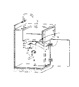
Figure 1 is a schematic of the waste separator and collection system of the
present technology.
Figure 2 is a schematic of the waste separator of the system of Figure 1.
Figure 3A is a longitudinal sectional view of the waste separator of Figure 2
taken along line 3A;
and Figure 3B is a cross sectional view of the waste separator of Figure 2,
taken along line 3B.
Figure 4 is a schematic of the distal end of the transverse pipe.
Figure 5 is a schematic of the bin of the system of Figure 1.
Figure 6 is a side view of the bin in place on the waste separator in the
cabinet.
Figure 7 is a schematic of the electronics of the system.
Figure 8A is a schematic of the microprocessor and switch; Figure 8B is a
schematic of the
microprocessor and a Bluetooth radio; and Figure 8C is a schematic of the
Bluetooth radio in
further communication with an application on a mobile device.
DESCRIPTION
Except as otherwise expressly provided, the following rules of interpretation
apply to this
specification (written description and claims): (a) all words used herein
shall be construed to be
of such gender or number (singular or plural) as the circumstances require;
(b) the singular terms
"a", "an", and "the", as used in the specification and the appended claims
include plural
references unless the context clearly dictates otherwise; (c) the antecedent
term "about" applied
to a recited range or value denotes an approximation within the deviation in
the range or value
known or expected in the art from the measurements method; (d) the words
"herein", "hereby",
6
CA 3011856 2018-07-16
"hereof", "hereto", "hereinbefore", and "hereinafter", and words of similar
import, refer to this
specification in its entirety and not to any particular paragraph, claim or
other subdivision, unless
otherwise specified; (e) descriptive headings are for convenience only and
shall not control or
affect the meaning or construction of any part of the specification; and (f)
"or" and "any" are not
exclusive and "include" and "including" are not limiting. Further, the terms
"comprising,"
"having," "including," and "containing" are to be construed as open ended
terms (i.e., meaning
"including, but not limited to,") unless otherwise noted.
Recitation of ranges of values herein are merely intended to serve as a
shorthand method of
referring individually to each separate value falling within the range, unless
otherwise indicated
herein, and each separate value is incorporated into the specification as if
it were individually
recited herein. Where a specific range of values is provided, it is understood
that each intervening
value, to the tenth of the unit of the lower limit unless the context clearly
dictates otherwise,
between the upper and lower limit of that range and any other stated or
intervening value in that
stated range, is included therein. All smaller sub ranges are also included.
The upper and lower
limits of these smaller ranges are also included therein, subject to any
specifically excluded limit
in the stated range.
Unless defined otherwise, all technical and scientific terms used herein have
the same meaning
as commonly understood by one of ordinary skill in the relevant art. Although
any methods and
materials similar or equivalent to those described herein can also be used,
the acceptable
methods and materials are now described.
Definitions:
Computing device ¨ in the context of the present technology, a computing
device is a cellular
phone, a tablet, a laptop, desktop or purpose-built computing device. It has a
memory and a
processor.
Handheld, mobile device ¨ in the context of the present technology, a
handheld, mobile device
is a cell phone, a tablet or a laptop.
7
CA 3011856 2018-07-16
Dishwasher wastewater ¨ in the context of the present technology, dishwasher
wastewater is a
mixture of liquid waste and organic solids that is pumped out of the
dishwasher and into the
drain.
Sink wastewater ¨ in the context of the present technology, sink wastewater is
a mixture of liquid
waste and organic solids that is released from the sink into the drain.
Filtered wastewater ¨ in the context of the present technology, filtered
wastewater is water that
has passed through the filter in the waste separator and has a significantly
reduced solid organic
waste content.
Detailed Description:
A waste separator and collector system, generally referred to as 10 is shown
in Figure 1. A waste
separator, generally referred to as 12, is placed in-line on the drain pipe
14, between the sink 16
and the trap 18. As shown in Figure 2, it has two inlets for waste, a
dishwasher wastewater inlet
20 and a sink wastewater inlet 22 and two outlets, a solid waste outlet 24 and
a filtered water
outlet 26. Returning to Figure 1, the collector is a closed bin 30.
As shown in Figure 2, a housing, generally referred to as 32, includes an
upper pipe 34, a
transverse pipe 36 and a lower pipe 38. The upper pipe 34 has an upper bore 40
that terminates
in the sink waste inlet 22. The sink wastewater inlet 22 is sized to accept
the upper section of
the sink drain pipe 14 (shown in Figure 1). A flange 42 encircles the upper
pipe 34 at the sink
wastewater inlet 22. The dishwasher wastewater inlet 20 enters the upper bore
40 through the
sidewall 44. The dishwasher wastewater inlet 20 has a male end 46 for mating
with the female
end of the dishwasher drain hose. As shown in Figure 3A, the transverse pipe
36 has a transverse
bore 50 that terminates distally at the solid waste outlet 24 and is connected
proximally to an
electric motor housing 52. The lower pipe 38 has a lower bore 54 that
terminates at a closed
bottom 56. In an alternative embodiment the lower pipe is bowl-shaped and
terminates at the
closed bottom 56. The lower pipe and bowl are collectively referred to as a
vessel. The drain
outlet 26 is normal to the lower pipe 38 and has a drain bore 60 that is of a
smaller diameter than
the lower bore 54. The drain bore 60 is sized to accept a standard 1.5 inch
diameter disposal
drain elbow of the drain pipe 14 (shown in Figure 1). The upper bore 40 and
the lower bore 54
8
CA 3011856 2018-07-16
are vertically aligned to create a flow-through bore, generally referred to as
55. The flow-through
bore 55 allows the filtered water outlet 26 to be gravity fed and reduces
entrapment of the liquid
waste in the organic solids being separated by the separator. As shown in
Figure 3B, the
transverse bore 50 houses an auger 62 that is attached to the motor 58 at the
proximal end 64
of the transverse pipe 36. The auger 62 is 3 inches in diameter with a 3 inch
pitch and is 8 inches
long. The auger 62 is a non-cutting auger. This allows the auger to urge the
food scraps to the
solid waste outlet 24 without creating small particles that could clog the
cylindrical filter 66. The
cylindrical filter 66 is attached at both the proximal end 64 and the distal
end 66 of the transverse
pipe 36 and lies between the auger 62 and the inner surface 68 of the
transverse pipe 36. As
shown in Figures 2, and 3A a magnetic flange 70 encircles the transverse pipe
sidewall 71.
The liquid waste and solid organic waste enter the waste separator 12 through
the dishwasher
wastewater inlet 20 and the sink wastewater inlet 22. When they reach the
transverse pipe 36,
the auger 62 drives the organic solid waste towards the solid waste outlet 24
and the liquid waste
continues to flow under the force of gravity through the filter 66 to the
lower pipe 38 as filtered
wastewater. The efficiency of the process is demonstrated in Example 1.
As shown in Figure 4, the distal end 66 of the transverse pipe 36 has a
normally-closed solenoid
flap valve 72. A gasket 74 sits between the distal end 66 and the flap valve
72 to ensure that
when the flap valve 72 is in the closed position, no water can escape from the
separator 12 and
no odours can escape from the bin 30. A solenoid hook bolt lock set 76 holds
the flap valve 72
in the closed position.
As shown in Figure 5, the bin 30 has a bottom 80, sides 82, a front 84, a back
86 and a top 88. At
least a part of the top 88 is a lid 90. The lid 90 has a hinge 92 which is
either attached to the top
88 or the back 86, preferably the top 88 so the inside of the bin 30 stays as
smooth as possible.
A gasket 94 reduces or eliminates odours escaping from the bin 30. A latch 96
further reduces
or eliminates odours escaping. A handle 98 is located on the front 84. An
aperture 100 in the
back 86 is sized to accept the solid waste outlet 24. A movable seal, which is
preferably a pair of
flaps 102 around the aperture 100 reduces or eliminates air movement between
the bin interior
104 and the ambient.
9
CA 3011856 2018-07-16
As shown in Figure 6, when the bin 30 is in the collecting position, the
distal end 66 of the
transverse pipe 36 is in the bin interior 104, the flaps 102 are pushed aside
and the magnetic
flange 78 abuts the back 86, forming a magnetic seal between the back 86 and
the flange 78.
This magnetic seal further reduces or eliminates odours from escaping and also
reduces or
eliminates residual water from escaping. The bin 30 has slides 120 on the
bottom 80 that run on
rails 122 on the mounted on the base 124 of the cabinet 126.
As shown in Figure 7, a microprocessor 250 is housed in the motor housing 52.
The motor 58,
the normally-closed solenoid valve solenoid 200, the hook latch set solenoid
206, a sensor 240,
a weigh scale 252 and an alarm 254 are under control of the microprocessor 250
and therefore
they are in electrical communication with the microprocessor 250. The
microprocessor 250
directs the motor 58 through different cycles other than the primary one of
auguring the organic
waste into the bin 30, for example running backwards to remove a blockage,
running at different
speeds and stopping. Returning to Figure 6, the sensor 240 is located in the
bin 30 and reports
when the bin 30 is full. It may be, for example, but not limited to an optical
sensor 240, which is
angled downward, in which case a light source would be included 242, or it
might be a pressure
sensor that senses pressure increases caused by the organic waste pressing
against the sensor,
or a mechanical switch. The optical sensor 240 is powered by a battery that is
housed in a battery
housing 256 on the back 86. This results in the microprocessor 250 instructing
the alarm 254 to
sound. The weigh scale 252 reports the weight of the organic waste.
As shown in Figure 8A, in one embodiment, the waste separator and collector
system 10 is wired
to a switch 300. In another embodiment shown in Figure 8B, the microprocessor
250 is hardwired
and a Bluetooth receiver 302 is in electrical communication with the
microprocessor 250. A
Bluetooth transceiver 304 in a mobile device 306, for example, but not
limited to a cellular
phone, a tablet or laptop, is in radio communication with the Bluetooth
receiver 302 and sends
instructions to the microprocessor 250. In another embodiment shown in Figure
8C, there is a
Bluetooth transceiver 308 in electrical communication with the microprocessor
250. The
transceiver 306 sends organic waste weight data to an application 310 on the
mobile device 306
via the Bluetooth transceiver 304. This allows the application 310 to track
the amount of waste
produced over time.
CA 3011856 2018-07-16
Example 1
The waste separator and collector system 10 was run and the following data
were obtained:
- Average food waste extracted: 95%.
- Average free liquids removed: 100%.
- Longest dimension of solids capable of being processed (not including
soft organics e.g. banana
peels, which can be much larger): 3 inches.
- Filter size (minimum food waste size): 5/32 inch (noting that smaller food
particles may be
augured by being entrapped within larger particles).
- Running time: 6 seconds minimum.
- Max power: 200W.
While example embodiments have been described in connection with what is
presently
considered to be an example of a possible most practical and/or suitable
embodiment, it is to be
understood that the descriptions are not to be limited to the disclosed
embodiments, but on the
contrary, is intended to cover various modifications and equivalent
arrangements included within
the spirit and scope of the example embodiment. Those skilled in the art will
recognize or be able
to ascertain using no more than routine experimentation, many equivalents to
the specific
example embodiments specifically described herein. Such equivalents are
intended to be
encompassed in the scope of the claims, if appended hereto or subsequently
filed.
11
CA 3011856 2018-07-16