Note: Descriptions are shown in the official language in which they were submitted.
BIO-METHANOL PRODUCTION
TECHNICAL FIELD
[1] The technical field generally relates to the production of bio-
methanol, and
particularly to processes and systems for producing bio-methanol from
naturally
occurring elements.
BACKGROUND
[2] Liquid biofuel can be produced from a variety of feedstocks and using
various
different processing technologies. Energy and reactant requirements for
conventional
liquid biofuel production techniques can lead to technical and economic
challenges as
well as elevated fossil fuel emissions.
SUMMARY
[3] The techniques described herein relate to a route for the production of
a liquid
biofuel without the engagement of fossil fuels as feedstocks or fossil fuel
sourced
emissions, and more particularly to integrated processes and systems for
producing a
liquid hydrocarbon-based sustainable bio-methanol. The techniques enable
mitigating
fossil fuel derived greenhouse gas emissions from processing and utilization
of
transportation fuels and commercial or industrial alcohols.
[4] Various systems and processes described herein and recited in the
claims reflect
aspects and implementations of the invention.
BRIEF DESCRIPTION OF THE DRAWINGS
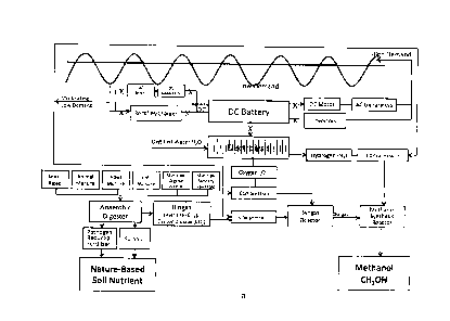
[5] Figure la is a block diagram of an integrated bio-methanol production
process
with greenhouse gas neutrality.
[6] Figure lb is a block diagram of part of a bio-methanol production
process.
[7] Figure 10 is a block diagram of part of a bio-methanol production
process.
[8] Figure id is a block diagram of part of a bio-methanol production
process
showing power sources possibly used during peak and off-peak periods.
1
CA 2980573 2017-09-28
[9] Figure 2 is a block diagram of an integrated bio-methanol production
process
with greenhouse gas neutrality.
[10] Figure 3 is a block diagram of a biomass anaerobic digester.
[11] Figure 4 is a block diagram of a water electrolysis unit operation.
[12] Figure 5 is a block diagram of a partial oxidation unit.
[13] Figure 6 is a block diagram of a synthesis unit and tank farm.
[14] Figure 7 is a block diagram of a generator.
[15] Figure 8 is a block diagram of several integrated units and
illustrating the
electricity source in terms of its supply-demand balance characteristics.
[16] Figure 9 is another block diagram of an integrated bio-methanol
production
process.
[17] Figure 10 is a block diagram of part of a bio-methanol production
process.
[18] Figure ills another block diagram of part of a bio-methanol production
process.
[19] Figure 12 is another block diagram of part of a bio-methanol
production process.
[20] Figure 13 is another block diagram of part of a bio-methanol
production process.
[21] Figure 14 is a graph of throughput/production versus electricity
source for an
example bio-methanol production process.
DETAILED DESCRIPTION
[22] Various techniques are described herein for bio-methanol production.
In some
implementations, systems and processes are provided for the production of bio-
methanol (which may be referred to here as ECOLENEC). The bio-methanol can be
dedicated as a liquid transportation biofuel, as a commercial/industrial
alcohol, and/or as
a liquid biofuel for generating greenhouse gas neutral electricity
particularly during peak
electrical demand periods. The bio-methanol can also be dedicated as a liquid
storage
medium for surplus and low-demand nuclear and/or renewable electricity as well
as a
2
CA 2980573 2017-09-28
novel medium for temporary storage of captured greenhouse gases from
decomposed
biomass for delayed release back to the atmosphere for balancing via
photosynthesis.
[23] One or more batteries can be implemented for powering electrolysis,
where the
battery unit can be charged during off-peak electricity demand and then used
to power
electrolysis during peak electricity demand. The battery-based methodology can
also be
integrated with the periodic use of bio-methanol as fuel for a generator that
generates
electricity for powering electrolysis. The electrolysis unit, which may
include one or more
electrolysis devices, can therefore be configured to receive power from
multiple sources,
notably from an AC source (e.g., grid) during off-peak periods, and from one
or more
batteries and/or one or more generators during peak periods. The power input
from the
different power sources can be modulated based on lower cost or higher
availability of
the electric power, or various other methods based on factors such as
accumulated
inventory (e.g., of bio-methanol), battery charge level, power demand for
electrolysis,
overall greenhouse gas emissions or life cycle analyses, and so on.
[24] Described herein is thus an integrated technology that can activate a
transition
from emitting greenhouse gases, exhausted from fossil fuel combustion and
decomposing biomass, to synthesize a liquid hydrocarbon (bio-methanol), while
storing
variable quantities of intermittently available surplus and low demand (off-
peak)
alternating current (AC) electricity in direct current (DC) storage batteries,
while
facilitating the provision of a steady state of DC to electrolyze water for
the production of
hydrogen and oxygen used to synthesize methanol, engaging only intermittently
idled
electricity generation and waste biomass. A portion of the surplus and low
demand AC
based power stored in DC batteries, while enabling a steady state production
of
hydrogen and oxygen from water, may be converted back to AC to serve variable
periods of high demand (peak) electricity.
[25] In addition, DC storage of surplus system-based AC enables DC battery
banks to
be incrementally expanded to serve this dual purpose in the transitioning of
electricity
supply to renewables, together with harmonizing system electricity supply and
demand.
[26] Figure id schematically illustrates an example system in which
different power
sources are used for electrolysis at peak and off-peak periods. Figures la and
lb
illustrate example systems in which a DC battery is used to power
electrolysis.
3
CA 2980573 2017-09-28
[27] In some implementations, a portion of grid-sourced modulating off-peak
Alternating Current (AC) electricity is converted to Direct Current (DC),
using AC-DC
convertor (e.g., rectifiers and/or AC motor-driven DC generators), in variable
amounts
during intermittent periods of reduced electricity system demand, to charge
and/or
recharge expandable banks of DC batteries. In addition, a portion of the AC
electricity is
stored as DC, to operate water electrolysis equipment to produce gaseous
hydrogen
(H2) and gaseous oxygen (02), simultaneously or independently, while
operationally
using a portion of the DC supply to operate DC-AC convertors (e.g., invertors
and/or DC
motor-driven AC generators), to produce system-based electricity during
modulating
periods of high electricity system demand.
[28] The integrated process can facilitate introduction of a novel
technology to
incrementally transition the genesis of synthesizing a climate change benign
hydrocarbon in the form of bio-methanol, to harmoniously replace petroleum-
based
fuels. The process can leverage multiple power sources and thus provide
reliable and
feasible operations for bio-methanol production, while enabling flexible use
of different
power sources in different proportions over time.
[29] The adverse consequences of climate change are motivating the
automotive
industry to transition the use of petroleum to electricity, which creates the
desire for
storing intermittently available periods of surplus low-demand electricity and
releasing
stored energy to provide intermittent periods of high demand electricity.
There may be
many ways to store surplus electricity during low demand and return stored
electricity
during high demand including:
- pumping water uphill during low demand and operating hydro electric
turbine
generators with falling water during high demand;
- compressing air during surplus and low demand periods and releasing
the
compressed air to operate air turbine-driven generators during high demand
periods;
- electrolyzing water to produce hydrogen and oxygen gases during low
electricity
demand and engaging fuel cells and/or combustion turbine generators to
produce electricity during high demand;
4
CA 2980573 2017-09-28
- torquing mechanical energy during low electricity demand and
relieving torqued
energy to mechanically rotate electricity generators during high demand;
- charging Direct Current (DC) batteries during low demand and
converting DC
back to Alternating Current (AC), returning stored electron energy to the
system
during high demand.
[30] In addition, incorporating water electrolysis while charging batteries
and
compressing gases for interim storage during low electricity demand is
reflected on
Figure lb.
[31] In some implementations, there can be more or less a steady state
drawdown on
the storage batteries commensurate with the water electrolysis steady state
demand. In
some implementations, there can be a variable and intermittent drawdown when
DC
energy is required to produce AC back into the system during high demand,
although
this conversion from DC back into AC is optional. The DC storage can be
variable in
accordance with battery energy drawdown and the stored DC can serve as stand-
by
power for a methanol synthesis process, particularly an electrolysis step,
although
alternatively for other units for production of a biofuel in general.
[32] The adverse consequences of climate change are also motivating the
agricultural
industry and urban communities to utilize urban organic wastes (e.g., from
landfills),
together with sanitary sewerage and all forms of domestic animal, fowl and
aquaculture
manures to be collectively digested without access to air, to produce, contain
and utilize
massive volumes of biogas which would otherwise blend with fossil fuel
emissions into
the atmosphere. Presently, biomass, which decomposes into biogas, consisting
primarily
of methane (CH4) and carbon dioxide (CO2) is burned in combustion turbine
generators
to generate electricity and/or to supplement natural gas distribution.
However, biogas is
a lower quality combustion fuel since the CO2 content in biogas acts as an
extinguisher
reducing the heat rate and is passed into the atmosphere as greenhouse gas
emissions.
Anaerobic digestion of rural and urban biomass to produce, contain and utilize
naturally
occurring methane (CH4) and carbon dioxide (CO2) when used to integrate with
sustainable hydrogen (H2) and oxygen (02) in a steady state or batch process
is
reflected on Figure lc.
CA 2980573 2017-09-28
[33] The incorporation of batteries for powering electrolysis provides a
number of
advantages. For example, by incorporating DC batteries for storing variable
amounts of
intermittently available surplus and low demand grid-sourced AC, expandable
battery
banks may be used to power water electrolysis for the steady state production
of
hydrogen and oxygen which can reduce or eliminate the need for certain
electrolysis
plant redundancies. Reliable electrolysis operation in addition to flexible
power sourcing
are facilitated. By enabling renewable/sustainable biomass to generate a
regular supply
of biogas, together with a steady state supply of hydrogen and oxygen from
electrolysis,
the processing of a sustainable liquid bio-hydrocarbon (e.g., bio-methanol)
can be
advantageously synthesized as a sustainable substitute for petroleum products.
[34] Referring to Figures 2 to 14, the overall system and certain process
variants will
be described that include a battery and an optional bio-methanol fueled
generator. It
should be noted that various figures that illustrate the battery-based option,
for instance
Figure 2 and others, should be understood as being schematic illustrations
that do not
necessarily show all of the equipment or components that could be used in
implementations of the system. For example, such figures may not explicitly
illustrate
AC-DC or DC-AC converters or other components shown in Figure la for instance,
but
such components may be included where required as part of any of the example
systems illustrated and/or described herein.
[35] Referring to Figure 2, the system can include integrated units for bio-
methanol
production and can include an anaerobic digester unit, a partial oxidation
unit, a
synthesis unit, a storage facility, a water electrolysis unit, a battery
including associated
equipment, and an optional modulating electricity generator.
[36] Referring to Figures 2 and 3, in some implementations the anaerobic
digester is
configured to receive one or more biomass feedstocks, such as manures, organic
wastes, sanitary sewerage, cellulose (e.g., pulverized cellulose), algae
and/or extracts or
fractions thereof, and so on. The biomass feedstocks can be sourced locally
and can
include a combination of different hydrocarbon and carbohydrate sources, and
also
including algae and/or extracts thereof for example. The digester can be
operated to
produce biogas as well as sulphur and fertilizer by-product streams. The
sulphur can be
harvested incrementally and the composted fertilizer can also be recovered
periodically,
as by-products. The fertilizer can be recovered as a coliform-free material
and can be
6
CA 2980573 2017-09-28
processed for sale and/or used in a dedicated biomass production facility
(e.g., a
greenhouse) that may also use CO2 that is produced by the process. Both the
fertilizer
and the CO2 generated by the process can be stored and then supplied as needed
to a
biomass production facility (e.g., during certain biomass production cycles).
In some
cases, the biomass that is produced can then be harvested as part of the
feedstock
supplied to the anaerobic digester. A biogas storage unit can be provided to
receive and
store biogas from the digester. A biogas compressor can be provided to operate
the
digester at or near steady state in order to prevent exhausting and/or flaring
of biogas
during surplus biogas production periods and other times of the processing.
The biogas
storage can be monitored and controlled to retrieve and supply controlled
amounts of the
biogas to the partial oxidation unit, for example. Such control can also
incorporate input
from other process units. The biogas production can be monitored and
controlled to
obtain a composition within a pre-determined range, particularly with respect
to the
stoichiometric balance of methane and carbon dioxide, for example to maximize
production and utilization.
[37] In some implementations, biogas can be burned directly in the
generator, for
example in periods of biogas overproduction and/or during outages of partial
oxidation
and/or synthesis reactors to avoid emissions. The generator unit can include
combustion
generator devices that are adapted to receive biogas and/or bio-methanol
streams as
fuel (alternately and/or simultaneously), and/or the generator unit can
include multiple
generator devices each dedicated to a given fuel (e.g., a biogas-receiving
generator, a
bio-methanol-receiving generator, etc.).
[38] Referring to Figures 2 and 4, in some implementations the water
electrolysis unit
is configured to receive distilled water and electricity from non-fossil fuel
sources. The
water can be obtained from a water distillation unit or another type of water
purification
unit that may be located on site or proximate to the water electrolysis unit,
for example.
Energy required for water distillation can be obtained in whole or in part
from renewable
sources, such as biomass or bio-methanol combustion. The water electrolysis
unit can
be fully variable, fully interruptible and outfitted with compressors and
storage vessels to
ensure a constant regulated supply of output (oxygen and hydrogen) are
available
during interruption and/or high electricity demand periods. By-product heat
from the
water electrolysis unit can be captured and delivered to the digester and/or
to pre-
treatment units for pre-treating the biomass prior to entering the digester.
The by-product
7
CA 2980573 2017-09-28
heat recovery can facilitate temperature control of the digester for
optimizing microbial
production when appropriate. The by-product heat can be supplied to cooling
fans or
towers when the heat is not required elsewhere in the process. In addition,
the water
electrolysis unit can include deuterium harvesting capability, for recovering
deuterium
(heavy water) for use as a heat transfer medium and/or in medical
applications. The
water electrolysis unit can thus be configured and operated to promote
production of
deuterium-rich liquid. For example, the water electrolysis unit can include a
cascade of
electrolysis chambers for concentrating the deuterium in each subsequent
chamber until
pure deuterium is produced, or there may be a separate deuterium
harvester/separator
that is coupled to the water electrolysis unit to receive deuterium-enriched
liquid that can
be further separated into a substantially pure deuterium via chemical exchange
and/or
distillation methods. The electrolysis-derived heavy water can be used in a
nuclear
reactor heat transfer system (e.g., part of a CANDUTM facility).
[39] Referring to Figures 2 and 5, in some implementations the partial
oxidation unit is
fluidly connected with the biogas storage facility and/or the digester, to
receive biogas to
be burned using compressed oxygen sourced from the water electrolysis unit to
produce
syngas comprising or substantially consisting of hydrogen and carbon monoxide.
[40] Referring to Figures 2 and 6, in some implementations the syngas
together with
compressed hydrogen from water electrolysis are supplied to a synthesis unit
configured
to produce non fossil fuel-based bio-methanol, which may be referred to herein
as
ECOLENED.
[41] Still referring to Figures 2, 6 and 7, the bio-methanol can be
supplied to a storage
facility, e.g., tank farm, which can be monitored and controlled in various
ways that will
be described herein. In some implementations, the bio-methanol storage
facility can be
configured for distribution as well as periodic supply to a generator for
electricity
generation. In some implementations, the bio-methanol storage facility is
configured with
sufficient tank storage inventory or capacity to enable periodic electricity
generation, for
example during critical peak demand. The tank storage capacity can therefore
be co-
ordinated with electrolysis electricity demand and peak non fossil fuelled
electricity
demand. The storage facility can also include piping, monitoring
instrumentation, pumps
and control units to manage the storage and the supply of the bio-methanol.
8
CA 2980573 2017-09-28
[42] In some implementations, the capacity to intermittently utilize
surplus and/or low
demand electricity in variable amounts to produce non fossil-sourced
hydrocarbons with
the capacity to intermittently generate critical and high demand electricity
in variable
amounts can facilitate the increasing need to balance electricity supply with
electricity
demand. The capacity to produce bio-methanol during low electricity demand and
use
the bio-methanol and/or battery power to provide electricity during high
electricity
demand can help reduce demand charges and improve the quality of electricity.
In some
scenarios, time-of-day pricing by electricity system operators can be used to
determine
the value for using surplus electricity capacity for purchasing low demand
electricity and
a charge for demand. The capacity to generate electricity using bio-methanol
ECOLENE and/or biogas can be determined by the steady state capacity of the
biogas
using ECOLENE as a back-up biofuel. For example, a 20,000 US gal/day
"regional"
bio-methanol plant may use 75,000 m3 biogas/day, which is generally reflected
in Figure
8.
[43] Time-of-use pricing of electricity can vary depending on various
factors and
locations. For example, in some jurisdictions, off-peak electricity rates can
apply from
approximately 8:00PM-7:00AM and can have a cost that is about 65-75% of the
mid-
peak rate and about 30-55% of the on-peak rate.
[44] In some implementations, the capacities of the different units can be
coordinated
with factors based on electricity demand cycles, estimated fuel market, and
the like. In
some scenarios, the digester is sized and operated to produce between 25,000
m3/day
and 200,000 m3/day biogas, or between 50,000 m3/day and 100,000 m3/day biogas;
the
bio-methanol synthesis unit is sized and operated to produce between 5,000
gal/day and
100,000 gal/day of bio-methanol, or between 15,000 gal/day and 25,000 gal/day;
and
the bio-methanol storage facility has a capacity of between 15,000 gallons and
100,000
gallons, or between 40,000 gallons and 80,000 gallons of the biofuel. Subject
to biomass
availability, much larger bio-methanol plants can be implemented in the
proximity of
large nuclear and/or renewable electricity generating sites.
[45] Referring to Figure 7, a generator can be provided to receive bio-
methanol from
the storage facility and provide electricity to the water electrolysis unit.
The generator
may be specially designed and dedicated for the combustion of bio-methanol to
produce
electricity without emitting fossil fuel sourced greenhouse gases. The
generator can be
9
CA 2980573 2017-09-28
configured to receive different fuels, which may be liquid non fossil-sourced
fuels only or
a combination of liquid non fossil-sourced fuels including biogas. The
combustion of the
bio-methanol and/or biogas would be substantially free of fossil sourced
greenhouse gas
emissions that would be associated with the combustion of fossil fuels, for
example. By-
product heat from the generator can also be used in the process, e.g., for
optimizing the
microbial production in the digester.
[46] An integration assembly can be provided to integrate different units
of the
system. For example, the integration assembly can include the generator, inlet
bio-
methanol fuel piping, electrical supply lines for supplying bio-methanol
generated
electricity to the water electrolysis unit, a control unit coupled to the
piping and/or valves
for controlling the periodic operation of the generator, which may be done
according to
input variables that include electricity demand levels to determine the timing
of peak
demand, as well as various detection and monitoring devices such as
temperature
sensors, pressure sensors and/or flow rate meters and/or actuators. The
integration
assembly may include an automation apparatus, such as a computer, configured
to
control the integration automatically in response to the input variables to
ensure .
pressure/temperature and processing duration for the conversion process (e.g.,
space,
gas, velocity). The integration assembly can also be connected to the battery
and its
associated equipment.
[47] Various techniques described herein can be used in the context of a
carbon
capture, carbon storage, carbon trade, carbon credit, and carbon tax systems.
[48] Production of ECOLENE can enable a liquid hydrocarbon to be
commercially
synthesized by controlled digestion of waste biomass as feedstock to capture
and utilize
methane and carbon dioxide to produce a biofuel rather than enter the
atmosphere
directly as greenhouse gases. By utilizing only renewable- and/or nuclear-
sourced
electricity, to decompose water to produce the essential elements of hydrogen
and
oxygen, unlike other methanol synthesis processes which use fossil fuel-
sourced input
streams, ECOLENE production enables its emissions of carbon dioxide to remain
more
in atmospheric balance through photosynthesis.
[49] In some implementations, the system can be a regional hub that is
located to
serve a remote solar farm, a remote hydraulic generation facility, a remote
wind farm
CA 2980573 2017-09-28
and/or an ocean energy facility where conventional grids or related
infrastructure are
inadequate or do not exist. Bio-methanol can thus be a particularly
advantageous source
of electricity storage and/or a liquid carrier/transporter of electron energy.
Batteries can
also be advantageous in terms of accumulating and storing energy for stable
operation
of the bio-methanol production process.
[50] In some implementations, the bio-methanol can also be used as a liquid
fuel for
various conventional and/or hybrid transportation power trains, as well as
other methods.
Thus, using biomass, water and variable volumes of renewable and/or nuclear
sourced
electricity during low electricity system demand, as described herein, can
enable bio-
methanol to be used to power internal combustion engines for conventional
power trains,
on-board generators for hybrid and/or all electric power trains, carry
hydrogen for fuel
cell powered electric drives and/or generate electricity during high
electricity demand,
qualifying such bio-methanol to be a liquid electricity storage medium
"battery" (N.B., to
be distingu9shed from the electrical battery disclosed herein). Bio-methanol
production,
storage inventory and distribution can be managed to facilitate a plurality of
end-uses
that can be coordinated with advantageous time periods (e.g., electricity
demand
cycles), locations (e.g., regional, infrastructure-deficient, etc.), as well
as various
cost/economic factors. In some implementations, the bio-methanol can also be
used to
charge one or more of the batteries, for example during peak demand periods
and/or
when bio-methanol inventory is high or near capacity of the tank farm.
[51] Referring to Figure 9, the overall bio-methanol fuel production
process is
illustrated where a control unit is coupled to both the electrical output of
the generator
(G), the battery (BA), and an electrical line from an external electricity
source (e), which
may include electricity from an electricity grid dominated with renewable
sources to
ensure the electricity flow is carbon neutral. The control unit can be
configured to receive
information regarding the bio-methanol production process as well as the
external
electricity/power source(s), including cost information for external
electricity as well as
for inputs (e.g., biomass feedstocks) and outputs (e.g., bio-methanol) of the
production
system. The control unit can be configured to balance the electricity sources
(i.e.,
internal and external) to minimize cost or to reduce cost while prioritizing
more
sustainable electricity sources. The control unit can also be configured to
use a certain
electricity source in the event of an outage or maintenance of one of the
other sources
(e.g., batteries can be prioritized when one or more generator is off-line).
11
CA 2980573 2017-09-28
[52] Referring to Figure 10, a water electrolysis unit (WE) can receive
electricity from
external sources (e), internal generator sources (Gi to Gn) and battery
sources (BA, to
BAn). In some scenarios, it may be advantageous to provide multiple generators
(G, to
Gn) and/or multiple batteries (BA) which can be operated individually or
together
depending on the electricity demand from the water electrolysis unit (WE). For
example,
during high throughput/production periods and peak demand, multiple or all of
the
generators and/or batteries can be operated to provide electricity; while
during lower
throughput/production periods and/or off-peak, only some or none of the
generators
and/or batteries can be operated to provide electricity. Multiple smaller
generators and/or
batteries, all of which can be coupled to a central control unit, can thus be
used in a
modular fashion to tailor the electricity generation in a flexible manner that
can adapt to
both external electricity cost and availability and the production mode (e.g.,
high
production, start-up, turndown, upset, etc.) of the bio-methanol production
process.
[53] Referring to Figure 11, the water electrolysis unit (WE) can be
coupled to multiple
external electricity sources (e, to e3), each of which can originate from a
different
electricity generation method. For example, a first external electricity
source (el) may be
wind-generated, a second external electricity source (e2) may be hydro-
generated, a
third external electricity source (e3) may be nuclear-generated, while other
external
electricity sources may come from various other renewable sources, some of
which have
been mentioned above. By coupling the bio-methanol production process to
multiple
external electricity sources, access to renewable electricity can be more
robust
particularly when some of the output from the renewable sources is
inconsistent or
difficult to predict in terms of availability and/or cost. For example,
certain renewable
energy sources are weather dependent (e.g., wind) and thus by providing
multiple
external sources, the process can operate more efficiently. In addition, the
control unit
can be configured to select and balance the electricity sources that are used
for the
water electrolysis unit based on fluctuations in each external electricity
source.
[54] Referring to Figure 12, multiple water electrolysis units can be
provided and in
some cases can employ one or more common external electricity source (e). The
multiple water electrolysis units can be part of the same overall bio-methanol
production
process or they can be part of two distinct and potentially remote processes,
e.g.,
provided in two different regional locations. Each water electrolysis unit
(WE, and WE2)
can be coupled to its own generator (G, and G2 respectively) and/or battery
(BA, and
12
CA 2980573 2017-09-28
BA2 respectively), where the generators can in turn be coupled to two
different storage
facilities (Si and S2 respectively) or to a single central storage facility.
This general
configuration can be particularly advantageous for implementing multiple bio-
methanol
production plants in a plurality of remote locations that are nevertheless
serviced by a
common electrical grid and/or by common external electrical sources. In
addition, a bank
of generators can include a primary generator as well as backup generators,
which can
come online quickly and periodically to facilitate avoiding spikes in peak
demand. There
may also be a bank of batteries with a primary battery as well as backup
batteries, which
can come online quickly and periodically to facilitate avoiding spikes in peak
demand.
There may alternatively be a primary battery or generator, and at least one
backup of the
other type of electricity source (generator or battery). Multiple generators
and/or
batteries can thus be particularly advantageous when there are sudden, large
and/or
unpredictable spikes in peak demand, by facilitating rapid adjustment.
[55] In some implementations, the primary generator (G1) or battery (BA1)
can be
designed and provided to be able to respond to normal electricity requirements
during
peak demand periods and typical operation of the bio-methanol production
plant, while a
secondary or backup generator (G2) or battery (BA2) is a smaller unit designed
for more
occasional operation during sudden peaks, emergency demand periods, and/or
when
bio-methanol price is lower than external electricity cost. In some
implementations, one
or more generators can be designed to utilize the bio-methanol as the
dedicated fuel,
while one or more additional generators are provided for use with other fuel
sources
(e.g., biogas) or as fuel-neutral units that can receive methanol, biogas
and/or other fuel
sources for electricity generation.
[56] Referring to Figure 13, the bio-methanol production process can
include multiple
water electrolysis units (WE, and WE2) that are part of the same production
plant and
are operated in accordance with electricity sourcing strategy and the bio-
methanol
production mode. For example, during low throughput/production (e.g. during
start-up or
turndown modes, maintenance, or feedstock modification) a single water
electrolysis unit
may be used and it may be supplied with electricity based on the above-
described
methods by using off-peak electricity from the external source (e), and bio-
methanol
generated electricity or battery power during peak periods. As the production
process
ramps up, the second water electrolysis unit can come online and can be
supplied by
both external and internal sources of electricity (generator and/or battery),
as described
13
CA 2980573 2017-09-28
above. A bank of multiple water electrolysis units can provide additional
flexibility for bio-
methanol production processes, particularly when the plants have variable
throughputs
and production.
[57] In addition, the production rate of the process can also be controlled
based on
electricity availability and cost. For example, during peak demand, the
production rate
can be decreased in conjunction with using bio-methanol to generate
electricity for
operating the water electrolysis unit(s) or using battery power. This can be
particularly
advantageous in the case that the bio-methanol market price is high and/or
when the
biomass feedstock cost is high, thereby reducing the consumption of bio-
methanol for
generating electricity while keeping the process operational during peak
demand
periods. Alternatively, when bio-methanol price and feedstock cost are low,
the
production rate can be maintained at substantially the same levels as during
off-peak
operations.
[58] Turning to Figure 14, an example of modulating throughput and
production rate
of the process based on the different electricity inputs (e), (G) and (b) is
illustrated. One
can also integrate the cost of biomass feedstocks, the price of the bio-
methanol, and
capital/operating costs of the battery units, into the control strategy which
can be
implemented in automated fashion by a control unit that is coupled to the
various units of
the process.
[59] Advantageously, off-peak external electricity consists of electricity
from non-fossil
fuel sources. Various examples of non-fossil fuel sources of electricity are
provided
further above. Further examples are (i) when nuclear reactors are modulated or
when
primary nuclear sourced steam is being quenched, (ii) when wind energy
generation is
being strategically curtailed, (iii) when hydro-energy is being spilled as
part of a supply
management strategy. A number of variable electricity sources can be used.
[60] In addition, since water electrolysis units can incrementally and
quickly modulate
demand, utilizing water electrolysis units in the context of the techniques
described
herein facilitates critical load manipulation. Electrolysis interruption is
ideally avoided and
thus leveraging the battery stored energy and/or the bio-methanol for
providing electricity
dedicated for maintaining electrolysis operation facilitates efficient
operation of the
process.
14
CA 2980573 2017-09-28
[61] In some implementations, the generator (G) is a dedicated bio-methanol
combustion unit that is designed and operated for use with 100% methanol as
fuel.
Alternatively, the generator can be used for various different fuel types,
including
methanol. In some implementations, the combustion gas generated by the
generator(s)
is recuperated and reused either within the bio-methanol production process or
in other
processes. For instance, in some scenarios, the CO2 in the combustion gas can
be
separated and reused in the process, in another system (e.g., greenhouses for
photosynthesis and production of biomass including cultured algae as an
example),
and/or in a capture/sequestration system. The CO2 in the combustion gas can be
prepared and supplied directly to a CO2-utilization facility or can be
captured from the
combustion gas and stored as substantially pure CO2 for use. Heat generated by
the
generator can also be used in a biomass generation facility, such as a
greenhouse, or
other external or internal units. In some scenarios, at least one of the
generators can be
portable to facilitate relocation as need be, e.g., between two remote process
locations.
[62] In some implementations, the one or more batteries can be charged
using one or
more sources. For example, the battery can be charged using off-peak
electricity from
the grid, other energy sources as mentioned above, combustion of bio-methanol,
and/or
combustion of other fuels that are non-fossil fuels (e.g. biomass based). The
battery
charging approach can be based on various strategies, and can prioritize
various energy
sources based on availability, sustainability, cost, availability of other
energy sources at
different times (e.g., peak versus off-peak), electrolysis electricity demand,
and so on.
[63] Units and components of the systems described herein can also be used
and
configured in various ways. For example, certain unit operations can be
provided as a
serial or parallel bank of units. Another example is that processes described
herein can
be adapted for production of liquid biofuel other than bio-methanol by
periodically using
liquid biofuel as a source of electricity for one or more units during peak
demand
periods, particularly when such electricity is supplied to a water
electrolysis unit or
another unit having similar electricity requirements. In addition, multiple
generators
and/or batteries can be provided in parallel, the generators being able to
process
different amounts of bio-methanol to produce electricity for the water
electrolysis unit
depending on the electricity demand, the electrolysis electricity demand
and/or the
inventory of bio-methanol.
CA 2980573 2017-09-28