
Category: Electricity
Specification: PS-E-15
Document(s): Specifications for Approval of Type of Electricity Meters, Instrument Transformers and Auxiliary Devices, LMB-EG-07(1986)
Distribution Date: 2007-05-03
Effective Date: 2007-05-03
Supersedes:
Table of contents
- 1.0 Scope
- 2.0 Authority
- 3.0 References
- 4.0 Terminology
- 5.0 General requirements
- 6.0 Ratings
- 7.0 Electrical requirements
- 8.0 Marking requirements
- 9.0 Metrological requirements
- 10.0 Sealing requirements
- 11.0 Additional information
1.0 Scope
This provisional specification applies to electronic voltage transformers which are intended to be used in revenue metering.
2.0 Authority
These provisional specifications are issued under the authority of section 12 of the Electricity and Gas Inspection Regulations.
3.0 References
3.1 Specifications for Approval of Type of Electricity Meters, Instrument Transformers and Auxiliary Devices, LMB-EG-07(1986).
3.2 Application of New Specifications and Approval of Trade Measurement Devices that Incorporate Technologies not Covered by the Existing Specifications, GEN-06
3.3 CAN-CSA C60044-2, Instrument Transformers Part 2: Voltage Transformers
3.4 CAN-CSA C60044-7, Instrument Transformers Part 7: Electronic Voltage Transformers
4.0 Terminology
- Electronic Instrument Transformer (EIT)
-
An arrangement consisting of one or more current or voltage sensors which may be connected to transmitting systems and secondary converters, all intended to reproduce in it's secondary circuit, in a definite and known proportion the current or voltage of it's primary circuit with the phase relations substantially preserved.
- Electronic Voltage Transformer (EVT)
-
An EIT in which the secondary voltage in normal conditions of use is substantially proportional to the primary voltage and differs in phase from it by a known angle for an appropriate direction of the connections.
Note: The terms "measuring voltage transformer" and "metering voltage transformer" are equivalent
5.0 General requirements
Electronic voltage transformers shall comply with all applicable requirements 3-2.1, 3-2.4, 3-2.6, 3-3.2.2, 3-3.6, 3-5.3 of LMB-EG-07 in addition to the other requirements specified in this document.
6.0 Ratings
6.1 Rated primary voltage
Ratings shall be those established in section 14-3.4 of LMB-EG-07.
6.2 Standard burden
The standard metering burdens for EVT shall be in accordance with Table 1.
7.0 Electrical requirements
7.1 Dielectric tests
The EVT shall meet the insulation requirements established in section 14-3.2.1 of LMB-EG-07.
7.2 Temperature rise
The EVT shall meet the temperature requirements established in section 14-3.2.2 of LMB-EG-07.
8.0 Marking requirements
8.1 Terminals
The EVT terminals shall be identified as established in section 14-3.3.1 of LMB-EG-07.
8.2 Relative polarities
All terminals of the EVT marked H1, X1, Y1 shall have the same polarity at the same instant.
8.3 Nameplate
The EVT nameplates shall include all applicable information as established in section 14-3.3.2 of LMB-EG-07 and positioned as stated in section 14-3.3.2.1 of LMB-EG-07.
9.0 Metrological requirements
9.1 Basic accuracy
Accuracy classes for the EVT are based on the requirement that the transformer correction factor (TCF) shall be within specified limits for the following conditions:
- 90% to 110% of accuracy-rated voltage;
- voltage corresponding to the continuous rating factor as per Table 10B of CAN/CSA C60044-2 standard;
- power factor (lagging) of metered power load from 0.6 to 1.0; and
- burden of a specified standard value (meaning from 0 to specified burden) for indicated service conditions.
The relationships between the limits of the ratio correction factors and the phase angle for the limiting values of the TCFs specified in Table 2 are shown in the parallelogram in Figure 1.
| Accuracy Classes | Limits of Transformer Correction Factor for 90% to 110% Accuracy-Rating Voltage Footnote 1 | Limits of Power Factor (Lag) of Metered Power Load | |
|---|---|---|---|
| Minimum | Maximum | ||
| 0.15 | 0.9985 | 1.0015 | 0.6-1.0 |
| 0.3 | 0.997 | 1.003 | 0.6-1.0 |
| 0.6 | 0.994 | 1.006 | 0.6-1.0 |
Footnotes
- Footnote 1
-
These limits also apply at the maximum continuous voltage rating factor.
- Only the EVTs of accuracy class 0.15, 0.3 and 0.6 may be approved for revenue metering.
- The accuracy required for 100% rated voltages is also applicable to the rated voltage factor of the EVTs.
Figure 1–Limits for measuring voltage transformer
Limits of 0.15 accuracy class
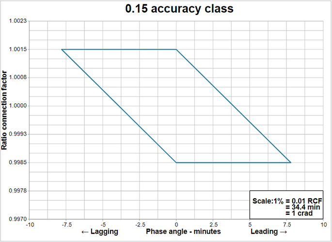
Description of limits of 0.15 accuracy class figure
The relationships between the limits of the ratio correction factors and the phase angle for the limiting values of the transformer correction factors (TCFs) specified in Table 2 are provided by parallelograms that are plotted on graphs in which a phase angle correction factor in minutes appears on the x-axis and a ratio correction factor appears on the y-axis. The parallelograms defining the limiting values of the TCFs for voltage transformers are bound by vertices. For a 0.15 accuracy class the limiting values are (0, 1.0015), (7.8, 1.0015), (0, 0.9985) and (7.8, 0.9985).
Limits of 0.3 accuracy class
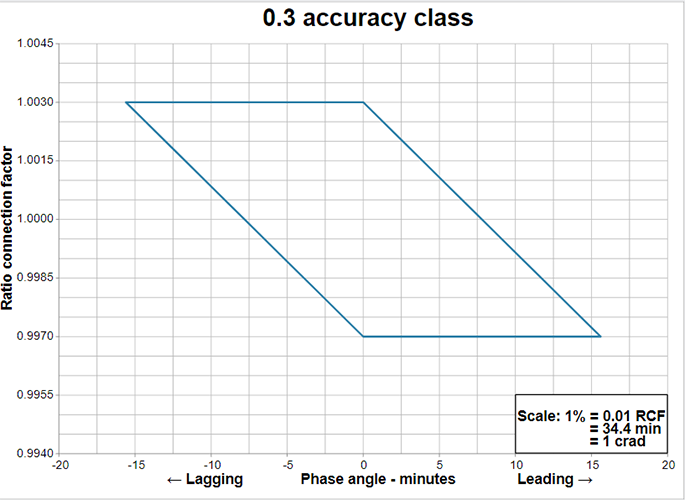
Description of limits of 0.3 accuracy class figure
The relationships between the limits of the ratio correction factors and the phase angle for the limiting values of the transformer correction factors (TCFs) specified in Table 2 are provided by parallelograms that are plotted on graphs in which a phase angle correction factor in minutes appears on the x-axis and a ratio correction factor appears on the y-axis. The parallelograms defining the limiting values of the TCFs for voltage transformers are bound by vertices. For a 0.3 accuracy class the limiting values are (0, 1.003), (15.6, 1.003), (0, 0.997) and (15.6, 0.997).
Limits of 0.6 accuracy class
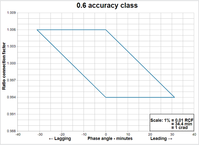
Description of limits of 0.6 accuracy class figure
The relationships between the limits of the ratio correction factors and the phase angle for the limiting values of the transformer correction factors (TCFs) specified in Table 2 are provided by parallelograms that are plotted on graphs in which a phase angle correction factor in minutes appears on the x-axis and a ratio correction factor appears on the y-axis. The parallelograms defining the limiting values of the TCFs for voltage transformers are bound by vertices. For a 0.6 accuracy class the limiting values are (0, 1.006), (31.2, 1.006), (0, 0.994) and (31.2, 0.994).
9.2 Accuracy versus temperature
The EVT shall meet its basic accuracy requirement 9.1 when tested according to requirement 8.3.2 of CAN/CSA C60044-7 (IEC 60044-7).
9.3 Accuracy versus frequency
The EVT shall meet its basic accuracy requirement 9.1 when tested according to requirement 8.3.3 of CAN/CSA C60044-7 (IEC 60044-7).
9.4 Accuracy versus auxiliary voltage variation
The EVT shall meet its basic accuracy requirement in 9.1 when its auxiliary voltage is varied ±10% from the nominal AC auxiliary voltage; and when varied ±20% from the nominal DC auxiliary voltage.
10.0 Sealing requirements
10.1 Programming security
The basic operating constant and the algorithm used in processing the measured quantities shall be stored within the EVT in such manner that they cannot be altered without breaking the device's physical seal (clause 3-2.6 of LMB-EG-07). All operating, metering constants and algorithms shall not be modified or altered by any external device, communication signal, power outage or any other means which does not require breaking the device's physical seal.
11.0 Additional information
For additional information regarding this provisional specification, please contact the Senior Program Officer responsible for electricity measurement.
Alan E. Johnston
President
Measurement Canada